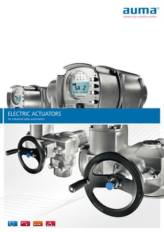
Electric Actuators for Industrial Valve Automation
•
4 likes•4,330 views

This brochure intends to describe functions and possible applications for electric actuators, actuator controls and gearboxes. The document offers an introduction into the topic, an overview on products and founded explanations regarding design and function of electric AUMA actuators. On the rear pages of this brochure, you will find a chapter with detailed technical data for swift product selection. For device selection, further information can be obtained from our separate product specific data sheets.

Recommended
More Related Content
What's hot
What's hot (20)
Similar to Electric Actuators for Industrial Valve Automation
Similar to Electric Actuators for Industrial Valve Automation (20)
More from Classic Controls, Inc.
More from Classic Controls, Inc. (20)
Recently uploaded
Recently uploaded (20)
Electric Actuators for Industrial Valve Automation
- 1. ELECTRIC ACTUATORS for industrial valve automation
- 2. 2 ABOUT THIS BROCHURE This brochure intends to describe functions and possible applications for electric actuators, actuator controls and gearboxes. The document offers an introduction into the topic, an overview on products and founded explanations regarding design and function of electric AUMA actuators. On the rear pages of this brochure, you will find a chapter with detailed technical data for swift product selection. For device selection, further information can be obtained from our separate specific data sheets. It will be our pleasure to assist you and provide any further details that might be needed. The latest information on AUMA products can be found on the Internet at www.auma. com. All documents, including dimensional drawings, wiring diagrams, technical and electrical data sheets, as well as inspection certificates are available on the Internet in digital form.
- 3. 2016.03.11 3 Multi-turn actuators: Gate valves Part-turn actuators: Butterfly valves, plug and ball valves Linear actuators: Globe valves Lever actuators: Dampers Who are AUMA? About this brochure 2 AUMA - The specialist for electric actuators 4 Basics Applications 6 What is an electric actuator? 8 SA multi-turn actuators and SQ part-turn actuators 10 Automation solutions for any valve type 12 Service conditions 14 Basic actuator functions 18 Controls concepts 20 Operation and clarity Integration within the DCS - AM and AC actuator controls 22 Clearly structured operation 24 Reliability, service life, maintenance - with test engineering features 26 AUMA CDT for AC controls - easy commissioning 28 AUMA CDT for AC controls - diagnostics dialogue 30 Communication Communication - tailor-made interfaces 32 Communication - fieldbus 34 Communication - HART 38 SIMA - the fieldbus system solution 40 Alternative communication channels - Wireless and fibre optic cables 42 Design Uniform design for SA and SQ 44 Electromechanical control unit 50 Electronic control unit 51 Interfaces Valve attachment 52 Electrical connection 54 Solutions for all combinations Multi-turn actuator - part-turn gearbox combinations - for large torques 56 Special circumstances - adapting to any mounting position 58 Safety Protection for valve, protection during operation 62 Functional safety - SIL 64 Technical data SA multi-turn actuators and SQ part-turn actuators 66 AM and AC actuator controls 72 SA/GS part-turn actuators 75 SA/GK multi-turn actuators 79 SA/GST multi-turn actuators 80 SA/GHT multi-turn actuators 81 SQ part-turn actuators with base and lever anD SA/GF 82 SA/LE linear actuators 83 Certificates 84 Index 86
- 4. 44 Armaturen- Und MaschinenAntriebe - AUMA - are leading manufacturers of actuators for automating industrial valves. Since 1964, the founding year of the company, AUMA have focussed on development, manufacture, sales and service of electric actuators. The brand name AUMA is synonymous with long-standing experi- ence and knowledge. AUMA are specialised in electric actuators for the energy, water, oil & gas, as well as industrial sectors. As an independent partner of the international valve industry, AUMA supply customer-specific products for electric automation of all industrial valves. Modular concept AUMA are entirely devoted to pursue their modular product concept. A comprehensive range of sub-assemblies allows for configuration of customer-specific actuators accommodating the required application. The range of variants is only possible due to clear interfaces between components while placing the highest demands on product quality as well as easy and straightforward maintenance of AUMA actuators. Innovation on a day-to-day-business As specialist for electric actuators, AUMA set the market standard for innovation and sustainability. Within the framework of continual improvement, their own in-house vertical range of manufacture guarantee prompt implementation on both product or sub-assembly level. This applies to all areas relating to device function - mechani- cal, electrical, electronic, and software engineering. AUMA - THE SPECIALIST FOR ELECTRIC ACTUATORS
- 5. 5 Success is reflected by growth - worldwide Since the foundation in 1964, AUMA have evolved into a company with 2,300 members of staff around the globe. AUMA proudly possess a global sales and service network with more than 70 sales organisations and representative offices. According to our custom- ers, AUMA staff are very competent in product consultation and efficient in after-sales service. Selecting AUMA: >> provides valve automation in compliance with submitted specifications >> assures safety for design and implementation for plant engineering on the basis of certified interfaces >> guarantees the operator global on site service including commissioning, comprehensive support, and product training.
- 6. 6 APPLICATIONS ENERGY >> Fossil power plants (coal, gas, oil) >> Nuclear power plants >> Cogeneration power plants >> District heating >> Hydroelectric power plants >> Geothermal power plants >> Solar thermal power plants >> Biogas power plants Power plants consisting of systems such as water and steam circuits, flue gas purification, cooling tower, boiler systems, and turbines. The control system regulates the processes within these systems to be visualised within the control room. Electric actuators mounted to valves control water and steam flows within piping systems. AUMA actuators offer an interface for all automated valves adapted to the power plant control systems. When used in power plants, AUMA actuators are characterised by their superior tolerance with regard to voltage, vibration, and temperature and can be adapted to any mounting position required. WATER >> Sewage treatment plants >> Water treatment plants >> Drinking water distribution >> Sewage disposal >> Seawater desalination >> Steel constructions for water systems Drinking water abstraction and distribution, as well as sewage disposal and purification are basic prerequisites for infrastructure development. Security of suppliy is crucial for modern water industry. Piping of different lengths and nominal diameters must be automated with a multitude of valve types. AUMA actuators are widely used in civil engineering constructions for water applications to operate weirs and sluice gates. AUMA are well implanted in the water industry due to their broad product portfolio including multi-turn, part-turn, and linear actuators. In combination with high corrosion protection, they guarantee a long service life, low in maintenance.
- 7. 7 OIL & GAS >> Tank farms >> Platforms >> Pipelines >> Refineries >> Pumping stations Oil & gas are crucial energy sources for the industry. They are extracted, processed, and distributed using most sophisticated technologies and procedures. Due to the high potential hazards for people and environment, strict sets of regulations must be observed within the oil & gas sector. AUMA are renowned in this industry on an international level, complying with the increasing market demands for vendor list approvals and explosion protection certificates. AUMA actuators fully meet the requirements of the oil & gas industry with their superior SIL capability and usability under most extreme climatic conditions. INDUSTRY >> Heating, ventilation & air conditioning >> Food industry >> Chemical/pharmaceutical industry >> Vessel and submarine ship building >> Steel mills >> Paper industry >> Cement industry >> Mining Any process technology requires pipes and valves and consequently AUMA actuators. AUMA are in a position to supply tailor-made solutions for various plant-specific requirements. This is possible due to the modular product design.
- 8. 8 In process technology plants, liquids, gases, vapours, and granulate need to pass through pipelines. Industrial valves are used to inhibit or release medium flow as well as to control the resulting flow rate by opening or closing the valves. AUMA actuators are remotely controlled from the control room to operate valves. Automating industrial valves Modern industrial applications are based on a high level of valve automation. This is the requirement for managing complex processes. The actuator positions the valve in compliance with operation commands issued by the DCS. When reaching end positions or intermediate positions, the actuator stops and signals the status to the control system. Electric actuators Electric actuators are equipped with an electric motor/gearbox combination, particularly developed for valve automation, providing the torque required for operating the moving elements of gate or butterfly valves as well as ball and globe valves. Manual valve operation is possible using the handwheel, available as standard. The actuator records travel and torque data from the valve, controls process data and are responsible for switching the actuator motor on and off. Typically, controls are integrated within the actuator and are equipped with a local control unit apart from the electrical interface to the DCS. The basic requirements for actuators have been specified in the international standard EN 15714-2 since 2009. WHAT IS AN ELECTRIC ACTUATOR?
- 9. 9 Requirement for diversity Process engineering plants with pipe systems and valve automation are required all around the globe. Not only types of plants and valves are crucial factors for electric actuators but also the climatic conditions in which they are operated. AUMA actuators guarantee reliable and safe service under most extreme environmental conditions. International test authorities confirm the quality of AUMA actuators designed, manufactured and tested to customer specifications by issuing product certificates. As an independent manufacturer, AUMA can look back on long- standing experience and collaboration with the valve industry, plant engineering companies and end users of process plants in sectors such as energy, water, oil & gas, and industry. Requirement for reliability Process engineering plants are only efficient, economically viable and safe if all components involved provide reliable service during the entire lifetime. Many plants are scheduled for lifetimes of several decades. Consequently, reliable actuator service is expected during all this time. Of course, AUMA can continue to supply spare parts for types ranges which are scheduled to be discontinued for quite a long time period.
- 10. 10 The actuation mode is considered a significant distinction factor between the different valve types. A typical example of multi-turn valves are gate valves. They require a defined number of turns at valve input for a complete valve stroke from CLOSED to OPEN and vice versa. Butterfly valves or ball valves are typically used if part-turn move- ments up to 90° are required for the entire travel. Globe valves are normally operated via linear movement. Further- more, certain valves are operated via lever arrangements. In this case, we are talking about lever movement. Specific types of motion require specific actuator types. Type ranges SA multi-turn actuators and SQ part-turn actuators are the core products of the AUMA product portfolio. AUMA actuators The basic function of AUMA actuators is the same across all products. The gearing is driven by an electric motor. The torque applied at the gearing output is transmitted to the valve via a standardised mechanical interface. A control unit within the actuator records travel and monitors torque applied. When reaching a valve end position or a predefined torque limit, the control unit sends a signal to motor controls. Upon receiving this signal, motor controls typically integrated within the actuator stop the actuator. Motor controls are equipped with an appropriate electric interface adapted to the DCS to exchange operation commands and feedback signals between motor controls and DCS. SA multi-turn actuators and SQ part-turn actuators Both type ranges are designed on the same principle; commission- ing and operation are virtually identical. SA MULTI-TURN ACTUATORS AND SQ PART-TURN ACTUATORS
- 11. 11 SA multi-turn actuators In compliance with EN ISO 5210, a multi-turn actuator is capable of withstanding thrust applied to the valve and transmits torque to the valve for at least one revolution. In general, multi-turn actuators are required to perform more than one revolution. Consequently, gate valves are often equipped with rising valve stems. They are operated on the basis of several revolutions performed by the multi-turn actuator. Therefore, the multi-turn actuator is equipped with a hollow shaft housing the gate valve stem for these applications. SQ part-turn actuators In compliance with EN ISO 5211, part-turn actuators transmit torque to the valve for a rotation of one revolution or less. They do not have to be capable of withstanding axial thrust. Part-turn valves - such as butterfly valves and ball valves - are often designed in multi-turn version. SQ part-turn actuators are equipped with internal end stops to allow precise approaching of end positions during handwheel operation. SA multi-turn actuators with mounted gearbox The application range is considerably increased by mounting AUMA gearboxes to SA multi-turn actuators. > We obtain a linear actuator in combination with LE linear thrust unit. > We obtain a lever actuator in combination with GF lever gearbox. > In particular when requiring higher torques, we obtain a part-turn actuator when combining with GS gearbox. > A multi-turn actuator with higher output torque is obtained when combining with GST or GK multi-turn gearboxes. Apart from this, solutions for special valve types or installations can be implemented.
- 12. AC 01.2 ACTUATOR CONTROLS > Microprocessor-based with enhanced functions > Fieldbus communication > Display > Diagnostics > etc. 12 AM 01.1 ACTUATOR CONTROLS > Simple controls providing basic functions AUTOMATION SOLUTIONS FOR ANY VALVE TYPE
- 13. 13 MULTI-TURN ACTUATORS SA 07.2 – SA 16.2 AND SA 25.1 – SA 48.1 > Torques: 10 Nm – 32,000 Nm > Automation of gate and globe valves COMBINATIONS WITH GK MULTI-TURN GEARBOXES > Torques: up to 16,000 Nm > Automation of double-stem gate valves > Solutions for special installation conditions COMBINATIONS WITH LE LINEAR THRUST UNITS > Thrusts: 4 kN – 217 kN > Automation of globe valves COMBINATIONS WITH GS PART-TURN GEARBOXES > Torques: up to 675,000 Nm > Automation of butterfly valves, ball and plug valves COMBINATIONS WITH GF LEVER GEARBOXES > Torques up to 45,000 Nm > Automation of butterfly valves with lever arrangements ELECTRIC PART-TURN ACTUATORS SQ 05.2 – SQ 14.2 > Torques: 50 Nm – 2,400 Nm > Automation of butterfly valves, ball and plug valves PART-TURN ACTUATORS SQ 05.2 – SQ 14.2 WITH BASE AND LEVER > Torques: 50 Nm – 2,400 Nm > Automation of butterfly valves with lever arrangements COMBINATIONS WITH GST MULTI-TURN GEARBOXES > Torques: up to 16,000 Nm > Automation of gate valves > Solutions for special installation conditions COMBINATIONS WITH GHT MULTI-TURN GEARBOXES > Torques: up to 120,000 Nm > Automation of gate valves with large torque requirements
- 14. 14 ENCLOSURE PROTECTION SA and SQ AUMA actuators are supplied in increased enclosure protection IP68 in compli- ance with EN 60529. IP68 means protection against continuous immersion up to 8 m head of water for max. 96 hours. During continuous immersion, up to 10 operations are permis- sible. Typically, AUMA gearboxes are used in combination with AUMA multi-turn actuators. Gearboxes are also available in enclosure protection IP68. Certain gearboxes are intended for particular applications, e.g. buried service for part-turn gearboxes or superior immersion levels. For any special characteristics, please contact AUMA for device selection. AUMA devices are used all around the globe and are subjected to all environ- mental conditions for providing reliable service meeting the specified life endur- ance criteria. SERVICE CONDITIONS
- 15. 15 AMBIENT TEMPERATURES Irrespective of the ambient environment - hot or cold - AUMA actuators guarantee reliable service. Adapted temperature versions are available to suit various ambient environments. Type of duty Types Temperature range Standard Options Open-close duty, positioning duty (classes A and B) SA or SQ –40 °C … +80 °C –60 °C … +60 °C; 0 °C ... +120 °C SA or SQ with AM controls –40 °C … +70 °C –60 °C … +60 °C SA or SQ with AC controls –25 °C … +70 °C –60 °C … +60 °C Modulating duty (class C) SAR or SQR –40 °C … +60 °C –40 °C … +80 °C –60 °C … +60 °C SAR or SQR with AM controls –40 °C … +60 °C –40 °C … +70 °C –60 °C … +60 °C SAR or SQR with AC controls –25 °C … +60 °C –25 °C … +70 °C –60 °C … +60 °C Further temperature ranges on request
- 16. POWDER COATING - COATING STRUCTURE Housing Conversion layer Functional coating to increase paint adherence to the housing surface. First powder layer Powder layer based on epoxy resin. The layer ensures optimal adherence between housing surface and finish coating. Second powder layer Powder layer based on polyurethane. The layer is a resistance barrier against chemicals and weathering. The optimal degree of cross-linking of the cured powder results in a significant mechanical resistance. The standard colour is AUMA silver-grey, similar to RAL 7037. 16 CORROSION PROTECTION The efficient AUMA corrosion protection is decisive for a high life endurance level of the devices. The AUMA corrosion protection system is based on a chemical preliminary treatment, followed by a two-layer powder coating of the individual components. In compli- ance with the corrosivity categories according to EN ISO 12944-2, various AUMA corrosion protection levels are provided to suit the different applications. Corrosivity categories according to EN ISO 12944-2 Classification of environments SA, SQ actuators and AM, AC controls Corrosion protec- tion class Total film thickness C1 (very low): Heated buildings with clean atmospheres KS 140 µm C2 (low): Unheated buildings and rural areas with low level of pollution C3 (medium): Production rooms with humidity and some air pollution. Urban and industrial atmospheres with moderate sulphur dioxide pollution C4 (high): Chemical plants and areas with moderate salinity C5-I (very high, industrial): Industrial areas with almost permanent condensation and with high pollution. C5-M (very high, marine): Coastal and offshore areas with high salinity, almost permanent condensation and with high pollution. Corrosivity categories for requirements beyond EN ISO 12944-2 Extreme (cooling tower): Coastal and offshore areas with extremely high salinity, permanent condensation and high pollution KX KX-G (aluminium-free) 200 µm The AUMA corrosion protection system is certified by TÜV Rheinland. Colour The standard colour is silver-grey (similar to RAL 7037). Other colours are available. SERVICE CONDITIONS
- 17. 17 EXPLOSION PROTECTION Explosion-proof devices are designed so that they will not act as ignition source for a potentially explosive atmosphere. They will neither generate sparks nor hot surfaces. For further classifications, please refer to the brochure “Electric actuators for the automation of valves in the oil and gas industry“. Explosion protection classification for Europe and in accordance with international IEC standard (selection) Actuators Ambient temperature range min. max. Explosion protection Europe - ATEX Multi-turn actuators SAEx/SAREx 07.2 – 16.2 –60 °C +60 °C II 2 G Ex de IIC T4/T3; II 2 G Ex d IIC T4/T3 Multi-turn actuators SAEx/SAREx 07.2 – 16.2 with AMExC or ACExC –60 °C +60 °C II 2 G Ex de IIC T4/T3; II 2 G Ex d IIC T4/T3 Multi-turn actuators SAEx/SAREx 25.1 – 40.1 –50 °C +60 °C II 2 G Ex ed IIB T4 Part-turn actuators SQEx/SQREx 05.2 – 14.2 –60 °C +60 °C II 2 G Ex de IIC T4/T3; II 2 G Ex d IIC T4/T3 Part-turn actuators SQEx/SQREx 05.2 – 14.2 with AMExC or ACExC –60 °C +60 °C II 2 G Ex de IIC T4/T3; II 2 G Ex d IIC T4/T3 International/Australia - IECEx Multi-turn actuators SAEx/SAREx 07.2 – 16.2 –60 °C +60 °C Ex de IIC T4/T3 Gb; Ex d IIC T4/T3 Gb Multi-turn actuators SAEx/SAREx 07.2 – 16.2 with AMExC or ACExC –60 °C +60 °C Ex de IIC T4/T3 Gb; Ex d IIC T4/T3 Gb Multi-turn actuators SAEx/SAREx 25.1 – 40.1 –20 °C +60 °C Ex ed IIB T4 Gb Part-turn actuators SQEx/SQREx 05.2 – 14.2 –60 °C +60 °C Ex de IIC T4/T3 Gb; II 2 G Ex d IIC T4/T3 Gb Part-turn actuators SQEx/SQREx 05.2 – 14.2 with AMExC or ACExC –60 °C +60 °C Ex de IIC T4/T3 Gb; II 2 G Ex d IIC T4/T3 Gb
- 18. 18 OPERATION MODES – OPEN-CLOSE, POSITIONING, AND MODULATING DUTY Valves are driven in compliance with the required application and their design. Actuator standard EN 15714-2 distinguishes between three applications: >> Class A: OPEN-CLOSE duty. The actuator is required to drive the valve through its entire travel from the fully open position to the fully closed position or vice versa. >> Class B: Inching/positioning or positioning duty. The actuator is required to occasionally drive the valve to any position (fully open, intermediate and fully closed). >> Class C: Modulation or modulating duty. The actuator is required to frequently drive the valve to any position between fully open and fully closed. Switching frequency and motor operation mode Modulating duty and open-close duty subject the actuator to different mechanical loads. Consequently, special actuator types are available for each operation mode. The types of duty for actuators in compliance with IEC 60034-1 and EN 15714-2 (also refer to page 70) are typical distinction criteria. For modulating duty, additional indication is made of the permissi- ble number of starts. OPEN - CLOSE control This is the most typical type of control. During operation, control commands Run OPEN and Run CLOSE as well as feedback signals End position OPEN and End position CLOSED are usually sufficient. Automatic switching off is made either via limit seating or torque seating. Actuators for open-close duty and positioning duty (classes A and B or types of duty S2 - 15 min/30 min) AUMA actuators for open-close and positioning duty are identified by type designations SA and SQ: >> SA 07.2 – SA 16.2 >> SA 25.1 – SA 48.1 >> SQ 05.2 – SQ 14.2 Actuators for modulating duty (class C or types of duty S4 - 25 %/50%) AUMA actuators for modulating duty can be identified by type designations SAR and SQR: >> SAR 07.2 – SAR 16.2 >> SAR 25.1 – SAR 30.1 >> SQR 05.2 – SQR 14.2 BASIC ACTUATOR FUNCTIONS
- 19. 19 Setpoint control Controls receive a position value from the host DCS, e.g. as 0/4 – 20 mA signal. The integral positioner compares this value with the current valve position and operates the actuator until actual value equals setpoint. The valve position is transmitted to the DCS. SWITCHING OFF IN END POSITIONS An actuator will be switched off once the end position is reached. Two switch-off mechanisms are available and applied depending on the type of valve. > Limit seating Controls automatically switch off the actuator as soon as the preset seating position in one end position is reached. > Torque seating Controls automatically switch off the actuator as soon as the preset torque is applied at the valve end position. For actuators without integral controls, the type of seating must be programmed within the external control system. For actuators equipped with AM or AC integral controls, the type of seating is set at controls level. The type of seating might differ for each of both end positions. PROTECTIVE FUNCTIONS Overload protection for the valve If an excessive torque is applied during travel, e.g. due to a trapped object within the valve, the controls switch off the actuator to protect the valve. Thermal motor protection AUMA actuators are equipped with thermoswitches or PTC thermistors within the motor windings. They trip as soon as the temperature within the motor exceeds 140 °C. Embedded within the controls, they optimally protect the motor winding against overheating. Thermoswitches or PTC thermistors offer better protection than thermal overload relays since the temperature rise is measured directly within the motor winding.
- 20. 16 3 5 SA NORM SA - AM SA - AC 3 Actuators Leitungen Connection terminals Fuse protection Controls Switchgear Local controls System components Power supply L1, L2, L3, PE Parallel wiring Output contacts, signal inputs and outputs Serial wiring Fieldbus Number of cable wires Planning efforts Installation efforts Commissioning efforts Documentation efforts Control concept efforts 20 AUMA actuators can be integrated into any automation system. Product selection in favour of actuators with integral controls saves time-consuming project planning, installation, and additional documentation which is required when selecting external controls. A further benefit in favour of integral controls is easy commissioning. External controls For this controls concept, all actuator signals such as limit switch signals, torque switch signals, motor protection and valve position (if required) are transmitted to an external control system and further processed. When designing controls' architecture, care must been taken to consider the required protective mechanisms and to minimise delay time. Switchgear for motor controls is installed within a control cabinet and wired accordingly to the actuator. If local controls are required, they have to be installed in vicinity of the actuator and integrated with external controls. CONTROLS CONCEPTS
- 21. 10 3 3 2 21 Integral controls Once power supply has been established, actuators equipped with integral controls can be operated via the operation elements on the local controls. The controls are perfectly adapted to the actuator. The actuator can be completely set locally, without requiring direct connection to the DCS. Only operation commands and feedback signals are exchanged between the control system and the actuator. Motor switching is performed within the device and virtually without delay. AUMA actuators are available with AM or AC integral controls. Fieldbus In fieldbus systems, all actuators are linked to the DCS via conven- tional 2-wire cables. All operation commands and feedback signals between actuators and DCS are exchanged by means of these cables. Input and output sub-assemblies become obsolete when applying fieldbus wiring thus reducing space requirements within the control cabinet. Use of two-wire cables simplifies commissioning and saves cost in particular if long cables are required. A further advantage of fieldbus technology is that additional information on preventive maintenance and diagnostics can be transmitted to the control room. Thus, fieldbus technology forms the basis for integrating fieldbus devices within Asset Management Systems supporting safeguarding of plant availability. AUMA actuators with AC integral actuator controls are available with interfaces to all typical fieldbus systems within process automation.
- 22. 22 Integral controls evaluate actuator signals and operation commands and switch the motor on and off without delay, using the installed reversing contactors or thyristors. After analysis, the controls supply the actuator signals as feedback signals to the host level. The integral local controls allow for local actuator operation. AM and AC controls can be combined with both SA and SQ actuators. This creates a homogeneous picture for the DCS. Please refer to page 74 for a detailed overview of the controls’ functions. AM 01.1 AND AM 02.1 (AUMA MATIC) AM controls with simple design and defined features are the perfect choice when using parallel signal transmission and if a relatively low number of feedback signals is required. Several parameters can be defined via DIP switches during commis- sioning, e.g. type of seating in end positions. Actuator control is made via operation commands OPEN, STOP, CLOSE. Reaching an end position and collective fault signals are reported back to the DCS as feedback signals. These signals are visually displayed at the local controls via the indication lights. As an option, the valve position can be transmitted as 0/4 – 20 mA signal to the DCS. INTEGRATION WITHIN THE DCS - AM AND AC ACTUATOR CONTROLS
- 23. 43,7 % Position S0001Remote 23 AC controls are your perfect solution if the application requires self-adapting control functions, data logging, configurable interface or if valve and actuator are to be integrated into a Plant Asset Management System due to advanced diagnostic functions. AC controls are equipped with a parallel interface for free configura- tion and/or interfaces to fieldbus systems as used within process automation. The diagnostic functions comprise a time-stamped event report, torque characteristics logging, continuous recording of tempera- tures and vibration within the actuator and, furthermore, counting the number of starts and motor running times. Further to the basic functions, AC controls offer a number of options to meet special demands. These include torque by-pass to unseat valves if tightly seated or functions for extending operating times to avoid water hammer within pipelines. With the development of the AC 01.2, particular emphasis was laid on user-friendliness and the ease of integration of actuators into the DCS. The large graphic display is used to perform menu-controlled programming of the controls, optionally using AUMA CDT (refer to page 28) via wireless Bluetooth connection. For fieldbus connec- tions, AC programming can be performed from the control room. AC 01.2 (AUMATIC)
- 24. 1 2 4 3 1 2 4 3 Off Up ▲ Down ▼ Ok Esc Device ID Device configuration Settings 1 M0021 24 Modern actuators can be adapted to special application requirements by a multitude of parameters. Monitoring and diagnostic functions generate signals and collect operating parameters. For AC controls, accessing the considerably more detailed data is facilitated by a clearly structured and intuitive user interface. All device settings can be performed without requiring any addi- tional parameterisation tool. The display structure is user-friendly, in plain text and available in a large number of languages. Password protection The AC password protection is an important safety function. This feature prevents non-authorised persons from modifying defined settings. 11 Display The graphic display shows texts and graphic elements as well as characteristics. 22 Indication lights Visual status signals via indication lights can be programmed. Signals indicated via LEDs are clearly visible even from longer distances. 33 Selecting the control mode The selector switch LOCAL - OFF - REMOTE is used to define whether the actuator is operated from remote (Remote control) or via the local controls (Local control). CLEARLY STRUCTURED OPERATION
- 25. 1 1 Remote Position 47,3 %47,3 % S0001 Off Go to Down ▼ Ok Esc Display... Device ID Settings M00091 Remote Active op. command S0003 E1 47,9 % E2 47,3 % Down ▼ Ok Esc Off End position CLOSED End position OPEN M00861 Off Warnings: 2 S0008 Torque wrn CLOSE Op. time warning Off Fault: 1 S0011 Torque fault CLOSE 25 44 Operation and parameterisation Depending on the selector switch position, the push buttons enable either electric actuator operation, status signals requests or menu navigation. 55 Displaying the valve position The large display screen allows valve position indication that is even clearly recognisable from longer distances. 66 Displaying operation commands/setpoints Operation commands and setpoints emitted from the DCS can be displayed. 77 Diagnostics/monitoring displays Environmental conditions are continuously monitored during active operation. When exceeding permissible limits e.g. operating time, AC controls generate a warning signal. 88 Main menu The main menu allows actuator data requests and operation parameter modifications. 99 Non-Intrusive setting If the actuator is equipped with an electronic control unit (refer to page 51), the end positions and tripping torques can be set using the display without opening the actuator. 1010 Failure In case of failure, the backlight colour of the display changes to red. The cause for failure can be requested via the display. 55 88 99 1010 66 77
- 26. OffOff Maintenance informat. 1 CMD0079 26 Actuators are expected to offer long service life, long maintenance intervals and straightforward maintenance procedures. These factors are important in contributing to reducing plant opera- tion costs. Consequently, emphasis was laid on integrating advanced diagnostic abilities for development enhancements of AUMA devices. Maintenance - when required Running times, switching frequency, torque, ambient temperature - impacts which vary from actuator to actuator requiring individual maintenance schedules for each device. These factors are continually recorded and assessed in the following four maintenance status categories: O-rings, lubricant, reversing contactors, and mechanics. The maintenance requirements are shown on the display as bar chart. When reaching a limit, the actuator signals the respective maintenance requirement. It is also possible to monitor specified intervals by means of a maintenance plan. Out of specification - correct potential failure causes prior to occurrence Plant operators receive anticipated information about potential problems. The signal indicates that the actuator is subjected to out of range operational conditions, for example excessive ambient temperatures which might lead to a failure in case of frequent and longer occurrence. Plant Asset Management If one of the two before mentioned signals are indicated, timely corrective actions can be introduced - the key to Plant Asset Management. Actions will be taken either by the service staff on site, or by AUMA service technicians, offering appropriate warranty on the basis of the repair or maintenance work. AUMA service can propose maintenance agreements,and complete all required actions following signal indications. RELIABILITY, SERVICE LIFE, MAINTENANCE - WITH TEST ENGINEERING FEATURES
- 27. 27 Time-stamped event report/ operating data logging Setting procedures, switching procedures, warning signals, failures, and running times are recorded in the time-stamped event report. The event report is a distinct component of the diagnostic features of the AC. Valve diagnostics AC controls are capable of recording torque characteristics at different times. The comparison of data sets allows assessment of any changes in valve characteristics. Assessment - easy to handle NAMUR NE 107 with the easy and clear diagnostic classification supply valuable support for plant operators. Data relating to diagnostics can be requested via device display, via fieldbus or AUMA CDT (refer to page 30). AUMA actuators with fieldbus interface also support standardised concepts for remote diagnostics from the control room (refer to page 39). Diagnostic classification according to NAMUR NE 107 The objective of NAMUR NE 107 recommendation is to issue uniform and clear symbols and inform the operator about the device status. Maintenance required The actuator can still be controlled from the control room. The device must be inspected by a device specialist to avoid any unscheduled downtime. Out of specification Deviations from the permissible application conditions determined by the actuator itself through self-monitoring. The actuator can still be controlled from the control room. Function check Due to ongoing work on the actuator, the device cannot be controlled from the control room at that specific time. Failure Due to functional failures within the actuator or peripherals, the actuator might not be controlled from the control room.
- 28. 28 Any data can be requested and param- eters changed via display and operating elements of the AC, without requiring further tools. This can be of crucial advantage in certain situations. Further- more, AUMA CDT offers comfortable handling of device files. This Commissioning and Diagnostic Tool (CDT) was specially developed for actuators with AC integral controls. Please refer to www.auma.com for free of charge down- load to laptop and PDA. Connection to the actuator is established wireless via Bluetooth, it is password protected and encrypted. Easy commissioning The advantage of AUMA CDT is the clearly structured presentation of all device parameters. Tooltips are further valuable aids when defining the settings. AUMA CDT allows to perform settings independently of the actuators, data saving and later data transmission to the device. Actuator settings can be transferred to another device via AUMA CDT. Actuator data can be archived in the AUMA CDT database. AUMA CDT FOR AC CONTROLS - EASY COMMISSIONING
- 29. 11 44 33 22 29 11 AUMA CDT - clear, multi-lingual, intuitive CDT allows you to evaluate the precise condition before taking actions, the logic structure and parameter architecture are decisive. Text display is available in more than 30 languages. Completed and supported by tooltips 2 Text display is available in more than 30 languages. Completed and supported by tooltips Text display is available in more than 30 languages. Completed and 2 . They provide brief explanations and the default values for the selected parameters. 33 Password protection The various password protected user levels prevent unauthorised modifications of device settings. 44 Remote control The actuator is remotely driven via AUMA CDT. All signals of indication lights and all status signals available via AC display are clearly visible. It is also possible to access from a laptop and immedi- ately observe the reactions on the actuator status.
- 30. 30 Collecting operational data or recording characteristics is required to improve field device operation with regard to their lifetimes. A further requirement is the useful evaluation of the data ob- tained. AUMA CDT offers a certain number of evaluation criteria supporting correct data analysis. Communication between AUMA service and plant operators allow optimisation of device parameters or scheduling maintenance actions. AUMA CDT - the information centre Pertaining wiring diagram and matching data sheet - AUMA CDT downloads these docu- ments directly from the AUMA server. Data records of actuators can be saved on the laptop and transmitted to AUMA service for assessment. AC controls are capable of recording characteristics; AUMA CDT offers optimum visualisa- tion via Live View. This supports device behaviour evaluation during service. AUMA CDT is equipped with functions for device history assessment in order to graphically process the chronologically saved events within the event report. AUMA CDT supplies a total view on the actuators, the ideal prerequisite to correctly assess the actuator status and the immediate peripheral equipment. AUMA CDT FOR AC CONTROLS - DIAGNOSTICS DIALOGUE
- 31. 11 33 31 AUMA CDT as fieldbus master Actuator function failure can be caused by a faulty communication with the control station. For parallel communication, signal paths between control room and actuator can be verified by means of a measuring device. Functional tests are also recommended for fieldbus applications. AUMA CDT can be used as temporary fieldbus master. It can be used to verify whether the actuator correctly receives, processes, and responds to the fieldbus telegrams. If this is the case, the failure is not caused by the actuator. Further use of AUMA CDT fieldbus master: The actuator can even be commissioned if communication to the DCS is not established or not possible, e.g. in an assembly workshop. Examples of analysis tools > 1 Examples of analysis tools > Examples of analysis tools 1 The motor running time across valve position indicates whether the valve position is within expected range across the elapsed time period. > 2 elapsed time period. > elapsed time period. 2 The interface status window visualises which signals are present at the interface to the DCS. 33 AUMA Support App You may also quickly and easily access the device documentation via the AUMA Support App. When scanning the Data Matrix code on the name plate via smartphone or tablet PC, the app allows request and download of operation instructions, wiring diagram, technical data sheet, and inspection certificate pertaining to an actuator from the AUMA server to your mobile device. The AUMA Support App is available for free download: For Android- based devices in the Google Play Store, for Apple devices with iOS operating system in the Apple store. The QR code below leads you directly to the App. The respectively required version is automati- cally selected.
- 32. 32 The mechanical interface to the valve is standardised. Inter- faces to the control system undergo permanent development. Parallel control, fieldbus, or both for reasons of redundancy? When opting for fieldbus, which protocol to use? Irrespective of your decision on the interface, AUMA actuators can be equipped with the suitable interface to match all systems established within process control engineering. Actuator commands and signals In simple applications, operation commands OPEN and CLOSE, feedback signals End position OPEN/End position CLOSED reached as well as Collective fault signal suffice. Any isolating valve can be reliably operated with these five discrete signals. However, if the valve position is to be controlled, further continuous signals are required: Position setpoint and position feedback signal (actual value), typically a 4 – 20 mA analogue signal for parallel communication. Fieldbus protocols expand the bandwidth for information transmis- sion. Further to transmission of commands and feedback signals required for operation, access to all device parameters and operat- ing data via fieldbus from the DCS is made available. COMMUNICATION - TAILOR-MADE INTERFACES
- 33. OPEN CLOSE STOP End postion OPEN End position CLOSED Selector switch LOCAL Selector switch REMOTE Collective fault signal Position feedback signal OPEN CLOSE STOP Release LOCAL EMERGENCY commands programmable as required End position OPEN End position CLOSED Intermediate positions Selector switch LOCAL Selector switch REMOTE Collective fault signal Torque fault CLOSE Torque fault OPEN programmable as required programmable as required Setpoint setting position Setpoint PID controller Position feedback signal Torque feedback signal BINARY COMMANDS AM AC BINARY FEEDBACK SIGNALS ANALOGUE FEEDBACK SIGNALS BINARY FEEDBACK SIGNALS ANALOGUE COMMANDS ANALOGUE FEEDBACK SIGNALS BINARY COMMANDS 33 CONVENTIONAL SIGNAL TRANSMISSION TO THE DCS AM All inputs and outputs are hard wired, as detailed on the terminal plan. > Three binary inputs for the control commands OPEN, STOP, CLOSE > Five binary outputs with the following functions: End position CLOSED, end position OPEN, selector switch in REMOTE, selector switch in LOCAL, collective fault signal > As an option, an analogue 0/4 – 20 mA output for remote position indication. The binary inputs and outputs are potential-free, the analogue output is galvanically isolated. AC Signal assignment of outputs can be modified at a later date via AC device setting. Depending on the version, AC controls provide: > Up to six binary inputs e.g. operation commands OPEN, STOP, CLOSE, enable signals for local controls, EMERGENCY commands, etc. > Up to ten binary outputs e.g. for feedback of end positions, intermediate positions, selector switch position, failures, etc. > Up to two analogue inputs (0/4 – 20 mA) e.g. for setpoint reception to control the positioner or PID controller > Up to two analogue outputs (0/4 – 20 mA) e.g. for feedback of valve position or torque The binary inputs and outputs are potential-free, analogue outputs are galvanically isolated.
- 34. 34 AUMA fieldbus devices Many different fieldbus systems are available on the market. Certain preferences have evolved on a regional level or specific to certain plant applications. Since AUMA actuators are implemented in all types of process plants around the globe, they are available with any fieldbus system established in this industry. >> Profibus DP >> Modbus RTU >> Foundation Fieldbus >> HART Overall, AUMA devices are available with binary and analogue inputs to connect additional sensors to the fieldbus. Cost reduction is one of the main factors in favour of fieldbus technology. In addition, introduction of serial communication in process automation has proven as an innovation driver for field devices and consequently for actuators. Concepts for efficiency gains such as remote parameterisation or Plant Asset Management would not be feasible without fieldbus technol- ogy. AUMA actuators equipped with fieldbus interfaces are state of the art. COMMUNICATION - FIELDBUS
- 35. Bus cycle with 5 actuators 1 Acyclic diagnostic or parameter data transmission Cyclic process data feedback from slave Cyclic process data request from master 2 3 4 5 Redundant channel Standard channel 1 2 3 4 5 Modbus Profibus Foundation Fieldbus Comparison of bus cycle times 35 PROFIBUS AUMA actuators with Profibus DP > Support Profibus DP-V0, DP-V1 and DP-V2 > High speed data exchange (up to 1.5 Mbit/s - corresponds to approx. 0.3 ms/actuator) > Integration within the DCS via FDT or EDD (please also refer to page 39) > Cable length up to approx. 10 km (without repeater up to 1,200 m) > Up to 126 devices can be connected > Option: Redundant line topology as an > Option: Data transmission via fibre optic cables (refer to page 43) > Option: Overvoltage protection up to 4 kV Profibus offers a complete family of fieldbus versions: Profibus PA for process automation, Profinet for data transmission based on Ethernet and Profibus DP for automating plants, power plants and machines. Due to its simple and robust physical layer (RS-485) and the different service levels DP-V0 (fast cyclic and deterministic data exchange), DP-V1 (acyclic access to device parameters and diagnos- tic data) as well as DP-V2 (further functions such as time stamp or redundancy), Profibus DP is the ideal solution for plant automation. > International standard, IEC 61158/61784 (CPF3), www.profibus.com > Large installation base > Standardised integration within the DCS (FDT, EDD) > Large selection of devices > Typical applications: Power plants, sewage treatment plants, water treatment plants, tank farms
- 36. Comparison of bus cycle times 1 Acyclic diagnostic or parameter data transmission Cyclic process data feedback from slave Cyclic process data request from master 2 3 4 4 Modbus Profibus Foundation Fieldbus Bus cycle with 5 actuators 1 2 3 4 5Redundant channel Standard channel 36 MODBUS In comparison with other fieldbus technologies, Modbus is simple but has a multi-functional fieldbus protocol. It offers all services required for plant automation, e.g. exchange of simple, binary information, analogue values, device parameters or diagnostic data. For plant automation and similar to Profibus, the simple and robust physical layer RS-485 is often used. On the basis of this physical layer, Modbus supports various telegram formats, e.g. Modbus RTU or Modbus ASCII. Using the Modbus TCP/IP version based on Ethernet, vertical integration into a host automation system is often implemented. > International standard, IEC 61158/61784 (CPF15), www.modbus.org > Simple protocol > Worldwide distribution > Largely sufficient for many simple automation tasks > Typical applications: Water and wastewater treatment plants, pumping stations, tank farms AUMA actuators and Modbus RTU > Fast data exchange (up to 115.2 kbit/s - corresponds to approx. 20 ms/actuator) > Cable length up to approx. 10 km (without repeater up to 1,200 m) > Up to 247 devices can be connected > Option: Redundant line topology > Option: Data transmission via fibre optic cables (refer to page 43) > Option: Overvoltage protection up to 4 kV COMMUNICATION - FIELDBUS
- 37. Comparison of bus cycle times Acyclic diagnostics or parameter data transmission (report distribution, client server) Cyclic data exchange between process participants (publisher <> subscriber) Modbus Profibus Foundation Fieldbus Bus cycle with 5 actuators LAS LAS LAS redundancy Junction box 1 2 3 4 5 1 <> 3 2 <> 4 4 <> 5 1 <> 2 3 <> 5 37 FOUNDATION FIELDBUS Foundation Fieldbus (FF) was explicitly adapted to the requirements of process automation. Transmission physics of the FF H1 protocol used at field level are based on IEC 61158-2 and ISA SP 50.02. These standards define the framework for data transmission and energy supply of simple field devices using the same cable pair. FF H1 supports various topologies. In combination with junction boxes or segment barriers, extremely flexible cable installations are possible. Apart from conventional line and tree structures, FF H1 supports point-to-point topology or other structures with one trunk com- bined with individual spurs leading to the field devices. Foundation Fieldbus data interfaces are based on standardised function blocks, for example AI (Analog Input), or AO (Analog Output) whereby their inputs and outputs can be linked. Therefore, FF fieldbus devices can directly communicate with each other provided that the segment is equipped with a Link Active Scheduler (LAS) to coordinate FF communication. AUMA actuators and Foundation Fieldbus AUMA actuators support FF H1 version. > Data exchange at 31.25 kbit/s, typical cycle time 1s > Cable length up to approx. 9.5 km (without repeater up to 1,900 m) > Up to 240 devices can be addressed, typically 12 to 16 field devices are available > Integration within the DCS via DD or FDT (please also refer to page 39) > AUMA actuators support LAS and thus adopt the tasks of the link active scheduler. > Option: Overvoltage protection up to 4 kV
- 38. 5421 3 Conventional 4 – 20 mA signal cable Digital HART communication 1 Analogue process signal Parameter or diagnostic data feedback from slave Parameter or diagnostic data request from master 2 3 4 5 Cycle with 5 actuators 38 HART HART makes use of the known 4 – 20 mA standard signal for analogue data transmission. HART communication is modulated as additional signal to the analogue signal. Advantages: Simultaneous transmission of the digital and the analogue HART signals. Existing 4– 20 mA infrastructure is also available for digital communication. Facilitates reading additional parameter and diagnostic data from field devices. HART uses the master-slave principle and offers various commands for data transmission. Normally, the conventional 4 – 20 mA point-to-point wiring is used. > International standard IEC 61158/61784 (CPF9) > Worldwide distribution > Large installation base > Standardised integration within the DCS (FDT, EDD) > Large selection of devices AUMA actuators with HART > 4 – 20 mA HART analogue signal either for setpoint transmission or alternatively to communicate the actual position. > Transmission of parameter and diagnostic data via digital HART communication > approx. 500 ms per actuator for digital communication > Integration within the DCS via EDDL (please also refer to page 39) > Length of cable approx. 3 km COMMUNICATION - HART
- 39. DTM Diagnostics Analysis Maintenance Configuration Docum en tation EDD 1 21 2 EDD DTM DTM 1 2 1 2 FDT interface ASCII text files Software modules EDD FDT/DTM EDDL interpreter FDT frame application EDD FDT/DTM Comparison of functional scope EDD FDT DTM 39 CENTRAL FIELD DEVICE MANAGEMENT VIA FIELDBUS EDD and FDT/DTM are two independent technologies for harmonisation of device integration within fieldbus systems across all field devices. This includes for example device configuration, device replacement, fault analysis, device diagnostics, or documentation of these actions. For this reason, EDD and FDT/DTM are crucial for Plant Asset Management and Lifecycle Management of a plant. Besides the imperative main functions, field devices possess diagnostic functions and many specialised application functions to adapt the device to the process and environmental conditions as required. If certain prerequisites are fulfilled, e.g. DP-V1 protocol for Profibus, data exchange connected to these functions can directly take place between control station and field device via fieldbus. For AUMA actuators, this further includes status and diagnostic signals in compliance with NAMUR NE 107, parameter modifications of user functions, information of the electronic device ID or operational data for preventive maintenance. EDD or FDT/DTM is used to harmonise access from the control station to the data available with the various field devices. EDD Each field device supporting this technology is provided with an EDD (Electronic Device Description). This file combines device parameters described in ASCII using standardised and platform neutral EDD language. The technology helps to create a uniform user philosophy with identical parameter visualisation across all field devices. FDT/DTM FDT (Field Device Tool) is a software interface definition to integrate DTM (Device Type Manager) into the FDT system of the maintenance processor. DTM is a software module supplied by field device manufacturers. Similar to a printer driver, DTM is installed within the FDT frame application to visualise settings and information available from the field devices. You may download available EDDs and DTMs for AUMA actuators at: www.auma.com.
- 40. 40 SIMA is the ideal master station for perfect integration of actuators into a DCS. Entire communication is based on open fieldbus protocols. >> SIMA supports the user with a mostly automated procedure for commissioning the connected actuator network, irrespective of the DCS - plug and play. >> SIMA manages communication to field devices including all redundant data channels and hot standby components. >> SIMA as data concentrator collects all actuator status signals and sends the signals relevant for normal service to the DCS. >> SIMA facilitates status information access to the connected actuators. >> In the event of failures, SIMA supports fast fault identification and remedy. >> SIMA serves the purpose of gateway to adapt fieldbus communication with actuators to the available interfaces of the DCS. Configuration interface Various SIMA equipment features offer different access options for operation and configuration. This includes an integrated touch screen, connection facilities for a mouse, keyboard and external screen or Ethernet interface for SIMA integration into an available network. Graphic elements provide overall system visualisation at a glance. Settings and configurations are password protected for different user levels. SIMA - THE FIELDBUS SYSTEM SOLUTION
- 41. without SIMA10 km with SIMA 296 km Comparison of max. cable lengths of fieldbus systems Redundancy within loop Communication without fault Communication in the event of fault 22 11 33 44 1a1a 41 11 SIMA Master Station SIMA combines standardised industrial PC components extended by required fieldbus interfaces. The entire hardware is housed in a robust 19" industrial enclosure with EMC protection. 1a1a Hot standby SIMA Increased availability and reliability can be achieved by installing a backup SIMA, taking over all tasks of the primary SIMA in case of failure. 22 Redundant Modbus loop The major advantage of this topology is the integrated redundancy. If the loop is interrupted, SIMA considers both segments as separate lines and all actuators remain accessible. Actuators selected for this topology are equipped with a repeater function for galvanic isolation of loop segments and for Modbus signal amplification. As a consequence, a total length of up to 296 km can be achieved using a conventional RS-485 cable with maximum 247 participants. It is also possible to implement line topologies with SIMA. 33 Communication with DCS DCS communication is possible using Modbus RTU or Modbus TCP/IP. 44 AUMA actuators AUMA actuators are equipped with the suitable interface matching selected fieldbus protocol and topology. Individual devices can be separated from the fieldbus without interrupting fieldbus communi- cation to other devices.
- 42. 33 22 11 42 The use of copper cables can be unsatis- factory for certain applications. Here, it is possible to switch to fibre optic cables. When selecting Wireless, communication is made without cables. WIRELESS Further advantages other than obsolete wiring: Fast commissioning and easy system extension. Each participant can communicate within the own radio range. This mesh topology increases availability through redundant communication. If one participant or a radio connection fails, an alternative communication path is automatically adopted. The Wireless solutions is a variant of the SIMA system solution, enhancing to a large extent of the functions as mentioned on page 40. Radio transmission is based on wireless communication standard IEEE 802.15.4 (at 2.4 GHz). AES-128-bit encryption is used to protect data transfer and parameterisation of field devices for communication. 11 AUMA actuators with Wireless interface 22 SIMA Master Station SIMA described on page 40 coordinates communication to the field devices in coopera- tion with the gateway. 33 Wireless gateway The gateway establishes access to the SIMA Wireless system and comprises the network manager and the security manager. ALTERNATIVE COMMUNICATION CHANNELS - WIRELESS AND FIBRE OPTIC CABLES
- 43. FO multi-mode 2.6 km Copper cable 1.2 km FO single-mode Comparison of max. distances between bus participants Application examples Sewage treatment plant lightning protection Tunnel fire protection 15 km 43 DATA TRANSMISSION VIA FIBRE OPTIC CABLES Long distances between the devices combined with the high demands for data transmission security - in this instance, fibre optic cables (FO) are a suited transmission medium. Long distances Low attenuation of light signals in fibre optic cables allows coverage of long distances between participants, resulting in a considerably higher total fieldbus system length. When using multi-mode fibres, distances can reach up to 2.6 km between the devices. For single-mode fibres, this can still be up to 15 km. Integral overvoltage protection Contrary to copper cables, fibre optic cables are resistant to electromagnetic interference. Separated installation of signal cables and power cables is no longer required. Fibre optic cables provide galvanic isolation between actuators. This offers particular protection against overvoltages, for example in the event of lightning. AUMA actuators with fibre optic interface (FO) FO module for converting actuator-internal electrical signals into fibre optic signals is integrated within the electrical connection of the actuator. Connection of fibre optic cables is made via conven- tional FSMA plug/socket connectors. In combination with Modbus RTU, FO cable systems in both line and star topology can be implemented. When using Profibus DP, ring topology is also possible. In this case, the availability of the fibre optic ring is monitored. If the ring is interrupted, a warning will be sent. This warning is integrated within the signalling pattern of AC actuator controls, visualised on the display and transmitted to the control station in compliance with the specified signalling pattern.
- 44. SA AC 44 UNIFORM DESIGN FOR SA AND SQ
- 45. SQ AM 45
- 46. 46 44 Valve attachment Standardised in compliance with EN ISO 5210 or DIN 3210 for SA multi-turn actuators, complying to EN ISO 5211 for SQ part-turn actuators. All output drive types are available in a multitude of variants.Please also refer to page 52. 22 Motor Use of 3-phase, 1-phase AC and DC motors with high starting torques - specifically developed for valve automation. Thermal protection is ensured by thermoswitches or PTC thermistors. A dog coupling for torque transmission and an internal motor plug/socket connector allow for fast replacement. For further information, please refer to page 70. Control unit Determining the valve position and setting the valve end positions/torque monitoring to protect the valve against overload. Depending on customer specifications, a control unit is installed either as electromechanical or electronic version. 3a3a Control unit - electromechanical version Travel and torque are mechanically sensed; switches are operated when reaching the tripping points. The tripping points for both end positions and the tripping torques for both directions are mechanically set. As an option, the valve position can be transmitted as continu- ous signal to the control room. The electromechanical control unit is needed if the actuator is supplied without integral controls. The unit can be combined with both AUMA controls types: AM and AC. 3b3b Control unit - electronic version High-resolution magnetic transmitters convert valve position and applied torque into electronic signals. End position and torque settings during commissioning are performed at AC controls without opening the enclosure. Valve position and torque are transmitted as continuous signal. The electronic control unit comprises sensors to record the torque changes, vibration and device temperature. AC controls time stamp and analyse this data, serving as basis for preventive maintenance schedules (please also refer to page 26). For further information, please refer to pages 51 and 68. SA multi-turn actuator and SQ part-turn actuator The basic actuator consists of the following components: motor, worm gearing, control unit, handwheel for emergency opera- tion, electrical connection and valve attachment. For actuators with this type of basic equipment, operation commands and feedback signals can be processed by means of external controls provided with switchgear and the pertaining logic. Typically, AUMA actuators are supplied with AM or AC integral controls. Due to the modular design principle, the controls are connected to the actuator via a simple plug/socket connection. Differences between SA and SQ actuators The output shaft 1a Differences between SA and SQ actuators The output shaft 1a of SA multi-turn actuators is a hollow shaft to allow the stem to pass through the actuator should the valve be equipped with a rising valve stem. SQ part-turn actuators are equipped with mechanical end stops 1b SQ part-turn actuators are equipped with mechanical end stopsSQ part-turn actuators are equipped with mechanical end stops 1b for swing angle limitation to make sure that valve end positions can be precisely approached during manual operation. Part-turn actuators are available with various swing angle ranges. Please also refer to page 67. UNIFORM DESIGN FOR SA AND SQ
- 48. 66 3a3a 77 77 55 22 44 1b1b SQ 48 55 Handwheel Handwheel for emergency operation in the event of power failure. Handwheel activation and handwheel operation require minimal effort. The self-locking effect is maintained even during manual operation. Options: > Microswitches signal activation of manual operation to controls > Locking device to protect against unauthorised operation > Handwheel extension > Power tool adapter for emergency operation > Chain wheel with remote switch-over Please also refer to page 60.
- 49. 49 66 Switchgear In standard version, reversing contactors are used to switch the motor on or off. If modulating actuators are expected to perform a high number of starts, we recommend using thyristor units not subject to wear (also refer to page 72). 77 Plug-in electrical connection Identical principle for all actuator configurations, irrespective whether integral controls are available or not. During mainte- nance work, the wiring remains undisturbed; electrical connec- tions can be quickly separated and reconnected. This reduces downtimes and avoids wiring faults at the time of reconnection (please also refer to pages 54 and 71). AC controls are equipped with an easily accessible fuse holder within the electrical connection containing the short-circuit fuses for the transformer’s primary windings. Integral controls Actuators equipped with AM or AC integral controls can be electrically driven via local controls as soon as the electrical power supply is connected. Actuator controls contain switch- gears, power supply units and interfaces to the DCS. They can process operation commands and feedback signals from the actuator. Electrical connection between integral controls and the actuator is made by using a quick release plug/socket connector. For further information on controls, please refer to pages 20 and 72 and respectively the following pages. AM Controls comprising simple logic to process limit and torque signals as well as the control commands OPEN, STOP, CLOSE. Three indication lights at local controls indicate the actuator status. AC Microprocessor based controls with comprehensive functionality and configurable interface. A graphic display indicates actuator status in more than 30 languages. When combined with the electronic control unit 3b status in more than 30 languages. When combined with the electronic control unit status in more than 30 languages. When combined with the 3b , all settings can be performed without opening the housing. Programming via menu navigation is made directly at the device or wireless via Bluetooth using the AUMA CDT. AC controls are ideal for challenging actuator integration into complex control systems. Supporting Plant Asset Management. AC controls are equipped with a further sensor for continuous temperature measurement within the framework of the preven- tive maintenance schedule.
- 50. 11 2a2a 33 44 66 55 2b2b 50 The control unit contains a sensor system for automatic actuator switch-off once the end position is reached. For this version, end position and torque recording are on mechanical basis. 11 Setting limit and torque switches After removal of the housing cover and the mechanical position indicator, all setting elements are freely accessible (also refer to page 68). 22 Remote position transmitter Valve position can be signalled to the DCS via the potentiometer 2a Valve position can be signalled to the DCS via the potentiometerValve position can be signalled to the DCS via the potentiometer 2a or a 4 – 20 mA signal (via EWG/RWG) (please also refer to page 69). Valve position detection by the EWG 2b or a 4 – 20 mA signal (via EWG/RWG) (please also refer to page 69). Valve position detection by the EWG or a 4 – 20 mA signal (via EWG/RWG) (please also refer to 2b is made contactless and consequently avoids wear. 33 Reduction gearing The reduction gearing is required to reduce the valve stroke to the recording range of the remote position transmitter and the mechanical position indicator. 44 Blinker transmitter for running indication Throughout travel, the segment washer operates the blinker switch (please also refer to page 68). 55 Heater The heater minimises condensation within the switch compartment (also refer to page 71). 66 Limit and torque switches The respective contact is operated when reaching an end position or exceeding a tripping torque. In the basic version, one limit switch each is available for end positions OPEN and CLOSED and one torque switch for directions OPEN and CLOSE (also refer to page 68). For switching two different potentials, tandem switches with two galvanically isolated compartments can be integrated. Intermediate position switches As an option, intermediate switches can be installed for each direction to set one further switching point for each direction, as required. ELECTROMECHANICAL CONTROL UNIT
- 51. 77 88 1212 99 1111 1010 51 1010 Vibration and temperature sensors The electronic board houses a vibration and temperature sensor for continuous temperature measurement. Data is evaluated using inter- nal diagnostic functions. 1111 Heater The heater minimises condensation within the switch compartment (also refer to page 71). 1212 Mechanical position indicator Optional position indication disc identifies valve position even without power supply during manual actuator operation. Switch for SIL version (not shown) If the electronic control unit is used in an actuator in SIL version (refer to page 64), additional limit switches are installed in the control unit. On demand of the safety function, the switches trip when reaching the end position and the motor is switched off. Non-Intrusive - without requiring any tools or opening the device - all settings are made externally if equipped with an electronic control unit (MWG) and AC integral controls. 77 Absolute encoder - Limit Positions of magnets in the four gear stages correspond to the valve position. This type of limit sensing identifies valve position changes even in case of power failure. Consequently, battery backup is not required. 88 Absolute encoder - Torque Magnet position senses the torque applied at valve flange. 99 Electronic recording of limit and torque Hall sensors permanently sense magnet positions for limit and torque recording within the absolute encoders. A continuous limit and torque signal is generated by the integral electronics. The magnetic functional principle is robust and resistant against electromagnetic interference. End position and torque settings are saved in the electronic control unit. These settings are still available and valid even when replacing AC controls. ELECTRONIC CONTROL UNIT
- 52. 1a1a 1c1c 1d1d 1b1b 22 SA11 11 52 The mechanical interface to the valve is standardised. For multi-turn actuators, flange dimensions and output drive types comply with EN ISO 5210 or DIN 3210. 11 Flange and hollow shaft The hollow shaft transmits the torque via internal splines to the output drive plug sleeve. In accordance with EN ISO 5210, the valve attachment is equipped with a pilot. 1a1a Output drive plug sleeve with splines The output drive plug sleeve solution allows for flexible adaptation to all output drive types. For output drive types B1, B2, B3 or B4, the plug sleeve is provided with appropriate holes. If one of the output drive types as described below is used, the output drive plug sleeve acts as connecting piece. 1b1b Output drive type A Stem nut for rising, non-rotating valve stems. The mounting flange together with the stem nut and axial bearings form a unit, which is suitable for accepting thrust. 1c1c Output drive type IB Integral laminated fabric components provide electric isolation between actuator and valve. This output drive type is used for pipelines with cathodic corrosion protection. The torque is transmit- ted to the valve by means of a so-called output drive sleeve described in section 1a ted to the valve by means of a so-called output drive sleeve described in section ted to the valve by means of a so-called output drive sleeve 1a . 1d1d Output drive type AF Similar to type A, this stem nut is additionally spring-loaded. The springs compensate for dynamic axial forces when operating at high speeds and even for thermal expansion of the valve stem. Output drive type AK (not shown) Similar to type A with pendulum stem nut for compensating deviations of valve stem Corresponds to type AF with regard to appearance and dimension. 22 Anti-backdrive device (LMS) To be used when self-locking is essential e.g. for high-speed actuators. The anti-backdrive device inhibits any valve displacement in case external forces act upon the closing element. This way, the use of brake motors is not required. The unit is mounted between actuator and valve. VALVE ATTACHMENT
- 53. 3c3c 3d3d 3b3b 3a3a SQ 33 33 53 For part-turn actuators, connection to the valve has to comply with EN ISO 5211. Like for the output drive plug sleeve for SA multi-turn actuators, SQ actuators provide a splined coupling for torque transmission. 33 Flange and output shaft The output shaft transmits the torque via internal splines to the coupling. The flange can be equipped with a spigot in accordance with EN ISO 5211. 3a3a Coupling unbored Standard version. Finish machining is made at the valve manufac- turer’s or on site. 3b3b Square bore In compliance with EN ISO 5211. For special dimensions, please contact AUMA. 3c3c Bore with two-flats In compliance with EN ISO 5211. For special dimensions, please contact AUMA. 3d3d Bore with keyway The bore according to EN ISO 5211 can be supplied with one, two, three, or four keyways. The keyways conform to DIN 6885 Part 1. For keyways with other dimensions, please contact AUMA. Extended coupling (not shown) For special valve designs, e.g. recessed stem or if an intermediate flange is required between gearbox and valve.
- 54. 22 22 22 11 44 33 54 The plug-in electrical connector is a key element of the modular actuator design. The connector is a separate unit. The different connection types are compat- ible throughout all type ranges and can be used for actuators with or without integral controls. During maintenance work, the wiring remains undisturbed; electrical connections can be quickly separated and reconnected. This reduces downtimes and avoids wiring faults when reconnecting. 11 AUMA plug/socket connector The 50 contact AUMA plug/socket connector is the core element for all connection types. Incorrect connection is prevented by special code pins. The AUMA plug/socket connector also forms the electrical connection between actuator and integral actuator controls. Integral controls can be quickly removed from and reconnected to the actuator. 22 Cover for electrical connection S With three cable entries. 33 Cover for electrical connection SH With additional cable entries, offers 75 % more space than standard version. 44 Intermediate frame DS for double sealing Preserves the enclosure protection even if the electrical connection is removed and prevents ingress of dirt or humidity into the housing. Can be combined with any electrical connec- tion type and is easily retrofitted. ELECTRICAL CONNECTION
- 55. 66 55 55 If communication via parallel signal transmission is required, AC is equipped with one of the electrical connections as described above. When using fieldbus technology, special connections are used. They are based on the plug-in design just like the other connectors. 55 Fieldbus connection SD A connection board for easy connection of fieldbus cables is integrated. Fieldbus communi- cation is not interrupted even when connector is removed. Connection is made via fieldbus specific characteristics. For example for Profibus as shown, termination resistors are integrated. 66 Fieldbus connection SDE with FO couplers For direct connection of fibre optic cables to AC controls. Comparable in design to SD connection 5 For direct connection of fibre optic cables to AC controls. Comparable in design to SD connection For direct connection of fibre optic cables to AC controls. Comparable in design to SD 5 but with larger diameter to comfortably accommodate the specified FO cable bending radii. The FO module contains diagnostic functions to monitor fibre optic cable quality.
- 56. 6a6a 11 22 66 44 56 Combining an SA multi-turn actuator with a GS part-turn gearbox results in a part-turn actuator. This combination generates large output torques as required for automating butterfly valves as well as ball and plug valves with large nominal diameters and/or high pressure values. This device combination supplies torque values up to 675,000 Nm. 22 Worm wheel and worm shaft They form the core components of the gearbox. The design allows high reduction ratios within one gear and has an important self-locking effect thus preventing valve position displacement in case external forces act upon the closing element. 11 End stops End stops serve the purpose of limiting the swing angle and to allow for precise valve positioning into the end positions during manual operation, especially if the valve is not equipped with own end stops. In motor operation, switching off is generated by the built-on SA multi-turn actuator, gearbox end stops are not reached in this mode. For the AUMA design, the travelling nut aFor the AUMA design, the travelling nut a travels between both end stops b For the AUMA design, the travelling nut end stops For the AUMA design, the travelling nut b during operation. Advantages of this design: > Only relatively low input torques are applied to the end stops. > Excessive input torques have no impact on the housing. Even in the event of end stop break, the main gearbox remains undamaged and can still be operated. A patented design consisting of two safety wedge discs cA patented design consisting of two safety wedge discs c per end stop prevents travelling nut seizure at mechanical stop. The unseating torque required amounts to merely 60 % of the torque previously applied to approach the end stop. bb bb cc cc aa 33 Output mounting flange In compliance with EN ISO 5211. MULTI-TURN ACTUATOR - PART-TURN GEARBOX COMBINATIONS - FOR LARGE TORQUE
- 57. 55 33 GS SA AC 57 44 Coupling The separate coupling enables easier mounting of the gearbox to the valve. On request, the coupling is supplied with a suitable bore for the valve shaft (please also refer to page 53). The coupling with bore is placed on the valve shaft and secured against axial movement. The gearbox can then be mounted onto the valve flange. 55 Primary reduction gearing These planetary or spur gear stages ensure reduction of the required input torque. 66 Pointer cover The large pointer cover allows perfect visibility of the valve position even at long distance. It continuously follows the valve movement and consequently serves the purpose of running indication. For high requirements with regard to enclosure protection, e.g. for buried service, a protective cover 6a requirements with regard to enclosure protection, e.g. for buried service, a protective cover requirements with regard to enclosure protection, e.g. for buried 6a is used instead of the pointer cover. ES
- 58. up to 100 m 11 22 58 One of the many advantages of a modular design is the ease at which device configuration upgrade on site can be achieved. 11 Wall bracket If the actuator is difficult to access or in case of extreme vibration or high ambient tempera- tures at the place of valve installation, controls with operating elements can be mounted separately from the actuator on a wall bracket. The cable length between actuator and controls may be up to 100 m. The wall bracket may easily be retrofitted at a later date. 22 Customisation of device positioning The optimum positioning is easily adjustable thus avoiding the display being upside down, inaccessible operating elements, awkward cable gland alignments, etc. The correct position can easily be chosen. The following positioning adjustments at 90° increments are possible: controls to actuator, local controls to controls as well as the electrical plug/socket connector. The plug/socket connections allow easy on-site adjustment of the mounting position. SPECIAL CIRCUMSTANCES - ADAPTING TO ANY MOUNTING POSITION
- 59. L L R R L L R R A B C D A B C D GS part-turn gearbox variants Rotary direction at output drive Worm shaft position Mounting positions between actuator and gearbox GS LL / LR GS RL / RR Rotary position at gearbox 3 GS part-turn gearbox variants3 4 Mounting positions between actuator and gearbox GS LL 4 59 44 Mounting positions of actuator and gearbox Customising of device positioning as described in 2 Mounting positions of actuator and gearbox Customising of device positioning as described in Mounting positions of actuator and gearbox 2 is not limited to the actuator position. If AUMA actuators are ordered in combina- tion with gearboxes, both devices can be mounted in four different positions, each rotated by 90°. Positions are marked with the letters A – D, the desired position can be indicated on the order. Later adaptation on site is also possible. This applies to all AUMA multi-turn, part-turn, and lever gearboxes. This document shows examples of the SA multi-turn actuator combined with GS part-turn gearbox variants. Separate documents describing the mounting positions are available for all gearbox types. 33 GS part-turn gearbox variants The four variants expand the adaptation options with regard to the mounting position. This is due to the arrangement between worm shaft and worm wheel and the direction of rotation at output drive, with reference to a clockwise rotating input shaft. > LL: Worm shaft on left of worm wheel, counterclockwise rotation at output drive > LR: Worm shaft on left of worm wheel, clockwise rotation at output drive > RL: Worm shaft on right of worm wheel, counterclockwise rotation at output drive > RR: Worm shaft on right of worm wheel, clockwise rotation at output drive
- 60. 2a2a 2b2b 60 Actuators cannot always be accessed easily. Special applica- tions demand special challenges. Some application examples with the AUMA solutions are described below. 11 Operation elements for manual operation 1a1a Handwheel extension For separate mounting of the handwheel 1b1b Adapter for power tool emergency operation For manual emergency operation using a power tool. 1c1c Pit application with square head for power tool operation Activation via square head for power tool 1d1d Chain wheel with remote switch-over Activation via pull rope, scope of delivery without chain. SPECIAL CIRCUMSTANCES - ADAPTING TO ANY MOUNTING POSITION
- 61. 3a3a 3b3b 3b3b 3c3c 44 61 33 Synchronous operation - double-stem gate valves In this application, it is of utmost importance to operate both stems simultaneously to avoid jamming the plate. The solution: Each stem is equipped with one GK bevel gearbox 3b simultaneously to avoid jamming the plate. The solution: Each stem is equipped with one GK bevel gearbox simultaneously to avoid jamming the plate. The solution: Each stem 3b , both driven by an SA multi-turn actuator 3a is equipped with one GK bevel gearbox multi-turn actuator is equipped with one GK bevel gearbox 3a . In our example, the actuator is directly mounted to a gearbox, torque transmission to the second gearbox is performed via a shaft. Handwheel extensions 3c mounted to a gearbox, torque transmission to the second gearbox is performed via a shaft. Handwheel extensions mounted to a gearbox, torque transmission to the second gearbox 3c make manual emergency operations much easier. 44 Emergency manual operation at a weir Typically, weirs require adaptations to the special installation conditions. Actuators might be difficult to access. The chain wheel solutions including the switch-over function is a perfect solution for emergency manual operation, even in these difficult environments. All examples illustrate how to use the items shown. 22 Installation in pits Flooding and accessibility of the operation elements - depending on the importance of these factors - result in different installation requirements. 2a2a Floor pedestal GS worm gearbox is mounted to valve, the multi-turn actuator is easily accessible due to the AUMA floor pedestal. Power transmis- sion between actuator and gearbox is made via a cardan shaft. 2b2b Extension for pit installation with adapter for power tool operation GS part-turn gearbox is mounted to valve, the multi-turn actuator is mounted separately from the gearbox. To make sure that actuator and gearbox flanges are aligned, a GK bevel gearbox is used. Emergency operation is performed from the pit cover. For this purpose, the actuator is equipped with an extension for pit installa- tion. The end is made as square head to allow power tool opera- tion. The manual emergency operation is activated by applying pressure on the power tool square head.
- 62. 62 AUMA actuators comply with global safety standards. They are equipped with a large variety of functions for safe and orderly operation while protecting the valve. Correction of the direction of rotation The automatic correction of the direction of rotation upon wrong phase sequence is an integral feature of the controls. If the phases are mixed up at the time of connecting the three-phase supply, the actuator still travels in the correct direction when receiving the respective operation command. Valve overload protection The controls switch off the actuator if inappropriate and excessive torque is applied during travel. Protection tube for rising valve stem The protection tube encloses a rising valve stem, thus protecting the stem against contami- nation and the plant operators against injury. PROTECTION FOR VALVE, PROTECTION DURING OPERATION
- 63. 11 1a1a 1b1b 22 33 44 55 63 11 Locking device for handwheel Activation of manual operation can be inhibited by means of a locking device 1aActivation of manual operation can be inhibited by means of a locking device 1a . On the other hand, it is possible to inhibit automatic switching to motor operation once manual operation has been activated 1b other hand, it is possible to inhibit automatic switching to motor operation once manual operation has been activated other hand, it is possible to inhibit automatic switching to motor operation once manual 1b . 22 Remote lockout of AC local controls Electrical actuator operation via the local controls is not possible without the enable signal from the control room. 33 Lockable selector switch The selector switch for selecting the control mode can be protected against operation in all three positions: LOCAL, OFF, and REMOTE. 44 Lockable protection cover Protects all operation elements from vandalism and unauthorised operation. 55 Protected AC Bluetooth connection Password entry is required to establish a connection between a laptop or PDA and an actuator with integral controls. Password protection for AC device parameters Device parameters may only be changed after password entry. AUMA actuators are not exclusively installed in buildings or on company premises but are sometimes freely accessible to third parties. AUMA products can be equipped with a certain number of options preventing unauthor- ised operation of the actuators.
- 64. 11 22 33 44 64 Safety Integrity Level (SIL) IEC 61508 defines 4 safety integrity levels. Depending on the risk, one of the four safety integrity levels is required for the safety-related system. A maximum permissible failure rate is assigned to each level. SIL 4 represents the highest level, SIL 1 the lowest level and thus the highest failure probability. It has to be considered that the safety integrity level is a feature of a safety instrumented system (SIS) and not the characteristic of one single component. In general, a safety instrumented system includes the following components: > Sensor 1Sensor 1 > Controls (safety PLC) 2Controls (safety PLC) 2 > Actuator 3 Controls (safety PLC) Actuator Controls (safety PLC) 3 > Valve 4 ActuatorActuator 3 Valve 4 Functional safety and SIL are terms frequently used in combina- tion with safety of technical systems - promoted by the issue of new international standards. AUMA actuators are frequently used in safety critical applica- tions and therefore contribute to safe operation of technical systems. For this reason, functional safety is an important issue for us. Certification AUMA actuators in combination with AC actuator controls in SIL version are equipped with the safety functions "Emergency Shut Down (ESD)" and "Safe Stop" for safety-related applications, suitable up to SIL 3. FUNCTIONAL SAFETY - SIL
- 65. AC SIL 65 ACTUATORS WITH AC .2 SIL - SIL 2/SIL 3 AC .2 controls are ideal for sophisticated modulating tasks if communication via fieldbus is required or if the actuator must provide diagnostic information for operating parameter optimisa- tion. AUMA have developed a special SIL module for the AC .2 to utilise these functions in SIL 2 and SIL 3 applications. The SIL module The SIL module consists in an additional electronic unit, responsible for executing the safety functions. This SIL module is installed in integral AC .2 controls. If a safety function is requested in the event of an emergency, the standard logic of AC .2 is by-passed and the safety function is performed via the SIL module. The SIL modules integrate comparatively simple components such as transistors, resistors and capacitors for which the failure rates are completely known. Determined safety figures allow implementation in SIL 2 applications and, in redundant version (1oo2 - one out of two), in SIL 3 applications. Priority of the safety function Systems equipped with AC .2 in SIL version combine the functions of two controls. On the one hand, standard AC .2 functions can be used for "normal operation". On the other hand, the integral SIL module is used to perform the safety functions which always overrule normal operation This is ensured due to the fact that the standard controls logic is by-passed when a safety function is requested. Further information For detailed information relating to the SIL topic, please refer to our separate brochure: "Functional Safety - SIL".
- 66. 66 SA MULTI-TURN ACTUATORS FOR OPEN-CLOSE DUTY The following data applies to actuators with 3-phase motors, operated in type of duty S2 - 15 min/classes A and B in compliance with EN 15714-2. For further information on other motor types and types of duty, refer to separate technical and electrical data sheets. Type Output speeds at 50 Hz1 Setting range for tripping torque Number of starts Starts max. Valve mounting flange [rpm] [Nm] [1/h] EN ISO 5210 DIN 3210 SA 07.2 4 – 180 10 – 30 60 F07 or F10 G0 SA 07.6 4 – 180 20 – 60 60 F07 or F10 G0 SA 10.2 4 – 180 40 – 120 60 F10 G0 SA 14.2 4 – 180 100 – 250 60 F14 G1/2 SA 14.6 4 – 180 200 – 500 60 F14 G1/2 SA 16.2 4 – 180 400 – 1,000 60 F16 G3 SA 25.1 4 – 90 630 – 2,000 40 F25 G4 SA 30.1 4 – 90 1,250 – 4,000 40 F30 G5 SA 35.1 4 – 45 2,500 – 8,000 30 F35 G6 SA 40.1 4 – 32 5,000 – 16,000 20 F40 G7 SA 48.1 4 – 16 10,000 – 32,000 20 F48 – SA MULTI-TURN ACTUATORS AND SQ PART-TURN ACTUATORS SAR MULTI-TURN ACTUATORS FOR MODULATING DUTY The following data applies to actuators with 3-phase motors, operated in type of duty S4 - 25 %/class C in compliance with EN 15714-2. For further information on other motor types and types of duty, please refer to separate technical and electrical data sheets. Type Output speeds at 50 Hz1 Setting range for tripping torque Maximum torque for modulating duty Number of starts Starts max.2 Valve mounting flange [rpm] [Nm] [Nm] [1/h] EN ISO 5210 DIN 3210 SAR 07.2 4 – 90 15 – 30 15 1,500 F07 or F10 G0 SAR 07.6 4 – 90 30 – 60 30 1,500 F07 or F10 G0 SAR 10.2 4 – 90 60 – 120 60 1,500 F10 G0 SAR 14.2 4 – 90 120 – 250 120 1,200 F14 G1/2 SAR 14.6 4 – 90 250 – 500 200 1,200 F14 G1/2 SAR 16.2 4 – 90 500 – 1,000 400 900 F16 G3 SAR 25.1 4 – 11 1,000 – 2,000 800 300 F25 G4 SAR 30.1 4 – 11 2,000 – 4,000 1,600 300 F30 G5
- 67. 67 LIFETIME OF MULTI-TURN AND PART-TURN ACTUATORS AUMA multi-turn and part-turn actuators of SA and SQ type ranges exceed the lifetime demands of EN 15714-2. Detailed information can be provided on request. SQ PART-TURN ACTUATORS FOR OPEN-CLOSE DUTY The following data applies to actuators with 3-phase motors, operated in type of duty S2 - 15 min/classes A and B in compliance with EN 15714-2. For further information on other motor types and types of duty, please refer to separate technical and electrical data sheets. Type Operating times at 50 Hz1 Setting range for tripping torque Number of starts Starts max. Valve mounting flange [s] [Nm] [1/h] Standard (ISO 5211) Option (EN ISO 5211) SQ 05.2 4 – 32 50 – 150 60 F05/F07 F07, F10 SQ 07.2 4 – 32 100 – 300 60 F05/F07 F07, F10 SQ 10.2 8 – 63 200 – 600 60 F10 F12 SQ 12.2 16 – 63 400 – 1,200 60 F12 F10, F14, F16 SQ 14.2 24 – 100 800 – 2,400 60 F14 F16 SWING ANGLE RANGES Within the indicated swing angle ranges, the swing angle is freely adjustable. Swing angle range Standard 75° – 105° Option 15° – 45°; 45° – 75°; 105° – 135°; 135 ° – 165°; 165° – 195°; 195° – 225° 1 fixed output speeds or operating times applying factor 1.4 2 for the indicated higher output speeds, the maximum number of permissible starts is low, refer to technical data sheets. SQR PART-TURN ACTUATORS FOR MODULATING DUTY The following data applies to actuators with 3-phase motors, operated in type of duty S4 - 25 %/class C in compliance with EN 15714-2. For further information on other motor types and types of duty, please refer to separate technical and electrical data sheets. Type Operating times at 50 Hz1 Setting range for tripping torque Maximum torque for modulating duty Number of starts Starts max. Valve mounting flange [s] [Nm] [Nm] [1/h] Standard (ISO 5211) Option (EN ISO 5211) SQR 05.2 8 – 32 75 – 150 75 1,500 F05/F07 F07, F10 SQR 07.2 8 – 32 150 – 300 150 1,500 F05/F07 F07, F10 SQR 10.2 11 – 63 300 – 600 300 1,500 F10 F12 SQR 12.2 16 – 63 600 – 1 200 600 1,500 F12 F10, F14, F16 SQR 14.2 36 – 100 1,200 – 2,400 1,200 1,500 F14 F16
- 68. 68 ELECTROMECHANICAL CONTROL UNIT Binary and analogue signals of the electromechanical control unit are internally processed if AM or AC integral controls are supplied. For actuators without integral controls, signals are transmitted via electrical connection. In this case, the following technical data information for contacts and remote transmitters is required. Limit/torque switches Versions Application/description Type of contact Single switch Standard One NC contact and one NO contact Tandem switches (option) For switching two distinct potentials. The switches have two compartments with galvanically isolated switches in a common sealed housing. The two switches are operated together; one switch is leading and should be used for signalisation. Two NC contacts and two NO contacts Triple switches (option) For switching three distinct potentials. This version consists of one single and one tandem switch. Three NC contacts and three NO contacts Rated power Silver plated contacts U min. 24 V AC/DC U max. 250 V AC/DC I min. 20 mA I max. AC current 5 A at 250 V (resistive load) 3 A at 250 V (inductive load, cos j = 0,6) I max. DC current 0.4 A at 250 V (resistive load) 0.03 A at 250 V (inductive load, L/R = 3 µs) 7 A at 30 V (resistive load) 5 A at 30 V (inductive load, L/R = 3 µs) Rated power Gold plated contacts (option) U min. 5 V U max. 50 V I min. 4 mA I max. 400 mA Switches - other features Operation Lever Contact element Two snap action contacts ELECTRONIC CONTROL UNIT When using the electronic control unit, reaching an end position, valve position, torque, temperature within the unit, and vibration are recorded in digital form and transmitted to AC integral controls. AC controls internally process all signals and provide appropriate indications via the respective communication interface. Conversion of mechanical parameters into electronic signals is contactless and therefore reduces wear. The electronic control unit is prerequisite for non-intrusive setting of the actuator. CONTROL UNIT Setting ranges of limit switching for SA and SAR For multi-turn actuators, the control unit records the number of turns per stroke. There are two versions for various ranges. Turns per stroke Electromechanical control unit Electronic control unit Standard 2 – 500 1 – 500 Option 2 – 5,000 10 – 5,000 Blinker transmitter for running indication Rated power Silver plated contacts U min. 10 V AC/DC U max. 250 V AC/DC I max. AC current 3 A at 250 V (resistive load) 2 A at 250 V (inductive load, cos j ≈ 0,8) I max. DC current 0.25 A at 250 V (resistive load) Blinker transmitter - other features Operation Segment washer Contact element Snap action contact Type of contact Change-over contact SA MULTI-TURN ACTUATORS AND SQ PART-TURN ACTUATORS
- 69. 69 HANDWHEEL ACTIVATION Rated power of microswitch to signal handwheel activation Silver plated contacts U min. 12 V DC U max. 250 V AC I max. AC current 3 A at 250 V (inductive load, cos j = 0,8) I max. DC current 3 A at 12 V (resistive load) Microswitches for signalling handwheel activation – other features Operation Lever Contact element Snap action contact Type of contact Change-over contact Max. ambient temperature1 +80 °C VIBRATION RESISTANCE According to EN 60068-2-6. Actuators withstand vibration during start-up or in case of plant failures up to 2 g, within the frequency range from 10 to 200 Hz. However, a fatigue strength may not be derived from this. This data is valid for SA and SQ actuators without integral controls with AUMA plug/socket connector (S) but not in combination with gearboxes. Complying to the conditions above, the applicable load limit for actuators with AM or AC integral controls amounts to 1 g. MOUNTING POSITION AUMA actuators, even when equipped with integral controls, can be operated without restriction in any mounting position. NOISE LEVEL The noise level originated by the actuator remains below the noise level of 72 dB (A). ELECTROMECHANICAL CONTROL UNIT (CONT'D) Remote position transmitter Precision potentiometer for OPEN-CLOSE duty Single Tandem Linearity ≤ 1 % Power 1.5 W Resistance (standard) 0.2 kΩ 0.2/0.2 kΩ Resistance (option) further variants on request 0.1 kΩ, 0.5 kΩ, 1.0 kΩ, 2.0 kΩ, 5.0 kΩ 0.5/0.5 kΩ, 1.0/1.0 kΩ, 5.0/5.0 kΩ, 0.1/5.0 kΩ, 0.2/5.0 kΩ Max. wiper current 30 mA Lifetime 100,000 cycles Precision film potentiometer for modulating duty Single Tandem Linearity ≤ 1 % Power 0.5 W Resistance further variants on request 1.0 kΩ or 5 kΩ 1.0/5.0 kΩ or 5.0/5.0 kΩ Max. wiper current 0.1 mA Lifetime 5m modulating steps Max. ambient temperature1 +90 °C Electronic position transmitter EWG 2-wire 3-wire/4-wire Output signal 4 – 20 mA 0/4 – 20 mA Power supply 24 V DC (18 – 32 V) Max. ambient temperature1 +80 °C (standard)/+90 °C (option) Electronic remote position transmitter RWG 2-wire 3/4-wire Output signal 4 – 20 mA 0/4 – 20 mA Power supply 14 V DC + (I x RB ), max. 30 V 24 V DC (18 – 32 V) 1 Ambient temperature range depends on temperature range of the actua- tor (refer to name plate).