Thermal Mass Flow Meter for Oil & Gas Applications
•
1 like•792 views

The Fox Model FT4X, is the newest Thermal Gas Mass Flow Meter offered from Fox Thermal Instruments. The Model FT4X measures gas flow rate in standard units (MSCFD, SCFM, NM³/hr, LBS/HR, KG/HR & many more) without the need for temperature and pressure compensation.

Recommended
Recommended
More Related Content
What's hot
What's hot (20)
Similar to Thermal Mass Flow Meter for Oil & Gas Applications
Similar to Thermal Mass Flow Meter for Oil & Gas Applications (20)
More from Classic Controls, Inc.
More from Classic Controls, Inc. (20)
Recently uploaded
Recently uploaded (20)
Thermal Mass Flow Meter for Oil & Gas Applications
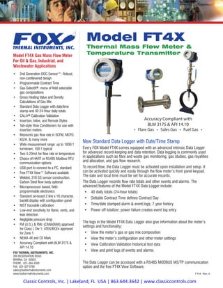
- 1. • 2nd Generation DDC-Sensor™: Robust, non-cantilevered design • Programmable Contract Time • Gas-SelectX®: menu of field selectable gas compositions • Gross Heating Value and Density Calculations of Gas Mix • Standard Data Logger with date/time stamp and 40 24-Hour daily totals • CAL-V® Calibration Validation • Insertion, Inline, and Remote Styles • Tab-style Flow Conditioners for use with insertion meters • Measures gas flow rate in SCFM, MCFD, KG/H, & many more • Wide measurement range: up to 1000:1 turndown; 100:1 typical • Two 4-20mA for flow rate or temperature • Choice of HART or RS485 Modbus RTU communication options • USB port to connect to a PC, standard • Free FT4X View™ Software available • Welded, 316 SS sensor construction, Carbon Steel flow body optional • Microprocessor based, field- programmable electronics • Standard on-board 2 line x 16 character, backlit display with configuration panel • NIST traceable calibration • Low-end sensitivity for flares, vents, and leak detection • Negligible pressure drop • FM (U.S.) & FMc (CANADIAN) approved for Class I, Div 1; ATEX/IECEx approved for Zone 1 • NEMA 4X and CE Mark • Accuracy Compliant with BLM 3175 & API 14.10 New Standard Data Logger with Date/Time Stamp Every FOX Model FT4X comes equipped with an advanced intrinsic Data Logger for advanced record-keeping and data retention. Data logging is commonly used in applications such as flare and waste gas monitoring, gas studies, gas royalities and allocation, and gas flow research. To record flow, the Data Logger must be activated upon installation and setup. It can be activated quickly and easily through the flow meter’s front panel keypad. The date and local time must be set for accurate records. The Data Logger records flow rate totals and other events and alarms. The advanced features of the Model FT4X Data Logger include: • 40 daily totals (24-hour totals) • Settable Contract Time defines Contract Day • Time/date stamped alarm & event logs; 7 year history • Power off totalizer; power failure creates event log entry The logs in the Model FT4X Data Logger also give information about the meter’s settings and functionality: • View the meter’s gas or gas mix composition • View the meter’s configuration and other meter settings • View Calibration Validation historical test data • View and print logs of events and alarms The Data Logger can be accessed with a RS485 MODBUS MS/TP communication option and the free FT4X View Software. Model FT4X Gas Mass Flow Meter For Oil & Gas, Industrial, and Wastewater Applications FT4X Rev. A FOX THERMAL INSTRUMENTS, INC. 399 RESERVATION ROAD MARINA, CA 93933 PHONE: 831-384-4300 FAX: 831-337-5786 sales@foxthermalinstruments.com www.foxthermalinstruments.com Model FT4X Thermal Mass Flow Meter & Temperature Transmitter Accuracy Compliant with BLM 3175 & API 14.10 • Flare Gas • Sales Gas • Fuel Gas • Classic Controls, Inc. | Lakeland, FL USA | 863.644.3642 | www.classiccontrols.com
- 2. Fast and Flexible Gas Flow Measurement Offering you the flexibility to monitor multiple gas types at the push of a button, rotate the housing as needed for tight installations, and configure meter settings from advanced software, the FOX Model FT4X thermal mass flow meter and temperature transmitter can be used in a large variety of Oil & Gas, Industrial, and Wastewater gas flow measurement applications. Theory of Operation FOX Thermal Flow Meters use a constant temperature differential (constant Δ T) technology to measure mass flow rate of air and gases. The thermal mass flow sensor consists of two Resistance Temperature Detectors (RTD’s). The Reference RTD measures the gas temperature. The instrument electronics heat the mass flow sensor, or heated element, to a constant temperature differential (constant Δ T) above the gas temperature and measures the cooling effect of the gas flow. The electrical power required to maintain a constant temperature differential is directly proportional to the gas mass flow rate. The microprocessor linearizes this signal to deliver a linear 4-20mA signal. FOX Model FT4X Thermal Gas Mass Flow Meter Features The FOX Model FT4X measures gas flow rate in standard units without the need for temperature or pressure compensation. It provides two isolated 4-20mA outputs, a pulse/alarm output, a contact input, and optional RS485 Modbus RTU or HART communication options. With a standard on-board 2-line x 16-character, backlit display, operators can view flow rate, total, elapsed time, process gas temperature, and alarms. The display is also used in conjunction with the Configuration Panel to access flow meter settings, such as 4-20mA and pulse output scaling, pipe diameter, low flow cutoff, flow filtering (damping), display options, and high or low alarm limits. The Model FT4X is available in both insertion and inline styles. The insertion probe is easily installed by drilling a hole in the pipe and welding on a 1” NPT coupling. A FOX-supplied compression fitting secures the probe in place. It is supplied with 316 stainless steel wetted materials standard. Inline models are available in 1½” to 6” sizes and inlcudes built-in flow conditioners that eliminate the need for long, straight pipe runs. A USB port to connect to a computer or laptop is standard; interface options include 4-20mA, pulse, HART, and RS485 Modbus RTU. MODEL FT4X Advanced Features Suitable for harsh and hazardous environments, the instrument features: • Robust DDC-Sensor™Design • Gas-SelectX® gas selection menu featuring new Oil & Gas Menu • Data Logger with 40 Daily Totals (24 hour totals) • Settable Contract Time defines Contract Day • Gross Heating Value and Density calculations of gas mix • CAL-V® Calibration Validation • Rotatable probe: allows ±180 degree swivel • FM/FMc, ATEX, IECEx approvals. CE mark. • 10-30VDC power input, standard • NIST-traceable calibration • Free FT4X View™ Software Perfect for Oil & Gas, Industrial, and Wastewater applications, the Model FT4X is the latest instrument offered in the FOX product line. CAL-V® For customers that need a quick and easy way to verify the calibration of the meter in the field, the Model FT4X offers the CAL-V® feature. This feature can be accessed and run through the meter’s standard display and configuration panel, Modbus, or the FT4X View™ Software. The test takes less than 5 minutes to run and produces a pass/fail result at the conclusion of the test. A fail result may indicate either a dirty sensor or the need to recalibrate. If the CAL-V® test is performed using the FT4X View™ software, a Calibration Validation Certificate can be produced at the conclusion of the test. The certificate will show the date and time of the test along with meter data such as firmware version, meter serial number, configuration settings, and currently selected gas/gas mix. This in-situ calibration validation test helps operators comply with environmental mandates and eliminates the cost and inconvenience of annual factory calibration. View historical CAL-V® test data in the log.The FOX 2nd generation DDC Sensor™ eliminates the sensor element vibration which can lead to metal fatigue and failure. The Model FT4X is available with inline flowbodies with built-in flow conditioners. The FT4X is approved for FM/FMc Class I, Division 1, ATEX/IECEx Zone 1. CE Mark. Accuracy compliant with BLM 3175 & API 14.10.
- 3. DDC-Sensor™ The FOX DDC-Sensor™ is the state-of-the-art sensor technology used in the FOX Model FT4X Thermal Gas Flow Meter. The DDC- Sensor™, a Direct Digitally Controlled sensor, is unlike other thermal flow sensors available on the market. Instead of using traditional analog circuitry, the DDC-Sensor™ is interfaced directly to the FT4X microprocessor for more speed and programmability. The DDC- Sensor™ accurately responds to changes in process variables (gas flow rate, pressure, and temperature) to determine mass flow rate, totalized flow, and temperature. FOX’s DDC-Sensor™ provides a technology platform for calculating accurate gas correlations. The FT4X correlation algorithms allow the meter to be calibrated on a single gas in the factory while providing the user the ability to select other gases or gas mixes in the Gas-SelectX® menu. FOX’s Model FT4X with its DDC-Sensor™ and advanced correlation algorithm provides an accurate, multi- gas-capable thermal gas flow meter. Gas-SelectX® Gas Selection Menu Many customers need a fast solution to their monitoring needs. For these cases, FOX has developed the Gas-SelectX® gas selection menu feature for the Model FT4X flow meter. Gas-SelectX® allows the user to choose from a menu of several common gases or gas mixtures for their application. The Gas-SelectX® feature has three gas menus with the following available gases: Pure Gas Menu Mixed Gas Menu O&G Gas Menu Air Air Methane (C1) Argon Argon Ethane (C2) Butane Butane Propane (C3) Carbon Dioxide Carbon Dioxide i-Butane (C4) Methane Methane n-Butane (C4) Natural Gas* Nitrogen Pentanes (C5) Nitrogen Oxygen Hexanes (C6) Oxygen Helium Carbon Dioxide Helium Hydrogen Nitrogen Hydrogen Propane Heptanes (C7) Propane Ethane Octanes (C8) Nonanes+(C9+) *Choosing Natural Gas sets the NAESB average in a pre-programmed mix of methane, ethane, propane, nitrogen, and carbon dioxide. The meter’s proprietary algorithms allow the user to switch gases or gas mixes in the field, as needed. The Pure and Mixed Gas Menus make the FT4X ideal for measurement of digester gas, Liquefied Petroleum Gas (LPG) and a variety of other biogases. With the O&G Menu on the Model FT4X, Gas-SelectX® contains gases common to Oil & Gas applications. Whether you need to measure natural gas, air, flare gas, vent gas, or digester gas, the FT4X brings these options and more to the user with a quick push of a button. FC10 Tab-style Flow Conditioners FOX now offers tab-style flow conditioners for use with insertion meters. Customers want the shorter straight pipe run requirements that you can get from an inline style meter, but often require an insertion style flow meter for the lower cost and the easy installation in tight areas. The FC10 flow conditioners are installed between two flanges upstream of the insertion flow meter and used to correct irregular flow profiles due to elbows or obstructions upstream from the meter’s probe. Use of a flow conditioner helps ensure the highest flow meter accuracy. FT4X View™ Software FOX has developed advanced software - FT4X View™ - a free PC- compatible application available for download from the FOX website. Connect your laptop, PC, or control station to the meter using the USB port interface to access the meter’s data and configure the meter’s settings. FT4X View allows: • Quick access to all configuration parameters and available gas selections • Selection of measurement units, flow and temperature ranges, alarm settings and more • Print a CAL-V Calibration Validation certificate • Display of alarm codes • Storage of meter configurations to a file that can be archived • Raw data to be viewed in order to diagnose or troubleshoot your meter • Data logging to an Excel™ spreadsheet • View Gross Heating Value and Density of gas mix ADVANCED TECHNOLOGY The Model FT4X is available with FC10 Flow Conditioners for use with insertion flow meters.
- 4. Meter Dimensional Drawings Drawings of the Model FT4X meter and retractor dimensions are shown here in inches (mm). DIMENSIONS 2X 3/4IN. NPT, FEMALE INPUT POWER SIGNAL WIRING "HH" "LL" F1 F2 F3 F4 3.9 (9.9) 8.1 (20.6) 5.2 (13.2) 4.6 (11.7) 7.9±.2 (20.1±.5) .73 Dimensions Probe Length “LL” Dim, In(cm) “HH” Dim, In(cm) 6” 6.0 (15.2) 13.9 (35.3) 9” 9.0 (22.9) 16.9 (42.9) 12” 12.0 (30.5) 19.9 (50.5) 15” 15.0 (38.1) 22.9 (58.2) 18” 18.0 (45.7) 25.9 (65.8) 24” 24.0 (61.0) 31.9 (81.0) 30” 30.0 (76.2) 37.9 (96.3) 36” 36.0 (91.4) 43.9 (111.5) F1 F2 F3 F4 9.3±0.3 (23.6±.76) .73" "LL" 7.9±.2 (20.1±.5) 4.6 (11.7) 3.9 (9.9) 8.1 (20.6) 2X 3/4" NPT, FEMALE Ø.75 PROBE (Ø1.90) "HH" Dimensions Retractor “LL” Dim, In(cm) 15R 15.0 (38.1) 18R 18.0 (45.7) 24R 24.0 (61.0) 30R 30.0 (76.2) 36R 36.0 (91.4) Dimensions Pipe Size “L” Dim, In(cm) “H” Dim, In(cm) 1.50” 12.0 (30.5) 10.50 (26.7) 2.00” 12.0 (30.5) 10.50 (26.7) 2.50” 18.0 (45.7) 10.60 (26.9) 3.00” 18.0 (45.7) 10.60 (26.9) Local Styles Local Insertion Meter Local Insertion Meter with Retractor Dimensions Retractor “HH” Dim, In(cm) 15R 22.9 (58.2) 18R 25.9 (65.8) 24R 31.9 (81.0) 30R 37.9 (96.3) 36R 43.9 (111.5) Local Inline Meter with NPT Ends Local Inline Meter with Flanges F1 F2 F3 F4 2x 3/4 inch NPT Female “H” “L” LC 2x NPT Male Thread 4.6 (11.7) 5.2 (13.2) 8.1 (20.6) 4.3 (10.9) Signal Wiring Input Power 2x 3/4 inch NPT Female “H” “L” LC 4.6 (11.7) 5.2 (13.2) 2X Flange, Raised Face, ANSI B16.5, 316 SST 8.1 (20.6) 4.3 (10.9) F1 F2 F3 F4 Dimensions Pipe Size “L” Dim, In(cm) “H” Dim, In(cm) 1.50” 12.0 (30.5) 10.50 (26.7) 2.00” 12.0 (30.5) 10.50 (26.7) 2.50” 18.0 (45.7) 10.60 (26.9) 3.00” 18.0 (45.7) 10.60 (26.9) 4.00” 18.0 (45.7) 11.10 (28.2) 6.00” 24.0 (60.6) 12.20 (31.0)
- 5. DIMENSIONS F1 F2 F3 F4 9.3±0.3 23.6±7.6 .73 "LL" 4.6 (11.7) 3.9 (9.9) 8.1 (20.6) 2X 3/4" NPT, FEMALE 5.2 (13.2) REMOTE ENCLOSURE 4.4 (11.2) 2.0 (5.1) Ø3.6 (Ø9.1) 7.2±.2 (18.3±.5) CONDUIT, 3/4", METAL SHIELDED CABLE, 8-CONDUCTOR, 100FT (30.48m) MAX. Ø.75 PROBE ELECTRONICS ENCLOSURE "HH" 2.81 2.81 Ø2.38 2 IN. PIPE 4x Ø.344 FT4X ENCLOSURE JAM NUT SEE DETAIL ADAPTER BRACKET 2x U-BOLT W/NUT 4x WASHER THREADS PROJECTIONS DETAIL ‘A’ MOUNTING HOLE DETAIL SIDE VIEW FRONT VIEW F1 F2 F3 F4 F1 F2 F3 F4 4.6 (11.7) 3.9 (9.9) 8.1 (20.6) 2X 3/4" NPT, FEMALE 5.2 (13.2) REMOTE ENCLOSURE 4.4 (11.2) 2.0 (5.1) Ø3.6 (Ø9.1) CONDUIT, 3/4", METAL SHIELDED CABLE, 8-CONDUCTOR, 100FT (30.48m) MAX. ELECTRONICS ENCLOSURE 7.2±.2 (18.3±.5) "LL" "HH" .73" 2X 3/4 " NPT, Female 3.6 (9.1)4.4 (11.2) 2.0 (5.1) 4.5 (11.4) “HH” “L” CL Remote Cable, 8 Conductor, Shielded, 100FT Max. 4.6 (11.7) F1 F2 F3 F4 5.2 (13.2) 3.6 (9.1) 4.4 (11.2) 2.0 (5.1) 2.0 (5.1) “HH” Remote Cable, 8 Conductor, Shielded, 100FT Max. “L” LC 2x NPT Male Thread 4.6 (11.7) 5.2 (13.2) Input Power F1 F2 F3 F4 Remote Styles Dimensions Retractor “LL” Dim, In(cm) “HH” Dim, In(cm) 15R 15.0 (38.1) 22.2 (56.4) 18R 18.0 (45.7) 25.2 (64.0) 24R 24.0 (61.0) 31.2 (79.2) 30R 30.0 (76.2) 37.2 (94.5) 36R 36.0 (91.4) 43.2 (109.7) Dimensions Model Code Probe Length “LL” Dim, In(cm) “HH” Dim, In(cm) 06I 6” 6.0 (15.2) 13.2 (33.5) 09I 9” 9.0 (22.9) 16.2 (41.1) 12I 12” 12.0 (30.5) 19.2 (48.8) 15I 15” 15.0 (38.1) 22.2 (56.4) 18I 18” 18.0 (45.7) 25.2 (64.0) 24I 24” 24.0 (61.0) 31.2 (79.2) 30I 30” 30.0 (76.2) 37.2 (94.5) 36I 36” 36.0 (91.4) 43.2 (109.7) Dimensions Pipe Size “L” Dim, In(cm) “H” Dim, In(cm) 1.50” 12.0 (30.5) 10.50 (26.7) 2.00” 12.0 (30.5) 10.50 (26.7) 2.50” 18.0 (45.7) 10.60 (26.9) 3.00” 18.0 (45.7) 10.60 (26.9) Remote Mounting Kit Remote Insertion Meter Remote Insertion Meter with Retractor Remote Inline Meter with NPT Ends Remote Inline Meter with 150# Flanges Inline flow meter features also available: • 300# flanges • Carbon steel flow bodies Dimensions Pipe Size “L” Dim, In(cm) “H” Dim, In(cm) 1.50” 12.0 (30.5) 10.50 (26.7) 2.00” 12.0 (30.5) 10.50 (26.7) 2.50” 18.0 (45.7) 10.60 (26.9) 3.00” 18.0 (45.7) 10.60 (26.9) 4.00” 18.0 (45.7) 11.10 (28.2) 6.00” 24.0 (60.6) 12.20 (31.0)
- 6. Why Choose FOX Thermal Mass Flow Meters Over Other Technologies? For customers searching for a lower cost, higher accuracy low flow measurement meter, thermal mass flow meters by FOX beat DP meters and the other flow technologies on the market today. Compare the new Model FT4X Thermal Mass Flow Meter and Temperature Transmitter equipped with the state-of-art DDC-Sensor Other Technologies Model FT4X Thermal Mass Flow Flow Measurement of gases Other technologies require multiple instruments to determine the volumetric flow rate at reference conditions. Direct mass flow measurement of air and gases in standard volumetric units (ie MSCFD, SCFM, or NM3/H) or mass units (ie LBS/M or KG/H). Each meter has the option for the user to select a variety of flow units (see Operating Specs on p. 8). Pressure or temperature compensation Differential pressure flow meters require pressure and temperature compensation. No additional pressure or temperature compensation is required. This is a time and cost saving measure. No additional calculations or equipment are needed to calculate flow because the meter measures the mass flow rate. Turndown Vortex meters are only suitable for very high flow rates. DP meters do not have good turndown. Repeatability and exceptionally broad measurement range: up to 1000:1 (100:1 typical). Whether the flow is at a very high or low velocity, FOX thermal mass flow meters can measure it. Pressure Drop If a DP meter is used to measure low velocity flow, a very small orifice is required resulting in high pressure drop. Low pressure drop. The pressure drop of a thermal mass flow meter is negligible. Moving Parts A meter with moving parts, like a Turbine meter, will need regular maintenance. No moving parts. Price Ultrasonic meters are especially expensive. Cost effective. Thermal mass flow meters offer a low cost alternative. Installation Some meter technologies are complicated and difficult to install, require additional equipment, or long straight pipe run requirements. Easy to install with insertion and inline configurations. Insertion meters are easy to install, inline meters come equipped with flow conditioners to help reduce the straight run requirements. Communication options available and intrinsic to meter electronics. Operation Most manufacturers build meters for a single purpose, gas calibration, or application. The customer must sift through pages of specs to find the right meter for their application. This is time consuming and ineffective. Microprocessor based, field rangeable electronics. FOX pioneered the use of microprocessors in thermal mass flow meters and continues to create innovative solutions to measurement needs across many industries and applications. Gas-SelectX®, available in the Model FT4X, allows the user to change the gas selection in the field. Displays with configuration panels and free software allow users to interact and program the meter in the field. Using the online Product Configurator, the customer can enter process data into the system for an instant FOX Product recommendation: no need to search a list of meters for the one that’s right for you! technology, new expanded Gas-SelectX® gas selection menu, and a standard Data Logger with date and time stamp as the alternative to other technologies. Then take a look at the other benefits FOX gas mass flow meters offer over other flow measurment technologies... COMPARISONS
- 7. Choose Your Meter’s Features The Model FT4X is available in insertion, inline, and remote styles. The insertion meter is easily installed with a weld-o-let and compression fitting and requires straight pipe runs of 15D upstream/10D downstream. The inline model is available in 1½” to 6” sizes and includes built-in flow conditioners that eliminate CONFIGURATIONS the need for long, straight pipe runs. Straight run requirements are decreased to 8D upstream/4D downstream for the inline style meters. FC10 Flow Conditioners are available for insertion style meters and further reduce the straight run requirements. In a remote configuration, the electronics can be mounted up to 100’ from the sensor. APPROVALS Approvals CE Mark: Approved EMC Directive: 2014/30/EU Electrical Equipment for Measurement, Control, and Lab Use: EN61326-1:2013 FM (U.S.) & FMc (CANADA): Approved Class I, Division 1, Groups B, C, D; Class II, Division 1, Groups E, F, G; and Class III, Division 1; T4, Ta = -40˚ to 70˚C; Class I, Zone 1, AEx/Ex db IIB + H2 T4; Gb Ta = -40˚C to 70˚C; Type 4X, IP67 ATEX (FM16ATEX0013X): Approved II 2 G Ex db IIB + H2 T4; Gb Ta = -40˚C to 70˚C; IP67 II 2 D Ex tb IIIC T135˚C; Db Ta = -40˚C to 70˚C; IP67 IECEx (IECEx FMG 16.0010X): Approved Ex d IIB + H2 T4; Gb Ta = -40˚C to 70˚C; IP67 Ex tb IIIC T135˚C; Db Ta = -40˚C to 70˚C; IP67 ATEX and IECEx Standards: EN 60079-0:2012 + A11:2013 IEC 60079-0:2011 EN 60079-1:2014 IEC 60079-1:2007 EN 60079-31:2014 IEC 60079-31:2008 EN 60529:1991 + A1:2000 IEC 60529:2001 Thermal Mass Flow Meter & Temperature Transmitter Feature 1A : Insertion Sensor Insertion meter with 6-inch probe Insertion meter with 9-inch probe Insertion meter with 12-inch probe Insertion meter with 15-inch probe Insertion meter with 18-inch probe Insertion meter with 24-inch probe Insertion meter with 30-inch probe Insertion meter with 36-inch probe 15" Probe w/ 125 PSI retractor & full port valve - 3/4" male NPT, 316 SS wetted parts 18" Probe w/ 125 PSI retractor & full port valve - 3/4" male NPT, 316 SS wetted parts 24" Probe w/ 125 PSI retractor & full port valve - 3/4" male NPT, 316 SS wetted parts 30" Probe w/ 125 PSI retractor & full port valve - 3/4" male NPT, 316 SS wetted parts 36" Probe w/ 125 PSI retractor & full port valve - 3/4" male NPT, 316 SS wetted parts 1.5 inch, male npt ends (schedule 40) 12" Face-to-face 2 inch, male npt ends (schedule 40) 12" Face-to-face * (*20PC for Carbon Steel) 2.5 inch, male npt ends (schedule 40) 18" Face-to-face * (*25PC for Carbon Steel) 3 inch, male npt ends (schedule 40) 18" Face-to-face * (*30PC for Carbon Steel) 1.5 inch, 150# RF flanges (schedule 40) 12" Face-to-face 2 inch, 150# RF flanges (schedule 40) 12" Face-to-face * (*20FC for Carbon Steel) 2.5 inch, 150# RF flanges (schedule 40) 18" Face-to-face * (*25FC for Carbon Steel) 3 inch, 150# RF flanges (schedule 40) 18" Face-to-face * (*30FC for Carbon Steel) 4 inch, 150# RF flanges (schedule 40) 18" Face-to-face * (*40FC for Carbon Steel) 6 inch, 150# RF flanges (schedule 40) 24" Face-to-face * (*60FC for Carbon Steel) 2 inch, 300# RF flanges (schedule 40) 12" Face-to-face * (*20FC for Carbon Steel) 2.5 inch, 300# RF flanges (schedule 40) 18" Face-to-face * (*25FC for Carbon Steel) 3 inch, 300# RF flanges (schedule 40) 18" Face-to-face * (*30FC for Carbon Steel) 4 inch, 300# RF flanges (schedule 40) 18" Face-to-face * (*40FC for Carbon Steel) 6 inch, 300# RF flanges (schedule 40) 24" Face-to-face * (*60FC for Carbon Steel) Local NEMA 4X enclosure, 24VDC powered Remote with explosion - proof sensor J-box, 24VDC powered, 100' max, cable optional No communication option RS485 Modbus MS/TP HART on primary 4-20mA output Parent Model No. Feature 1B : Inline Flow Body (316 Stainless steel flowbody) *Available in A106 Grade B Carbon steel pipe Feature 2: Enclosure and Power Feature 3: Communication Options E3 Parent Model Feature 1 Feature 3 36I 15R B0 15P 20P 25P 30P FT4X 18R 24R 20F 25F E1 60G 30R 36R Feature 2 06I 09I 12I 15I 18I 24I 30I 30F 15F 20G 25G 30G 40G 40F 60F RS BH
- 8. SPECIFICATIONS Performance Specs Flow Accuracy: Air: ±1% of reading ±0.2% of full scale Other gases: ±1.5% of reading ±0.5% of full scale Accuracy specification applies to customer’s selected flow range Maximum range: 15 to 60,000 SFPM (0.07 to 280 NMPS) Minimum range: 15 to 1,000 SFPM (0.07 to 4.7 NMPS) Straight, unobstructed pipe requirement: Insertion: 15 diameters upstream 10 downstream Inline: 8 diameters upstream, 4 downstream Flow Repeatability: ±0.2% of full scale Flow Response Time: 0.8 seconds (one time constant) Temperature Accuracy: ±1° F (±0.6° C) Calibration: Factory Calibration to NIST traceable standards CAL-V®: In-situ, operator-initiated calibration validation Operating Specs Gas-SelectX® Gas Selections: Pure Gas, Mixed Gas, and Oil & Gas Mixed Gas Menus to suit any application. See the FOX website for more information on availability of current gases. Units of Measurement: SCFM, SCFH, NM3/M, NM3/H, NM3/D, NLPS, NLPM, NLPH, MCFD, MSCFD, SCFD, MMSCFD, MMSCFM, SM3/D, SM3/H, SM3/M, LB/S, LB/M, LB/H, LB/D, KG/S, KG/M, KG/H, SLPM, MT/H Gas Pressure (maximum; at 100°F): Insertion meter: 740 psig (51.02 barg)* Inline meter: NPT 500 psig (34.5 barg); 150# flange 230 psig (16 barg); 300# flange 600 psig (41.4 barg) Retractor: 150 psig (10.3 barg) Check with factory for higher pressure options. *NOTE! When teflon ferrule option ordered, gas pressure is 60psig (4.1 barg) maximum. Relative Humidity: 90% RH maximum; non-condensing NOTE! Condensing liquids contacting the sensor can cause erratic flow indication. Temperature: DDC-Sensor™: -40 to 250°F (-40 to 121°C) Enclosure: -40 to 158°F (-40 to 70°C)* Remote Sensor Enclosure: -40 to 158°F (-40 to 70°C) *NOTE! Display dims below -4˚F (-20˚C); function returns once temperature rises again. Flow Velocity Range: 15 to 60,000 SFPM (0.07 to 280 NMPS) Turndown: up to 1000:1; 100:1 typical Flow Ranges - Insertion Meters Pipe Diameter SCFM MSCFD NM3/Hr 1.5" (40mm) 0 - 840 0 - 1,220 0 - 1,325 2" (50mm) 0 - 1,400 0 - 2,020 0 - 2,210 3" (80mm) 0 - 3,100 0 - 4,440 0 - 4,890 4” (100mm) 0 - 5,300 0 - 7,650 0 - 8,360 6" (150mm) 0 - 12,000 0 - 17,340 0 - 18,930 8" (200mm) 0 - 20,840 0 - 30,020 0 - 32,870 10" (250mm) 0 - 32,800 0 - 47,250 0 - 51,740 12" (300mm) 0 - 46,600 0 - 67,180 0 - 73,500 NOTE! To determine if the FT4X will operate accurately in other pipe sizes, divide the maximum flow rate by the pipe area. The application is acceptable if the resulting velocity is within the velocity range above. Check FOX website for velocity calculator. Dimensional Probe diameter: ¾” Equation for selecting flow meter probe length: Probe length = ½ pipe ID (in inches) + 3” + 10” (for retractor, if any) + thickness of insulation (if any). Round up to the next standard probe length available. Flow Ranges - Inline Meters Pipe Diameter SCFM MSCFD NM3/Hr 1.5" (40mm) 0 - 840 0-1,220 0 - 1,320 2" (50mm) 0 - 1,400 0-2,020 0 - 2,204 2.5” (63mm) 0 - 2,000 0-2,880 0 - 3,150 3" (80mm) 0 - 3,100 0-4,440 0 - 4,890 4” (100mm) 0 - 5,300 0-7,650 0 - 8,360 6" (150mm) 0 - 12,000 0-17,340 0 - 18,930 NOTE! Consult factory for flow ranges above those listed. Inline meters above 5,000 SCFM (7,900 NM3/H) air may require third party calibration. Contact Fox. Input power: 12 to 28 VDC, 6 watts max. Full input power range: 10 to 30 VDC. A 20 Watt or greater power supply is recommended to power the FT4X Class I Equipment (Electrical Grounding Required for Safety). Installation (Over-voltage) Category II for transient over-voltages. Inputs/Outputs: 4-20mA Channel 1: • Standard isolated 4-20mA output configured to indicate for flow; fault indication per NAMUR NE43. HART communication option. The 4-20mA load resistance must be 125 ohms or less when operating on 12 volt power and 600 ohms or less on 24 volt power. 4-20mA Channel 2: • Standard isolated 4-20mA output configured to indicate either flow or temperature. Pulse/Alarm: • Isolated open collector output rated for 5 to 24VDC, 10mA maximum load, 0 to 100Hz (the pulse output can be config- ured to either transmit a 0 to 100Hz signal proportional to flow rate or an on/off alarm). Remote Switch Input: • Can be configured to reset the flow totalizer and elapsed time. Serial Communication: • Isolated RS485 Modbus RTU option • Isolated HART communication option USB Communication: • Isolated USB 2.0 for interfacing with a laptop or computer is standard. • FT4X View™: A free PC-based software tool that provides complete configuration, remote process monitoring, and data logging functions through USB communication. 4-20mA and Loop Verification: Simulation mode used to align 4-20mA output with the input to customer’s PLC/DCS. Physical Specs Sensor Material: 316 stainless steel Enclosure: NEMA 4X (IP67), aluminum, dual ¾” FNPT conduit entries. Cabling to remote enclosure: 8-conductor, 18 AWG, twisted, shielded, 100 feet maximum. Insertion flow meter installation: Fox-supplied compression fitting connects to customer-supplied 1” female coupling welded to pipe. FOX recommends the following probe lengths (without insulation): Pipe Diameter Probe Length 1.5" (40mm) to 6" (150mm) 6-inch 8" (200mm) to 12" (300mm) 9-inch 14" (350mm) to 18" (450mm) 12-inch Probe Lengths (LL*) in inches(cm) = 6.0 (15.2) 9.0 (22.9) 12.0 (30.5) 15.0 (38.1) 18.0 (45.7) 24.0 (61.0) 30.0 (76.2) 36.0 (91.4) *See dimensional drawings on pages 4 and 5.