Filters for Electromagnetic Compatibility Applications
Stepper motor
1. APPLICATION NOTE
AN235/0788
STEPPER MOTOR DRIVING
By H. SAX
From a circuit designer’s point of view stepper mo-
tors can be divided into two basic types : unipolar
and bipolar.
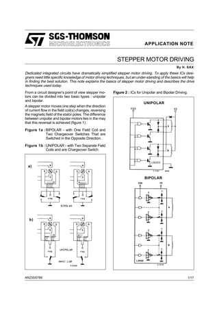
A stepper motor moves one step when the direction
of current flow in the field coil(s) changes, reversing
the magnetic field of the stator poles. The difference
between unipolar and bipolar motors lies in the may
that this reversal is achieved (figure 1) :
Figure 1a :BIPOLAR - with One Field Coil and
Two Chargeover Switches That are
Switched in the Opposite Direction.
Figure 1b :UNIPOLAR - with Two Separate Field
Coils and are Chargeover Switch.
Figure 2 : ICs for Unipolar and Bipolar Driving.
UNIPOLAR
a)
b)
BIPOLAR
Dedicated integrated circuits have dramatically simplified stepper motor driving. To apply these ICs desi-
gners need little specific knowledge of motor driving techniques, but an under-standing of the basics will help
in finding the best solution. This note explains the basics of stepper motor driving and describes the drive
techniques used today.
1/17
2. The advantage of the bipolar circuit is that there is
only one winding, with a good bulk factor (low win-
ding resistance). The main disapuantages are the
two changeover switches because in this case more
semiconductors are needed.
The unipolar circuit needs only one changeover
switch. Its enormous disadvantage is, however, that
a double bifilar winding is required. This means that
at a specific bulk factor the wire is thinner and the
resistance is much higher. We will discuss later the
problems involved.
Unipolar motors are still popular today because the
drive circuit appears to be simpler when implemen-
ted with discrete devices. However with the integra-
ted circuits available today bipolar motors can be
driver with no more components than the unipolar
motors. Figure 2 compares integrated unipolar and
bipolar devices.
BIPOLAR PRODUCES MORE TORQUE
The torque ofthesteppermotorisproportional tothe
magnetic field intensity of the stator windings. It may
be increased only by adding more windings or by in-
creasing the current.
A natural limit against any current increase is the
danger of saturating the iron core. Though this is of
minimal importance. Much more important is the
maximum temperature rise of the motor, due to the
power loss in the stator windings. This shows one
advantage of the bipolar circuit, which, compared to
unipolar systems, has only half of the copper resi-
stance because of the double cross section of the
wire. The winding current may be increased by the
factor √2 and this produces a direct proportional af-
fect on the torque. At their power loss limit bipolar
motors thus deliver about 40 % more torque (fig. 3)
than unipolar motors built on the same frame.
If a higher torque is not required, one may either re-
duce the motor size or the power loss.
Figure 3 : Bipolar Motors Driver Deliver More
Torque than Unipolars.
CONSTANT CURRENT DRIVING
In order to keep the motor’s power loss within a rea-
sonable limit, the current in the windings must be
controlled.
Asimpleandpopularsolutionisto giveonlyasmuch
voltage as needed, utilizing the resistance (RL) of
the winding to limit the current (fig. 4a). Amore com-
plicated but also more efficient and precise solution
is the inclusion of a current generator (fig. 4b), to
achieve independence from the winding resistance.
The supply voltage in Fig. 4b has to be higher than
the one in Fig. 4a. A comparison between both cir-
cuits in the dynamic load/working order shows visi-
ble differences.
Figure 4 : Resistance Current Limiter(a) and Cur-
rent Generator Limiting.
Figure 5 : At High Step Frequencies the Winding
Current cannot Reach its Setting Value
because of the Continuous Direction
Change.
APPLICATION NOTE
2/17
3. It has already been mentioned that this power of the
motor is, among others, proportional to the winding
current.
In the dynamic working order a stepper motor chan-
ges poles of the winding current in the same stator
winding after two steps. The speed with which the
current changes its direction in the form of an expo-
nential function depends on the specified inductan-
ce, the coil resistance and on the voltage. Fig. 5a
shows that at a low step rate the winding current IL
reaches its nominal value VL/RL before the direction
is changed. However, if the poles of the stator win-
dings are changed more often, which corresponds
to a high step frequency, the current no longer rea-
ches its saturating value because of the limited
change time ; the power and also the torque dimi-
nish clearly at increasing number of revolutions (fig.
5).
MORE TORQUE AT A HIGHER NUMBER
OF REVOLUTIONS
Higher torque at faster speeds are possible if a cur-
rent generator as shown in Fig. 4b is used. In this
applicationthe supplyvoltageischosen ashighpos-
sible to increase the current’s rate of change. The
current generator itself limits only the phase current
and becomes active only the moment in which the
coil current has reached its set nominal value. Up to
this value the current generator is in saturation and
the supply voltage is applied directly to the winding.
Fig. 6, shows that the rate of the current increase is
now much higher than in Figure 5. Consequently at
higher step rates the desired current can be main-
tained in the winding for a longer time. The torque
decrease starts only at much higher speeds.
Fig. 7 shows the relation between torque and speed
in the normal graphicscheme,typical forthe stepper
motor. It is obvious that the power increases in the
upper torque range where it is normally needed, as
the load to be driven draws most energy from the
motor in this range.
EFFICIENCY - THE DECISIVE FACTOR
The current generator combined with the high sup-
ply voltage guarantees that the rate of change of the
current in the coil is sufficiently high.
At the static condition or at low numbers of revolu-
tions, however, this means thatthe power lossin the
current generator dramatically increases, although
the motor does not deliver any more energy in this
range ; the efficiency factor is extremely bad.
Help comes from a switched current regulation
using the switch-transformer principle, as shown in
fig. 8. The phase winding is switched to the supply
voltage until the current, detected across RS, rea-
ches the desired nominal value. At that moment the
switch, formerly connected to + VS, changes posi-
tion and shorts out the winding. In this way the cur-
rent is stored, but it decays slowly because of inner
winding losses. The discharge time of the current is
determined during this phase by a monostable or
pulse oscillator. After this time one of the pole chan-
ging switches changes back to + VS, starting an in-
duction recharge and the clock-regulation-cycle
starts again.
Figure 6 : With a Step Current Slew, it is not a
Problem to Obtain, even at High Step
frequencies Sufficient Current in Wind-
ings.
Figure 7 : Constant Current Control of the Step-
per Motor Means more Torque at High
Frequency.
Since the only losses in this technique are the satu-
APPLICATION NOTE
3/17
4. ration loss of the switch and that of the coil resistan-
ce, the total efficiency is very high.
The average current that flows from the power sup-
ply line is less than the winding current due to the
concept of circuit inversion. In this way also the po-
wer unit is discharged. This king of phase current
control that has to be done separately for each mo-
tor phase leads to the best ratio between the sup-
plied electrical and delivered mechanical energy.
POSSIBLE IMPROVEMENTS OF THE UNI-
POLAR CIRCUIT
It would make no sense to apply the same principle
to a stabilized current controlled unipolar circuit, as
two more switches per phase would be necessary
for the shortening out of the windings during the free
phase and thus the number of components would
be the same as for the bipolarcircuit ; and moreover,
there would be the well known torque disadvantage.
From the economic point of view a reasonable and
justifiable improvement is the "Bi-Level-Drive"
(fig. 9). Thiscircuitconceptworkswith twosupplyvol-
tages ; with every new step of the motor both win-
dings are connected for a short time to a high supply
voltage. This considerably increases the current rate
of change and its behaviour corresponds more or
less to the stabilized power principle. After a pre-de-
termined the switch opens, a no a lower supply volt-
age is connected to the winding thru a diode.
This kind of circuit by no means reaches the perfor-
mance ofthe clocked stabilized powercontrol asper
fig. 8, as the factors : distribution voltage oscillation,
B.e.m.f., thermal winding resistance, as well as the
separate coil current regulation are not considered,
but it is this circuit that makes the simple unipolar
R/L-control suitable for many fields of application.
Figure 8 : With Switch Mode Current Regulation Efficiency is Increased.
APPLICATION NOTE
4/17
5. Figure 9 : At Every New Step of the Motor, it is Possible to Increase the Current Rate with a Bilevel Circuit.
ADVANTAGES AND DISADVANTAGES OF
THE HALF-STEP
An essential advantage of a stepper motor opera-
ting at half-step conditions is its position resolution
increased by the factor 2. From a 3.6 degree motor
you achieve 1.8 degrees, which means 200 steps
per revolution.
Thisis not alwaysthe onlyreason.Often you are for-
ced to operate at half-step conditions in order to
avoid that operations are disturbed by the motor re-
sonance. These may be sostrong thatthemotorhas
no more torquein certain stepfrequencyrangesand
looses completely its position (fig. 10). This is due
to the fact that the rotor of the motor, and the chan-
ging magnetic field of the stator forms a spring-
mass-system that may be stimulated to vibrate. In
practice, the loadmightdeaden thissystem,butonly
if there is sufficient frictional force.
Inmostcaseshalf-step operation helps, asthe cour-
se covered by the rotor is only half as long and the
system is less stimulated.
The fact that the half-step operation is not the domi-
nating or general solution, depends on certain di-
sadvantages :
- the half-step system needs twice as many
clock-pulses as the full-step system ; the
clock-frequency is twice as high as with the
full-step.
- in the half-step position the motor has only
about half of the torque of the full-step.
Figure 10 :The Motor has no More Torque in Cer-
tain Step Frequency Ranges with Full
Step Driving.
Forthisreasonmanysystemsuse thehalf-stepope-
ration only if the clock-frequency of the motor is wi-
thin the resonance risk area.
The dynamic loss is higher the nearer the load mo-
ment comes to the limit torque of the motor. This ef-
fect decreases at higher numbers of revolutions.
APPLICATION NOTE
5/17
6. TORQUE LOSS COMPENSATION IN THE
HALF-STEP OPERATION
It’s clear that, especiallyin limit situations, the torque
loss in half-step is a disadvantage. If one has to
choose the next larger motor or one with a double
resolution operating in full-step because of some in-
sufficienttorque percentages, itwillgreatlyinfluence
the costs of the whole system.
In this case, there is an alternative solution that does
not increase the coats for the bipolar chopping sta-
bilized current drive circuit.
The torque loss in the half-step position may be
compensated for by increasing the winding current
by the factor √2 in the phase winding that remains
active. This is also permissible if, according to the
motor data sheet, the current limit has been rea-
ched,because thislimitrefers alwaysto the contem-
porary supply with current in both windings in the
full-step position. The factor √2 increase in current
doubles the stray power of the active phase. The
toal dissipated power is like that of the full-step be-
cause the non-active phase does not dissipate po-
wer.
The resulting torque in the half-step position
amounts to about 90 % of that of the full-step, that
means dynamically more than 95 % torque compa-
red to the pure full-step ; a neglectable factor.
The only thing to avoid is stopping the motor at limit
current conditions in a half-step position because it
would belike a winding thermalphaseoverloadcon-
centrated in one.
The best switch-technique for the half-step phase
current increase will be explained in detail later on
Fig. 11 shows the phase current of a stepping motor
in half-step control with an without phase current in-
crease and the pertinent curves of stap frequency
and torque.
Figure 11 :Half Step Driving with Shaping Allows
to Increase the Motor’s Torque to
about 95 % of that of the Full Step.
APPLICATION NOTE
6/17
7. Figure 12 :Only Two Signals for Full Step Driving are Necessary while Four (six if three-state is needed
on the output stages) for half Step.
APPLICATION NOTE
7/17
8. DRIVE SIGNALS FOR THE MICRO ELEC-
TRONIC
A direct current motor runs by itself if you supply if
with voltage, whereas the stepping motor needs the
commutation signal in for of several separated but
linkable commands. In 95 % of the applications to-
day, the origin of these digital commands is a micro-
processor system.
Initssimplestform, a full-stepcontrolneedsonlytwo
rectangular signals in quadrature. According to
which phase is leading, the motor axis rotates clock-
wise or counter-clockwise, whereby the rotation
speed is proportional to the clock frequency.
In the half-step system the situation becomes more
complicated. The minimal two control signals beco-
me four control signals. In some conditions as many
as six signals are needed. If the Tri-state-command
for the phase ranges without current, necessary for
high motor speeds, may not be obtained from the 4
control signals. Fig. 12 shows the relationship be-
tween the phase current diagram and the control si-
gnal for full and half-step.
Since all signals in each mode are in defined rela-
tions with each other, it is possible to generate them
using standard logic. However, if the possibility to
choose full and half-step is desired, a good logic im-
plementation becomes quite expensive and an ap-
plication specific integrated circuit would be better.
Such an application specific integrated circuit could
reduce the numberofoutputsrequired froma micro-
processor from the 6 required to 3 static and dyna-
mic control line.
A typical control circuit that meets all these require-
ments is the L297 unit (fig. 13).
Four signals control the motor in all operations :
1. CLOCK : The clock signal, giving the step-
ping command
2. RESET : Puts the final level signals in a de-
fined start position
3. DIRECTION :Determines the sense of rotation of
the motor axis.
4. HALF/FULL : Desides whether to operate in full
or in half-step.
Another inhibit input allows the device to switch the
motor output into the Tri-state-mode in order to pre-
vent undesiredmovementsduringundefined opera-
ting conditions, such as those that could occur
during.
Figure 13 : The L297 avoids the Use of Complicated Standard Logic to Generate Both Full and Half-step
Driving Signals Together with Chopper Current Control.
RS1 RS2 = 0.5 Ω
VF ≤ 1.2 V @ i = 2A
D1 to D8 = 2 A fast diodes {trr ≤ 200 ns
APPLICATION NOTE
8/17
9. SWITCH-MODE CURRENT REGULATION
The primary function of the current regulation circuit
is to supply enough current to the phase windings
of the motor, even at high step rates.
The functionalblocksrequired fora switchmodecur-
rent control are the same blocks required in swit-
ching power supplies ; flip-flops, comparators ; and
an oscillator are required. These blocks can easily
be included in the same IC that generatesthe phase
control signals. Let us consider the implementation
of chopper current control in the L297.
The oscillator on pin 16 of the L297 resets the two
flip-flops at the start of each oscillator period. The
flip-flop outputs are then combined with the outputs
of the translator circuit to form the 6 control signals
supplied to the power bridge (L298).
When activated, by the oscillator, the current in the
winding will raise, following the L/R time constant
curve,untilthe voltage acrossthe senseresistor(pin
1, 15 of L298) is equal to the reference voltage input
(pin 15, L297) the comparator then sets the flip-flop,
causing the output of the L297 to change to an equi-
phase condition, thus effectively putting a short cir-
cuit across the phase winding. The bridge is
activated into a diagonally conductive state when
the oscillator resets the flip-flop at the start of the
next cycle.
Using a common oscillator to control both current re-
gulators maintains the same choppingfrequency for
both, thus avoiding interference between the two.
Thefunctional blockdiagramoftheL297andthepo-
wer stage (L298) are shown in Figure 14 alone with
the operating wave forms.
An important characteristicsofthiscircuit implemen-
tation is that, during the reset time, the flip-flops are
kept reset. The reset time can be selected by selec-
ting the impedance of the R/C network or pin 16. In
this way, the current spike and noise acrossthe sen-
se resistors that may occur during switching will not
cause a premature setting of the flip-flop. Thus the
recovery current spike of the protection diodes can
be ignored and a filter in the sense line is avoided.
THE RIGHT PHASE CURRENT FOR EVE-
RY OPERATING CONDITION
The Chopper principle of the controller unit reveals
that the phase current in the motor windings is con-
trolled by two data : the reference voltage at pin 15
of thecontrollerand the valueof the sense resis-tan-
ce at pins 1 and 15 of the L298, that is IL = VREF/RS.
By changing VREF it is very easy to vary the current
within large limits.Theonlyquestion isforwhichpur-
pose and at which conditions.
More phase current means more motor torque, but
also higher energy consumption.
An analysis of the torque consumption for different
periods and load position changes shows that there
is no need for different energies.
There is a high energy need during the acceleration
or break phases, whereas during continuous opera-
tion or neutral or stop position less energy has to be
supplied. A motor with its phase current continuou-
sly oriented at the load moment limit, even with the
load moment lacking,consumesneedlesslyenergy,
that is completely transformed into heat.
Therefore it is useful to resolve the phase current in
at least two levels controllable from the processor.
Fig. 18 shows a minimal configuration with two re-
sistance and one small signal transistor as change-
over switch for the reference input. With another
resistance and transistor it is possible to resolve 2
Bits and consequently 4 levels. That is sufficient for
all imaginable causes.
Fig. 16 shows a optimal phase current diagram du-
ring a positioning operation.
APPLICATION NOTE
9/17
10. Figure 14 : Two ICs and very Few External Components Provide Complete Microprocessor to Bipolar Step-
per Motor Interface.
APPLICATION NOTE
10/17
11. Figure 15 : Because of the Set-dominant Latch Inside the L297 it is Possible to Hide Current Spikes and
Noise Across the Sense Resistors thus Avoiding External Filters.
Figure 16 : More Energy is needed During The Acceleration and break Phases Compared the Continuous
Operation, Neutral or Stop Position.
APPLICATION NOTE
11/17
12. HIGH MOTOR CLOCK RESETS IN THE
HALF-STEP SYSTEM
In the half-step position one ofthe motorphases has
to be without current. If the motor moves from a full-
step position into a half-step position, this means
that one motor winding has to be completely di-
scharged. From the logic diagram this means for the
high level bridge an equivalent status of the input si-
gnals A/B, for example in the HIGH-status. For the
coil this means short circuit (fig. 17 up) and conse-
quentlya low reduction ofthe current. Incase ofhigh
half-step speeds the short circuit discharge time
constant of the phase winding is not sufficient to di-
scharge the current during the short half-step pha-
ses. The current diagram is not neat, the half step
is not carried out correctly (fig. 17 center).
For this reason the L297 controller-unit generates
an inhibit-command for each phase bridge, that
switches the specific bridge output in the half-step
position into Tri-state. In this way the coil can start
swinging freely over the external recovery diodes
and discharge quickly. The current decrease rate of
change corresponds more or less to the increase
rate of change (fig. 17 below).
In case of full-step operation both inhibit-outputs of
the controller (pin 5 and 8) remain in the HIGH-sta-
tus.
Figure 17 :The Inhibit Signal Turns Off Immediately the Output Stages Allowing thus a Faster Current De-
cay (mandatory with half-step operation).
APPLICATION NOTE
12/17
13. Figure 18 :With This Configuration it is Possible to Obtain Half-step with Shaping Operation and Therefore
More Torque.
MORE TORQUE IN THE HALF-STEP POSI-
TION
A topic that has already been discussed in detail. So
we will limit our considerations on how it is carried
out, in fact quite simply because of the reference
voltage controlled phase current regulation.
With the help of the inhibit-signals at outputs 5 and
8 of the controller, which are alternatively active only
when the half-step control is programmed, the ref-
erence voltage is increased by the factor 1.41 with
a very simple additional wiring (fig. 18), as soon as
one of the two inhibit-signals switches LOW. This in-
creases the current in the active motorphase pro-
portionally to the reference voltage and
compensates the torque loss in this position. Fig. 19
shows clearly that the diagram of the phase current
is almost sinusoidal, in principle the ideal form of the
current graph.
To sum up we may say that this half-step version of-
fers most advantages. The motor works with poor
resonance and a double position resolution at a
torque, that is almost the same as that of the full-
step.
BETTER GLIDING THAN STEPPING
Ifa stepper motor issupposed to workalmost gliding
and not step by step, the form of the phase current
diagram has to be sinusoidal.
The advantages are very important :
- no more phenomena of resonance
- drastic noise reduction
- connected gearings and loads are treated
with care
- the position resolution may be increased fur-
ther.
However, the use of the L297 controller-unit descri-
bed until now is no longer possible of the more sem-
plicated form of the phase current diagram the
Controller may become simpler in its functions.
Fig. 20 shows us an example with the L6505 unit.
This IC contains nothing more than the clocked pha-
se current regulation which works according to the
same principle as L297. The four control signals
emitting continuously a full-step program are now
generated directlybythe microprocessor.Inorderto
obtain a sinusoidal phase current course the refer-
ence voltage inputs of the Controller are modulated
with sinusoidal half-waves.
The microprocessor that controls the direction ofthe
current phase with the control signals also genera-
tes the two analog signals.
For many applications a microprocessor with dedi-
cated digital to analog converters can be chosen.
Eliminating the need for separate D/A circuits.
About 5 bit have proved to be the most suitable sud-
APPLICATION NOTE
13/17
14. Figure 19 :The Half-step with Shaping Positioning is Achieved by Simply Changing Reference Voltages.
division of the current within one full-step. A higher
resolution brings no measurable advantages. On
the contrary, the converter clock frequency is alrea-
dy very high in case of low motor revolutions and
very difficult to process by the processor-software.
It is recommended to reduce the D/A resolution at
high step frequencies.
In case of higher motor revolutions it is more conve-
nient to operate only in full-step, since harmonic
control is no longer an advantage as the current has
only a triangular waveform in the motor winding.
PRECISION OF THE MICRO STEP
Any desired increase of the position resolution be-
tween the full step position has its physical limits.
Those who think it is possible to resolve a 7.2° -
stepper motor to 1.8° with the same precision as a
1.8° - motor in full-step will be received, as there are
several limits :
The rise rate of the torque diagram corresponding
to the twisting angle of the rotor for the 7.2° - motor
is flatter by a factor of 4 then for the original 1.8° -
motor. Consequently with friction or load moment,
the position error is larger (fig. 21).
For most of the commercial motors there isn’t a suf-
ficiently precise, linear relationship between a sinu-
soidal-current-diagram and an exact micro step
angle. The reason is a dishomogeneous magnetic
field between the rotor and the two stator fields.
Above all, problems have to be expected with mo-
tors with high pole feeling. However, there are spe-
cial stepper motors in which an optimized micro step
operation has already been considered during the
construction phase.
APPLICATION NOTE
14/17
15. Figure 20 :L6506 Unit Gives The Possibility to Modulate Separately the Two Reference Voltage Inputs in
Order to obtain a Sinusoidal Phase Current.
APPLICATION NOTE
15/17
16. Figure 21 :Better Resolution is achieved with Low Degree Motor but More torque is delivered with high
Degree Motor.
CONCLUSIONS
The above described application examples of mo-
dern integrated circuits show that output and effi-
ciency of stepper motors may be remarkably
increased without any excessive expense increase
like before.
Working in limit areas, where improved electronics
with optimized drive sequencesallow the use of less
expensive motors,itiseven possible to obtain acost
reduction.
APPLICATION NOTE
16/17