
Recommended
More Related Content
What's hot
What's hot (20)
Viewers also liked
Similar to Vocational Training Report ( Sealdah Power House)
Similar to Vocational Training Report ( Sealdah Power House) (20)
Recently uploaded
Recently uploaded (20)
Vocational Training Report ( Sealdah Power House)
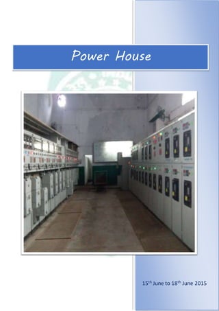
- 1. 15th June to 18th June 2015 Power House
- 2. 4 PowerHouse Introduction: A substation is a part of an electrical generation, transmission and distribution system. Substations transform voltage from high to low or reverse or any of several other important functions. Electric power may flow through several substations between generating plant and consumer and its voltage may change in several steps. A substation has a step up transformer which increase the voltage while decreasing the current while a step down transformer decrease the voltage while increasing the current for domestic and commercial distribution .The word substation comes from the days before the distribution system became a grid. The first substation were connected to only one power station, where the generators were housed and were subsidiaries of that power station. 6 KV. Distribution System in Sealdah Area Sealdah Power House LT Distribution system
- 3. 5 PowerHouse In SEALDAH POWERHOUSEthe control is divided into two sections. i. The Low Tension section ii. The High Tension section The main components of the Power House : Switch Gear Transformers (300KVA. & 500 KVA.) Isolator Bus Bar Bus Coupler Circuit breakers (Air circuit breakers on L.T. side & vacuumcircuit breakers on H.T. side) Relays (Earth Fault Relay & Over CurrentRelay) Hooter / Alarm The components are described in brief fromthe power housebellow. Switch Gear: It is a combination of electrical disconnect switches, fuses and circuit breakers used to control, protect and isolate electrical equipment. This switchgear is connected to the incoming supply from CESC. There are two connections available (one kept for emergency). Incoming Switch Gear The connections are coupled together by a Bus coupler and then sent to the Transformers for further step down of voltage, as required. If any fault occurs upstream (i.e., in supply side), this switchgear immediately disconnects from
- 4. 6 PowerHouse the supply thereby preventing further spreading of fault and hence keeping alive the essential railway operations. Step down transformer: A transformer is a device that transfers electric energy from one circuit to another circuit through inductively coupled conductors---the transformers coil---a varying current in the first or primary winding creates a varying magnetic flux in the transformer core and thus a varying magnetic field through the secondary winding. This varying magnetic field induces a varying electromotive force (EMF) or voltage in the secondary winding. This effect is called mutual induction. If a load is connected to the secondary, an electric current will flow in the secondary winding and electrical energy will be transferred from the primary circuit through the transformer to the load. In an ideal transformer ,the induced voltage (Vs) in the secondary winding is proportion to primary voltage (Vp) and is given by the ratio of the number of turns in the secondary(Ns) to the number of turns in primary(Np) as follows, Vs/ Vp = Ns/ Np By appropriate selection of the ratio of turns, a transformer thus allows an alternating current voltage to be “stepped up” by making Ns greater than Np or “stepped down” by making Ns less than Np. In the vast majority of transformers, the winding are coils wound around a ferromagnetic core, air-core transformers being a notable exception. In SEALDAH POWER HOUSE two transformers are used, two 300 KVA and another 500 KVA. Two 300 KVA transformers are connected in parallel. A spare 500 KVA transformer is kept for backup.
- 5. 7 PowerHouse 300 KVA. Transformer in Sealdah Power House 500 KVA. Transformer in Sealdah Power House
- 6. 8 PowerHouse 500 KVA. Transformer ratings : Isolator: In electrical engineering, an isolator switch is used to make sure that an electrical circuit can be completely de-energised for serviceor maintenance. Such switches are often found in electrical distribution and industrial applications where machinery must have its source of driving power removed for adjustment or repair. High voltage isolation switches are used in electrical substations to allow isolation of apparatus such as circuit breakers transformer and transmission lines for maintenance. C Serial No. 1581/D7-08 Maker AUTOMATIC ELECTRIC GROUP KVA. 500 KVA. Voltage At No Load H.V: 6000 V. ; L.V: 415 V. Amperes H.V: 48.11 A. ; L.V: 695.62 A. Phases H.V: 3 ; L.V: 3 Type of cooling Oil Natural Cooling Frequency 50 C/S Impedance voltage 4.37 % Vector Group Ref. Dy11 Core and Wedge 1140 kg. Weight of oil 451 kg. Total weight 2105 kg. Oil amount 530 liters Maximum temperature rise in oil 45 degree
- 7. 9 PowerHouse Bus Bar: In electrical power distribution, a bus bar is a metallic strip (or bus) that conducts electricity within a distribution board or substation. Its main purpose is to conduct a substancial current of electricity and not to function as a structural member. It is a wide and thick strip of metal generally copper wich carry high voltage power. The bus bars are used instead oc wire to reduce the transmission losses. Bus Bar in the Control Panel Bus coupler: Bus coupler provides electrical isolation bus by employing coupling transformers and fault isolation resistors. The Bus couplers contain two isolation resistors (one per wire) and an isolation transformer (with a ratio one to the square root of two). The purpose of bus coupler is to prevent a short on a single stub from shorting the main data bus. The buses of two different voltage levels cannot be connected in series. So, bus coupler is used to join the buses of different voltage level. Bus Coupler Protective Relays: A relay is fault sensing device. Many relay use an electromagnet to operate a switching mechanism mechanically, but other operating principles are also used. Relays are used where it is necessary to control a circuit by a low-power signal (with complete electrical isolation between control and controlled circuit) or where several circuits must be controlled by one.
- 8. 10 PowerHouse The first relays were used in long distance telegraph circuits, repeating the signal coming from one circuit and re-transmitting it to another. Relays were extensively used in telephone exchanges and early computers to perform logical operations. A type of relay that can handle the high power required to directly control an electric motor is called a conductor. Solid- state relays control power circuits with no moving parts, instead using a semiconductor device to perform switching. Relays with calibrated operating characteristics and sometimes multiple operating coils are used to protect electrical circuits fromoverload or faults; in modern electric power systems these functions are performed by digital instruments still called ‘Protective Relays’. Protective Relay The Relays used in Sealdah Power Houseare of mainly two types, Over CurrentRelay Earth Fault Relay The Relay specification (Based on one sample on HT. panel): Over Current Relay Earth Fault Relay Model No. CDG31EG001SBCH Model No. CDG31EG001SBCH Serial no. - 130954160621011 Serial no. - 130954160621011 C.T. SEC : 5 AMPS;2.5-10 Amps. C.T. SEC : 5 AMPS;1-4 Amps. Frequency : 50 Hz. Frequency : 50 Hz.
- 9. 11 PowerHouse Oil Circuit Breaker (O.C.B.): The oil in OCB’s serves two purposes. It insulates between the phases and the ground, and it provides the medium for the extinguishing of arc. When electric arc is drawn under oil, the arc vaporises the oil and creates a large bubble that surrounds the arc. The gas inside the bubble is around 80%hydrogen, which impairs ionisation. The decomposition of oil into gas requires energy that comes from the heat generated by the arc. The oil surrounding the bubble conducts the heat away from the arc and thus also contributes to deionisation of the arc. Oil Circuit Breaker The Oil Circuit Breaker specification (Based on one sample on the LT. panel of 1 no. PF. Substation): Sl. No. 2K2132 Type HN2T Normal current 400 A. Service voltage 415 V. Design frequency 50 Hz. Breaking capacity 25 MVA. Trip coil rating 5 A. Calibration 100/200 %
- 10. 12 PowerHouse C.T. ratio 800/5 Air Circuit Breaker (A.C.B.): The working principle of this breaker is rather different from those in any other types of circuit breakers. The main aim of all kind of circuit breaker is to prevent the reestablishment of arcing after current zero by creating a situation where in the contact gap will withstand the system recovery voltage. The air circuit breaker does the same but in different manner. For interrupting arc it creates an arc voltage in excess of the supply voltage. Arc voltage is defined as the minimum voltage required maintaining the arc. This circuit breaker increases the arc voltage by mainly three different ways, i. It may increase the arc voltage by cooling the arc plasma. As the temperature of arc plasma is decreased, the mobility of the particle in arc plasma is reduced, hence more voltage gradient is required to maintain the arc. ii. It may increase the arc voltage by lengthening the arc path. As the length of arc path is increased, the resistance of the path is increased, and hence to maintain the same arc current more voltage is required to be applied across the arc path. That means arc voltage is increased. iii. Splitting up the arc into a number of series arcs also increases the arc voltage. Various internal parts of an Air Circuit Breaker
- 11. 13 PowerHouse The Air Circuit Breaker specification (Based on one sample on LT. panel): Rated Characteristics: Substation of PF. No. 1: The 6 KV. high voltage is transmitted to the 1 no. platform of Sealdah rail station from the power house and stepped down to 415 v. (Phase to phase) by a 300 KVA. transformer situated in the substation. The 415 V. supply is then distributed to the entire Sealdah station, all the platforms, the offices, ticket counters, train boards, digital clock, announcement speakers and all of the lights and fans of Sealdah Main and South both sections are run by this supply. The Diesel Engine-Alternator arrangement situated at substation of PF. No. 1: There is a diesel engine coupled with a alternator in the 1 no. platform substation for delivering power when main power is not available means at the Maker PULSER Frame LH800 DM1T3P Sl. No. Y606183 IEC-947-2 IS:13947 (PART-2) Utilization category 8 In 400A. ITH @40 degree C. 800A. ICS & ICU 50 Ka. ICW 50 Ka., 1sec. Power Factor 0.25 Ui=1000VUe=415V Frequency : 50/60HZ U/V 40 AC
- 12. 14 PowerHouse time of load shading. This alternator produce 3 phase 415 V and make run the essential systems of Sealdah Station at the time of load shading. The Diesel Engine and Alternator arrangement at PF. No. 1 Substation
- 13. 15 PowerHouse