Downloaded 1,869 times


![A. K. Gautam
( )
( )
( )
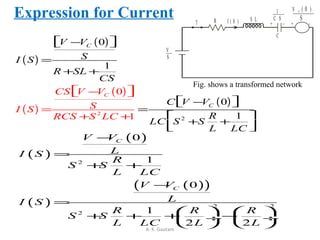
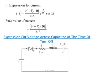
Applying KVL to figure
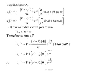
Substituting for i,
sin sin
c R L
c
t t
c
v t V v V
di
v t V iR L
dt
A d A
v t V R e t L e t
dt
δ δ
ω ω
ω ω
− −
= − −
= − −
= − − ÷
( ) ( )
( ) [ ]
( )
( )
sin cos sin
sin cos sin
sin cos sin
2
sin cos
2
t t t
c
t
c
t
c
t
c
A A
v t V R e t L e t e t
A
v t V e R t L t L t
A R
v t V e R t L t L t
L
A R
v t V e t L t
δ δ δ
δ
δ
δ
ω ω ω δ ω
ω ω
ω ω ω δ ω
ω
ω ω ω ω
ω
ω ω ω
ω
− − −
−
−
−
= − − −
= − + −
= − + −
= − + ](https://image.slidesharecdn.com/commutationtechniquesinpowerelectronics-130502025537-phpapp02/85/Commutation-techniques-in-power-electronics-12-320.jpg)
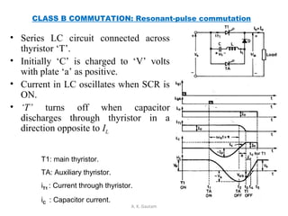
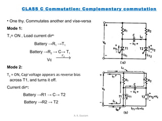
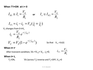
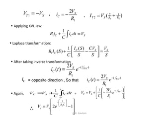
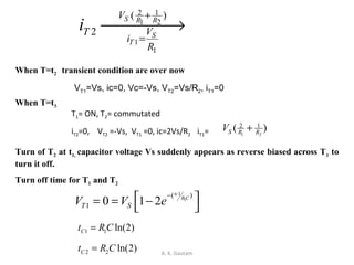
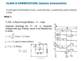
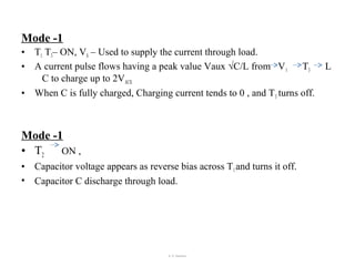


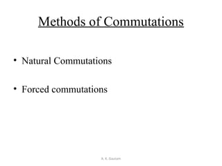
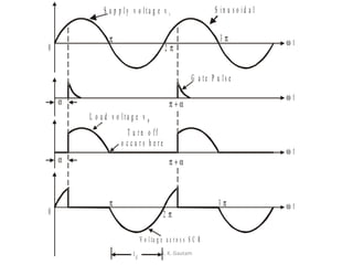
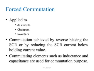
Thyristor commutation techniques can be natural or forced. Natural commutation occurs in AC circuits when the thyristor turns off as the AC voltage passes through zero. Forced commutation is used in DC circuits using methods like self, resonant pulse, complementary, and impulse commutation. Self commutation uses an underdamped LC circuit to create oscillating current that turns off the thyristor when current reaches zero. Resonant pulse commutation uses an auxiliary thyristor to discharge the capacitor and create reverse voltage across the main thyristor. Complementary commutation uses one thyristor to turn off the other in alternating fashion. Impulse commutation uses an inductor to create oscillating current for


