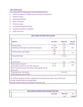
1. LINE SIZING BASIS
Line sizing will be broadly governed by following factors-
• Required capacity / available pressure drop / pumping cost
• Velocity criteria
• Flow induced forces
• Noise / Vibration
• Pressure surges
• Erosion/Corrosion/Cavitation
• Liquid accumulation / slug flow
• Static electricity
LINE SIZING CRITERIA FOR LIQUIDS
Service Line Size Max Vel Nor DP
m/s Bar/km
Pump suction < 10” 1.0
0.6(Bubble point & liquid saturated with gases) 10’ to 20” 1.25
>20" 1.5
Pump suction, sub-cooled < 10” 1.5
3.5
>10" 1.8
Pump discharge 1.5 to 3
Gravity flow 0.6 0.25
Side stream draw off </= 2" 0.6
0.6
(Provide a vertical run of 3 mtr minimum >/= 3" 0.9
from nozzle of nozzle size before reducing the size of
the line)
Cooling water sub header 2.5 to 3.5
Cooling water main header
50 ~100 mtr upstream of tank, velocity to be reduced to less than 1 m/s to limit risk
of static charge (where ever applicable)
Specific services velocity to be based on case by case.
LINE SIZING CRITERIA FOR VAPOURS AND GAS
Line Size Max Vel rv2
m/s (max)
2. Vacuum service
Press < 0.01 Bara 90
0.01 to 0.05 Bara 75
>0.05 60
Steam Saturated 20 15000
Steam Superheated 30 15000
Gas
Pressure <20 Barg Note-1 6000
Pressure 20 to 50 Barg Note-1 7500
Pressure 50 to 80 Barg Note-1 10000
Pressure > 80 Barg Note-1 15000
Note-1
it should be verified that following
velocity is not exceed
Pressure Max Vel
Barg m/s
0.1 or lower 60
Upto 1 40
Upto 5 30
>5 20
EROSIONAL SERVICES
Line Size Max Vel
m/s
Mixed phase condensate
(Vertical and horizontal lines should not be affected 10 to 20
3. by slug flow
rv 5000 to 10000 , max 15000
High velocity service
In offshore facilities piping handling gaseous and
mixed phase (gas/vapour + liq)
streams, velocity will be less than erosinal velocity Ve
Ve = C/(r^0.5) -- erosional velocity fps
r = Density lbs/ft3
C Values C
For uniform corrosion < 0.3 mm/y or corrosion
inhibitor is used 100
For uniform corrosion > 0.3 mm/y 80
Discontinues service- all cases 200
Velocity in any case for continues service should be
less than (except vacuum) 50
For SV discharge to flare
Individual header Mach no < 0.75
Flare header Mach no < 0.5
The following roughness coefficients shall be used unless stated otherwise –
Material Roughness (inches)
Carbon Steel 0.0018
Flare / Vent headers (Heavily corroded) 0.018
Stainless Steel Pipe 0.001
Glass Reinforced Epoxy Pipe 0.0001