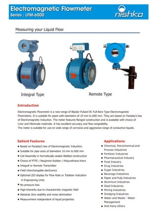
Electromagnetic flowmeters measure liquid flow using Faraday's law of electromagnetic induction. They generate a magnetic field which induces a voltage in conductive liquids proportional to flow velocity. This voltage is measured by electrodes and converted to a standardized output. Key features include a choice of wetted materials, remote or integral transmitter, accuracy from 0.5-1% of measured value, and suitability for pipes 10mm to 600mm handling corrosive or aggressive liquids. They are used in chemical, petrochemical, and other process industries.
1. Introduction
Electromagnetic Flowmeter is a new range of Bipolar Pulsed DC Full Bore Type Electromagnetic
Flowmeters. It is suitable for pipes with diameters of 10 mm to 600 mm. They are based on Faraday’s law
of Electromagnetic Induction. The meter features flanged construction and is available with choice of
Liner and Electrode materials. It has excellent accuracy and flow rangeability.
The meter is suitable for use on wide range of corrosive and aggressive range of conductive liquids.
Salient Features
Based on Faraday’s law of Electromagnetic Induction.
Suitable for pipe sizes of diameters 10 mm to 600 mm
Coil Assembly in hermetically sealed Welded construction
Choice of PTFE / Neoprene Rubber / Polyurethane liners
Integral or Remote Transmitter
Field interchangable electronics
Optional LED display for Flow Rate or Totaliser indication
in Engineering Units
No pressure loss
High linerarity due to characteristic magnetic field
Absolute Zero stability and noise elimination
Measurement independent of liquid properties
Measuring your Liquid Flow
Applications
Chemical, Petrochemical and
Process Industries
Fertilizer Industries
Pharmaceutical Industry
Food Industry
Drug Industries
Sugar Industries
Beverage Industries
Paper and Pulp Industries
Aluminum Industries
Steel Industries
Mining Industries
Dredging Industries
Water and Waste - Water
Management
And many others
Integral Type Remote Type
Electromagnetic Flowmeter
Series : LFM-6000
Electromagnetic Flowmeter
Series : LFM-6000
2. Electromagnetic Flowmeters are based on Faraday’s law of Electromagnetic Induction.
In a Electromagnetic Flowmeter, magnetic field is generated by a set of coils. As the conductive liquid
passes through the electromagnetic field, an electric voltage is induced in the liquid, which is directly
proportional to its velocity. This induced voltage is perpendicular to both the liquid flow direction and the
electromagnetic field direction. The voltage sensed by the electrodes is further processed by the transmitter
to give standardised output signal or displayed in appropriate Engineering Units on LED/LCD Display.
The flux density of the electromagnetic field in a given Flowmeter and the distance between the electrodes
are constant, therefore, the induced voltage is only a function of liquid velocity.
_
E = K.B.v.D where E : Induced voltage
K : Flow Tube Constant
B : Magnetic field velocity
_
v : Mean flow velocity
and D : Electrode Spacing
The induced voltage is not affected by the physical properties of liquid like temperature, viscosity, pressure,
density and conductivity, as long as conductivity of the measure liquid is above minimum threshold level.
For reliable measurement the pipe must be completely full of liquid.
The electromagnetic field coil assembly is excited by pulsed DC technique, which eliminates the interfering
noise and provides automatic zero correction.
Operations
Volume flow is calculated by equation :
2
Q =v.D . /4
= E.D.Therefore, Q
K.B.4
Specifications
Suitable for Pipe Sizes
Media Conductivity (Min.)
Media Pressure
Media Temperature (PTFE)
Ambient Temperature Range
Materials : Pipe
Liner
Electrode
End Connections / Flanges
Coil Housing
Transmitter
Flange / End Connection Std.
Power Supply
Power Consumption
Cable Gland Entry
Analog Output (Isolated)
Pulsed Output (Optional)
Communication Port (Optional)
Maximum Load Resistance
Response Time
Flow Velocity Range
Ingress Protection
LED Display
LCD Display
Accuracy
For Flow between 20 to 100%
For Flow between 0 to 20%
Reference Conditions
Power Supply
Ambient Temperature
Load Resistance
Repeatability
Effect of Ambient Temperature
Effect of Power Supply
Effect of Load Resistance
:
:
:
:
:
:
:
:
:
:
:
:
:
:
:
:
:
:
:
:
:
:
:
:
:
:
:
:
:
:
:
:
:
:
:
:
DN 10 to DN 600
10 µS/cm (Consult factory for 5 µS/cm)
PN 40 upto DN 80, PN 16 upto DN 200, PN 10 upto DN 600
o o
0 - 180 C with Remote transmitter
o o
0 - 120 C with Integral transmitter
o o
0 - 90 C max for other liners
o o
0 - 50 C
SS 316 (Non - magnetic )
PTFE / Neoprene / Polyurethane
SS / Hastelloy C / Ta / Ti / Pt
Carbon Steel / SS 304 / SS 316 / SS 316L
Carbon Steel / SS, Epoxy painted
Cast Aluminium (LM6) , Epoxy painted
DIN / ANSI / BS / SMS / TRI-CLAMP
110 / 240V AC + 15%, 50Hz
20 VA
1/2” NPT (F)
4-20 mA DC / 0-20 mA DC
Low Pulsed Rate Output 10 to 36000 pulses per hour
a) Output to drive directly external electromagnetic
counter of 12/24V DC @ 200 mA capacity OR
b) Open Collector Output , High Pulse Rate Output,
0.5 KHz/1 KHz/10KHz/ (Open Collector Output)
RS - 232 / RS - 485 MODBUS RTU Protocol
1000
5 seconds
0.3 to 10 m/s
IP - 65 (IP - 68 on request)
4 Digit Indication for Flow Rate and 8 Digit Indication for Totaliser
Programming from Front Keyboard for Engineering Units
16 X 2 (Two Line) Backlit LCD
+ 0.5% of measured value (calibrated) at reference conditions
+ 1% of measured value (normal)
Refer Error Diagram below
Nominal
0 0
25 + 2 C
500
+ 0.2% of span
0
Less than 0.2% per 10 C
Less than 0.1% per 10% Voltage variation
Less than 0.1% of span
3. Error Diagram :
5
4
3
2
1
0
1
2
3
4
5
20% 40% 60% 80% 100%
%ErrorofActualFlow
% Flow of Calibrated Range
-
+
Flow Rate at V = 1 m/Sec.Flow Rate Table
DN
3
m /Hr LPM LPSDN
3
m /Hr LPM LPS
Ordering Information
POWER SUPPLY
1) 240 +/- 15% V AC 50 Hz
2) 110 +/- 15% V AC 50 Hz
LINER MATERIAL
1) Teflon (PTFE)
2) Neoprene
3) Hard Rubber
4) Polyurethane
5) Any other
1) DN 10
2) DN 15
3) DN 20
4) DN 25
5) DN 32
6) DN 40
7) DN 50
8) DN 65
9) DN 80
10) DN 100
21) Any other
11) DN 125
12) DN 150
13) DN 200
14) DN 250
15) DN 300
16) DN 350
17) DN 400
18) DN 450
19) DN 500
20) DN 600
FLOW METER SIZE
ELECTRODE MATERIAL
1) Stainless Steel 316
2) Hastelloy C
3) Tantalum
4) Titanium
5) Platinium
6) Any other
FLANGE / END CONNECTIONS
STANDARDS
1) DIN PN 40
2) DIN PN 16
3) DIN PN 10
4) ANSI 300
5) ANSI 150
6) Tri-clamp
7) Any other
FLANGE / END CONNECTIONS
MATERIAL
1) Carbon Steel
2) Stainless Steel 304
3) Stainless Steel 316
4) Any other
COIL HOUSING
1) Carbon Steel
2) Stainless Steel 304
3) Stainless Steel 316
OUTPUT SIGNAL
1) 4-20 mA DC
2) 0-20 mA DC
FLOW TRANSMITTER
1) Integral without Display
2) Integral with Display
3) Remote with Display
4) Remote without Display
PULSED OUTPUT (Optional)
1) Low Pulse output
2) High Pulse output
3) Nil
COMMUNICATION PORT (Optional)
1) RS - 232
2) RS - 485
Notes : 1) Flowmeter is supplied with 2 Nos. of SS 316 Earthing Rings of 3 mm thickness.
2) Remote Flow Transmitter is supplied with 2” Pipe Mounting Kit and 10 meter each electrode signal cable and coil supply cable.
3) Installation location should be such that the Flowmeter will always remain full with liquid.
4) A minimum 5D upstream and 3D downstream straight lengths should be maintained at installation location.
where D is the pipe diameter. The Flowmeter installation location should be free of bends, elbows, tees, valves etc.
10
15
20
25
32
40
50
65
80
100
0.282
0.636
1.130
1.766
2.909
4.523
7.068
11.944
18.092
28.270
125
150
200
250
300
350
400
450
500
600
44.18
63.61
113.08
176.69
254.43
346.31
452.32
572.47
706.75
1017.72
4.711
10.601
18.846
29.447
48.247
75.386
117.791
199.100
301.546
471.166
736.198
1060.125
1884.667
2944.792
4240.500
5771.792
7538.668
9541.980
11779.169
16962.003
0.078
0.176
0.314
0.490
0.804
1.256
1.963
3.317
5.025
7.852
12.270
17.668
31.411
49.080
70.675
96.197
125.645
159.036
196.321
282.702
4. Notes : 1. Above dimensions are with ANSI 150 / DIN PN 16 flanges ( For other flanges - Consult Factory )
2. Add total 6mm for two earthing / Linear protection rings to dimension ‘D’
200
200
200
200
250
300
350
400
500
500
600
600
600
600
10, 15, 20
25, 32
40, 50
65, 80
100, 125
150
200
250
300
350
400
450
500
600
65
80
120
130
170
190
245
295
335
360
395
430
465
550
310
325
365
375
415
435
490
540
580
605
640
675
710
795
125
155
230
250
330
370
480
580
660
710
780
855
925
1090
120
150
225
245
325
365
475
575
655
705
775
850
920
1085
190
205
245
255
295
315
370
420
460
485
520
555
590
675
A B C D E FDN (mm)
Meter Dimensions in mm
Continuous efforts for product development may necessitate changes in these details without notice
Dimensional Drawing :
Integral Type
Remote Type
89
C
E
89
43
65
F
A
D
225
B
A
D
C
E
62 207
250
180
Display Housing
Junction Box
2” Pipe Mounting Kit
105
All Dimensions in mm
EI-5, Electrocnic Zone, MIDC Bhosari, Pune 411026.
Phone : 020-66305290/1, 020-27121066, 27127620, 27122304, Fax : 020-27122888
E-mail : nishko@vsnl.com Web site : www.nishko.com
NISHKO INSTRUMENTS PVT. LTD.