Download to read offline
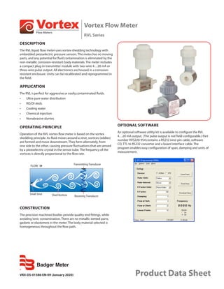


The document describes a vortex flow meter called the RVL. It uses vortex shedding technology with no moving parts to measure flow rate. It has a corrosion-resistant plastic body with integrated electronics. The meter outputs a 4-20 mA or pulse signal and can measure various clean liquids and non-abrasive slurries. It works by sensing pressure fluctuations caused by vortices formed around a central strut that are proportional to flow rate.