

Recommended
Recommended
More Related Content
What's hot
What's hot (18)
Similar to Catalog flow straighner
Similar to Catalog flow straighner (20)
Recently uploaded
Recently uploaded (20)
Catalog flow straighner
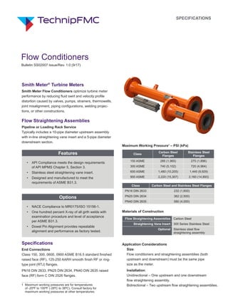
- 1. Smith Meter® Turbine Meters Smith Meter Flow Conditioners optimize turbine meter performance by reducing fluid swirl and velocity profile distortion caused by valves, pumps, strainers, thermowells, joint misalignment, piping configurations, welding projec- tions, or other constructions. Flow Straightening Assemblies Pipeline or Loading Rack Service Typically includes a 10-pipe diameter upstream assembly with in-line straightening vane insert and a 5-pipe diameter downstream section. Features • API Compliance meets the design requirements of API MPMS Chapter 5, Section 3. • Stainless steel straightening vane insert. • Designed and manufactured to meet the requirements of ASME B31.3. Options • NACE Compliance to MR0175/ISO 15156-1. • One hundred percent X-ray of all girth welds with examination procedure and level of acceptance per ASME B31.3. • Dowel Pin Alignment provides repeatable alignment and performance as factory tested. Specifications End Connections Class 150, 300, 0600, 0900 ASME B16.5 standard finished raised face (RF), 125-250 AARH smooth finish RF or ring- type joint (RTJ) flanges. PN16 DIN 2633, PN25 DIN 2634, PN40 DIN 2635 raised face (RF) form C DIN 2526 flanges. Maximum Working Pressure1 – PSI (kPa) Class Carbon Steel Flanges Stainless Steel Flanges 150 ASME 285 (1,965) 275 (1,896) 300 ASME 740 (5,102) 720 (4,964) 600 ASME 1,480 (10,205) 1,440 (9,929) 900 ASME 2,220 (15,307) 2,160 (14,893) Class Carbon Steel and Stainless Steel Flanges PN16 DIN 2633 232 (1,600) PN25 DIN 2634 362 (2,500) PN40 DIN 2635 580 (4,000) Materials of Construction Flow Straightening Assemblies Carbon Steel Straightening Vane Insert 300 Series Stainless Steel Optional Stainless steel flow straightening assembly Application Considerations Size: Flow conditioners and straightening assemblies (both upstream and downstream) must be the same pipe size as the meter. Installation: Unidirectional – One upstream and one downstream flow straightening assembly. Bidirectional – Two upstream flow straightening assemblies.1 Maximum working pressures are for temperatures of -20ºF to 100ºF (-28ºC to 38ºC). Consult factory for maximum working pressures at other temperatures. SPECIFICATIONS Flow Conditioners Bulletin SS02007 Issue/Rev. 1.0 (9/17)
- 2. 2 Bulletin SS02007 Issue/Rev. 1.0 (9/17) Pressure Drop2 2 Based on schedule 40 pipe. 3 1 cP = 1 mPa•s. To approximate pressure drop for sections with other products, multiply the chart value by the factor given below: Product Sp. Gr. Viscosity3 Factor LPG 0.51 0.2 mPa•s 0.40 Gasoline 0.73 0.7 mPa•s 0.72 Water 1.00 1.0 mPa•s 1.00 No. 6 Oil 0.95 20.0 mPa•s 2.03 *For meters of smaller size than the line in which they are installed. 1 2 3 4 5 6 7 8 9 K 2 2 Positions 1 and 2: Product Line K2 - Turbine Meter Position 3: Item 2 - Flow Straightening Assembly Position 4: Type A - Upstream Section with Straightening Vanes B - Downstream Section Position 5: Size A - 1.5" H - 8" B - 2" J - 10" C - 3" K - 12" D - 3" x 4"* L - 16" E - 4" M - 18" F - 4" x 6"* N - 20" G - 6" P - 1.5" x 2"* Catalog Code – Flow Straightening Assemblies Position 6: Pressure Class A - Class 150 ANSI H - PN16 DIN 2633 B - Class 300 ANSI J - PN25 DIN 2634 D - Class 600 ANSI K - PN40 DIN 2635 E - Class 900 ANSI Positions 7 and 8: End Connections/Tube Material 00 - RF, CS Flanges/CS Tubes A1 - RF, SS Flanges/SS Tubes B0 - RTJ, CS Flanges/CS Tubes C1 - RTJ, SS Flanges/SS Tubes D0 - RF 125-250 AARH, CS Flanges/CS Tubes E1 - RF 125-250 AARH, SS Flanges/SS Tubes Position 9: Compliance/Inspection 0 - ASME B31.3 1 - NACE Compliance* 2 - PED Compliance* 3 - X-Ray 100% Per ASME B31.3* X - Special *Designed and Manufactured to ASME B31.3
- 3. 3Bulletin SS02007 Issue/Rev. 1.0 (9/17) Dimensions – Flow Straightening Sections Upstream Assembly with Straightening Vanes Meter Downstream Assembly 5 Pipe Diameters A 10 Pipe Diameters4 3 Pipe5 Diameters 5 Pipe Diameters Locking Screw Straightening Vanes B Nominal Pipe Size A B Weight 150 Class ANSI and PN16 DIN 2633 300 Class ANSI PN25 DIN 2634 PN40 DIN 2635 600 Class ANSI Upstream Downstream Upstream Downstream Upstream Downstream 1.5" 15" (381) 7.5" (191) 30 lb (14 kg) 25 lb (11 kg) 37 lb (17 kg) 32 lb (14 kg) 45 lb (20 kg) 40 lb (18 kg) 1.5" - 2" 15" (381) 7.5" (191) 31 lb (14 kg) 25 lb (11 kg) 38 lb (17 kg) 32 lb (14 kg) C/F C/F 2" 20" (508) 10" (254) 33 lb (15 kg) 27 lb (12 kg) 40 lb (18 kg) 34 lb (15 kg) 50 lb (23 kg) 44 lb (20 kg) 3" or 3" x 4" 30" (762) 15" (381) 44 lb (20 kg) 36 lb (16 kg) 55 lb (25 kg) 47 lb (21 kg) 60 lb (27 kg) 52 lb (24 kg) 4" or 4" x 6" 40" (1,016) 20" (508) 65 lb (30 kg) 50 lb (23 kg) 85 lb (38 kg) 70 lb (32 kg) 120 lb (54 kg) 105 lb (48 kg) 6" 60" (1,524) 30" (762) 135 lb (61 kg) 95 lb (43 kg) 175 lb (79 kg) 135 lb (61 kg) 250 lb (114 kg) 210 lb (95 kg) 8" 80" (2,032) 40" (1,016) 255 lb (116 kg) 170 lb (77 kg) 310 lb (141 kg) 225 lb (102 kg) 410 lb (186 kg) 325 lb (148 kg) 10" 100" (2,540) 50" (1,270) 420 lb (191 kg) 265 lb (120 kg) 505 lb (229 kg) 340 lb (154 kg) 695 lb (316 kg) 540 lb (245 kg) 12" 120" (3,048) 60" (1,524) 655 lb (297 kg) 410 lb (186 kg) 775 lb (352 kg) 525 lb (238 kg) 950 lb (431 kg) 705 lb (320 kg) 16" 160" (4,064) 80" (2,032) 1,290 lb (586 kg) 775 lb (352 kg) 1,530 lb (695 kg) 1,015 lb (461 kg) C/F C/F 18" 180" (4,572) 90" (2,286) 1,760 lb (799 kg) 1,025 lb (465 kg) 2,090 lb (949 kg) 1,335 lb (615 kg) C/F C/F 20" 200" (5,080) 100" (2,540) 2,280 lb (1,035 kg) 1,320 lb (599 kg) C/F C/F C/F C/F Note: Dimensions – inches to the nearest tenth (millimeters to the nearest whole mm), each independently dimensioned from respective engineering drawings. 4 Increase to a minimum of 20 pipe diameters without straightening vanes and 40 pipe diameters if meter is proceeded by valves or sudden changes in flow diameter. 5 Two pipe diameters for 16" and larger. Inches (mm)
- 4. 4 Bulletin SS02007 Issue/Rev. 1.0 (9/17) Straightening Vanes Straightening vanes are thin-wall stainless steel tubes held in place by a locking screw. Material of Construction: 300 Series Stainless Steel. Catalog Code – Straightening Vanes 1 2 3 4 5 6 K 2 1 2 Positions 1 and 2: Product Line K2 - Turbine Meter Position 3: Item 1 - Flow Conditioner Position 4: Type 2 - Locking Screw Style Straightening Vane Insert 3 - Captive Flange Style Straightening Vane Insert Position 5: Size A - 1.5" J - 10" B - 2" K - 12" C - 3" L - 16" E - 4" M - 18" G - 6" N - 20" H - 8" Position 6: Flow Straightening Assembly Pipe Schedule 0 - 40 1 - 20 2 - 80 3 - 120 4 - 160 5 - XXS 6 - STD L L Set Screw Socket (Not Tapped) One set screw socket used on 1.5" through 8" nominal pipe sizes. Set Screw Socket (Not Tapped) Two set screw sockets used on 10" through 20" nominal pipe sizes. L/2L/2 L/4 Note: Dimensions – inches to the nearest tenth (millimetres to the nearest whole mm), each independently dimensioned from respec- tive engineering drawings. Nominal Pipe Size L Nominal Set Screw Diameter 1.5" 4.5" 3/8" 2" 6" 3/8" 3" 9" 3/8" 4" 12" 3/8" 6" 18" 3/8" 8" 24" 1/2" 10" 30" 1/2" 12" 32" 1/2" 16" 32" 1/2" 18" 36" 1/2" 20" 40" 1/2" Dimensions – Straightening Vanes Inches (mm)
- 5. 5Bulletin SS02007 Issue/Rev. 1.0 (9/17) 10 0.1 100 1 1000 3" 4" 200 400 600 800 1000 1 60 80 200 400 600 2000 4000 10 8 6 4 2 1.0 0.8 20 40 60 Flow - Litres per Minute Flow - GPM ∆P PSI ∆P kPa Data based on 0.73 sp. gr., 0.65 mPa•s viscosity Pressure Drop – Strate Plate
- 6. Revisions included in SS02007 Issue/Rev. 1.0 (9/17): 3" Pipe Size under dimensions revised. The specifications contained herein are subject to change without notice and any user of said specifications should verify from the manufacturer that the specifications are currently in effect. Otherwise, the manufacturer assumes no responsibility for the use of specifications which may have been changed and are no longer in effect. Contact information is subject to change. For the most current contact information, visit our website at www.fmctechnologies.com/measurementsolutions and click on the “Contact Us” link in the left-hand column. TechnipFMC.com © TechnipFMC 2017 All rights reserved. SS02007 Issue/Rev. 1.0 (9/17) TechnipFMC FMC Technologies Measurement Solutions, Inc. 500 North Sam Houston Parkway West, Suite 100 Houston, Texas 77067 USA P:+1 281.260.2190 USA Operation 1602 Wagner Avenue Erie, Pennsylvania 16510 USA P:+1 814.898.5000 Germany Operation Smith Meter GmbH Regentstrasse 1 25474 Ellerbek, Germany P:+49 4101 304.0 6