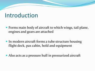
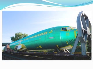
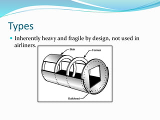
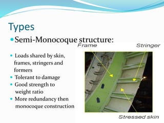
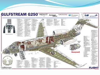
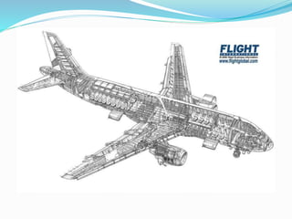
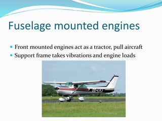
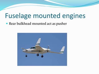
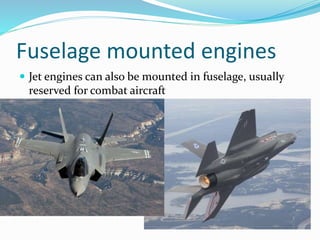
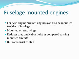
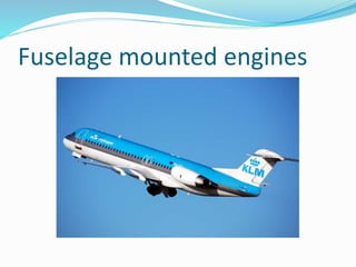
Introduction
 Forms main body of aircraft to which wings, tail plane,
engines and gears are attached
 In modern aircraft forms a tube structure housing
flight deck, pax cabin, hold and equipment
 Also acts as a pressure hull in pressurized aircraft
Types
Frame structure:
 A box frame made up of a series of vertical, horizontal,
diagonal and longitudinal tubular steel pipes
 Design produces a square profiled fuselage
 Used in old aircraft and light modern aircraft
 Frame takes up all the loads
Types
 Heavier if shape
altered
 Covered with
fabric, fiberglass,
aluminum,
Kevlar e.t.c.
Types
Types
Monocoque structure:
 Skin takes up all flight and ground loads and shape
gives structure its rigidity
 Any damage to skin directs effects its load carrying
capacity
 Complications in designing doors windows and
hatches
Types
 Inherently heavy and fragile by design, not used in
airliners.
Types
Semi-Monocoque structure:
 Loads shared by skin,
frames, stringers and
formers
 Tolerant to damage
 Good strength to
weight ratio
 More redundancy then
monocoque construction
Types
Reinforces shell structure:
 Best redundancy in shell structure
 Reinforced windows, doors and hatch attachment
points
 Longerons added for further load distribution, prevent
crack propagation
Joining methods
Riveting:
 Old process, time
consuming, more drag
Bonding:
 Using an adhesive to attach metallic parts
Joining methods
Milling:
 To remove unnecessary material
 Material retention adds rigidity
Joining methods
Etching:
 Using chemicals to remove material or create design or
shapes in billets
Pressure bulkheads
 Pressure cabin terminates at the front and rear
bulkheads
 Usually dome shaped for better pressure distribution
 In some designs floor part of pressure hull, un-
pressurised hold in this case
Cabin floors
 In modern designs are not used as bulkheads
 Series of panels attached to supporting beams of
aircraft
 Honeycomb panels
used for best
weight to strength
ratio
Blow out bungs
 Plastic blowout bungs to equalize pressure in case of
decompression
Windows
Flight deck:
 Heated for de-icing
 JAR approved for bird strikes
 Laminated like car windscreens
 Stepped nose profile used in most subsonic airliners
 Helps in:
 Aerodynamic profiling
Windows (flight deck)
 Better ground and forward visibility
 Reduction in size of screen windows
 Sheds water better
 Reduces impact force
 Reduces pressure loads
Windows (flight deck)
Stepped:
Windows (flight deck)
Exception:
Windows
Direct vision window:
 For maintaining clear vision
 Opened from inside
 Can also be used as
emergency exits
Windows
Passenger cabin windows:
 Form a part of pressure shell of fuselage
 Reinforced surrounding structure
 Windows fitted from inside and larger then apertures
 Two panes with air filled gap in between them
Windows
Doors
 Commonly plug type doors used in commercial
aircraft
 Closed from inside with locking pins engaging into
door frame
 Open by pulling back on inside and turning/sliding
sideways
Doors
Doors
Some requirements are:
 Must not be located near propellers
 Must be able to open with people surrounding it
 In emergency, external handle must be able to unlock
door
 Must open from both sides, handles to be flushed to
skin
Doors
 Must be a visual indication of doors being secured and
locked, both externally and internally. E.g. flushing
handle on outside, warning light on the crew warning
panel
 Must not jam in emergencies
 Must b a means of safe-guarding against inadvertent
operation in flight
Sealing
 Pressurization costs fuel/energy
 Every item passing through a hole is sealed
Seat mountings
 Must withstand loads e.g.
 Forward 3.0g
 Upward 9.0g
 Downward 6.0g
 Sideward 4.0g
 Seat mountings attached to crossbeams below floor
structure
Spar attachment
 The strongest part of fuselage where wings are
attached
 All flight loads converge at this point
Fuselage shapes
 Streamlined tapering design
 Suitable undercarriage/fuselage
for smaller payloads
Fuselage shapes
 Fuselages became more
cylindrical to carry more
payloads
 Engines had to be added
which added weight
penalties
 Large piston engines
give diminishing returns
Fuselage shapes
Jet engine:
 With its advent fuselage became cylindrical with rounded
nose and a tapered tail
 Advantages:
 Easy manufacturing
 Lower operating costs
Fuselage shapes
 Better power to weight ratio
 Greater cargo and passenger capacity
 Easier loading and unloading of aircraft
Fuselage shapes
Tricycle undercarriage:
 Upward tapering tail till reaching the tip of tailcone
 Top of fuselage remains unchanged
Tail bumper:
 For protection during
rotation
 Fixed or retractable
Fuselage mounted engines
 Front mounted engines act as a tractor, pull aircraft
 Support frame takes vibrations and engine loads
Fuselage mounted engines
 Rear bulkhead mounted act as pusher
Fuselage mounted engines
 Jet engines can also be mounted in fuselage, usually
reserved for combat aircraft
Fuselage mounted engines
 For twin engine aircraft, engines can also be mounted
to sides of fuselage
 Mounted on stub wings
 Reduces drag and cabin noise as compared to wing
mounted aircraft
 But early onset of stall
Fuselage mounted engines
Fuselage structures

Fuselage structures

  • 2.
    Introduction  Forms mainbody of aircraft to which wings, tail plane, engines and gears are attached  In modern aircraft forms a tube structure housing flight deck, pax cabin, hold and equipment  Also acts as a pressure hull in pressurized aircraft
  • 4.
    Types Frame structure:  Abox frame made up of a series of vertical, horizontal, diagonal and longitudinal tubular steel pipes  Design produces a square profiled fuselage  Used in old aircraft and light modern aircraft  Frame takes up all the loads
  • 5.
    Types  Heavier ifshape altered  Covered with fabric, fiberglass, aluminum, Kevlar e.t.c.
  • 6.
  • 7.
    Types Monocoque structure:  Skintakes up all flight and ground loads and shape gives structure its rigidity  Any damage to skin directs effects its load carrying capacity  Complications in designing doors windows and hatches
  • 8.
    Types  Inherently heavyand fragile by design, not used in airliners.
  • 9.
    Types Semi-Monocoque structure:  Loadsshared by skin, frames, stringers and formers  Tolerant to damage  Good strength to weight ratio  More redundancy then monocoque construction
  • 10.
    Types Reinforces shell structure: Best redundancy in shell structure  Reinforced windows, doors and hatch attachment points  Longerons added for further load distribution, prevent crack propagation
  • 13.
    Joining methods Riveting:  Oldprocess, time consuming, more drag Bonding:  Using an adhesive to attach metallic parts
  • 14.
    Joining methods Milling:  Toremove unnecessary material  Material retention adds rigidity
  • 15.
    Joining methods Etching:  Usingchemicals to remove material or create design or shapes in billets
  • 16.
    Pressure bulkheads  Pressurecabin terminates at the front and rear bulkheads  Usually dome shaped for better pressure distribution  In some designs floor part of pressure hull, un- pressurised hold in this case
  • 18.
    Cabin floors  Inmodern designs are not used as bulkheads  Series of panels attached to supporting beams of aircraft  Honeycomb panels used for best weight to strength ratio
  • 19.
    Blow out bungs Plastic blowout bungs to equalize pressure in case of decompression
  • 20.
    Windows Flight deck:  Heatedfor de-icing  JAR approved for bird strikes  Laminated like car windscreens  Stepped nose profile used in most subsonic airliners  Helps in:  Aerodynamic profiling
  • 21.
    Windows (flight deck) Better ground and forward visibility  Reduction in size of screen windows  Sheds water better  Reduces impact force  Reduces pressure loads
  • 22.
  • 23.
  • 24.
    Windows Direct vision window: For maintaining clear vision  Opened from inside  Can also be used as emergency exits
  • 25.
    Windows Passenger cabin windows: Form a part of pressure shell of fuselage  Reinforced surrounding structure  Windows fitted from inside and larger then apertures  Two panes with air filled gap in between them
  • 26.
  • 27.
    Doors  Commonly plugtype doors used in commercial aircraft  Closed from inside with locking pins engaging into door frame  Open by pulling back on inside and turning/sliding sideways
  • 28.
  • 29.
    Doors Some requirements are: Must not be located near propellers  Must be able to open with people surrounding it  In emergency, external handle must be able to unlock door  Must open from both sides, handles to be flushed to skin
  • 30.
    Doors  Must bea visual indication of doors being secured and locked, both externally and internally. E.g. flushing handle on outside, warning light on the crew warning panel  Must not jam in emergencies  Must b a means of safe-guarding against inadvertent operation in flight
  • 31.
    Sealing  Pressurization costsfuel/energy  Every item passing through a hole is sealed
  • 32.
    Seat mountings  Mustwithstand loads e.g.  Forward 3.0g  Upward 9.0g  Downward 6.0g  Sideward 4.0g  Seat mountings attached to crossbeams below floor structure
  • 33.
    Spar attachment  Thestrongest part of fuselage where wings are attached  All flight loads converge at this point
  • 34.
    Fuselage shapes  Streamlinedtapering design  Suitable undercarriage/fuselage for smaller payloads
  • 35.
    Fuselage shapes  Fuselagesbecame more cylindrical to carry more payloads  Engines had to be added which added weight penalties  Large piston engines give diminishing returns
  • 36.
    Fuselage shapes Jet engine: With its advent fuselage became cylindrical with rounded nose and a tapered tail  Advantages:  Easy manufacturing  Lower operating costs
  • 37.
    Fuselage shapes  Betterpower to weight ratio  Greater cargo and passenger capacity  Easier loading and unloading of aircraft
  • 39.
    Fuselage shapes Tricycle undercarriage: Upward tapering tail till reaching the tip of tailcone  Top of fuselage remains unchanged
  • 41.
    Tail bumper:  Forprotection during rotation  Fixed or retractable
  • 42.
    Fuselage mounted engines Front mounted engines act as a tractor, pull aircraft  Support frame takes vibrations and engine loads
  • 43.
    Fuselage mounted engines Rear bulkhead mounted act as pusher
  • 44.
    Fuselage mounted engines Jet engines can also be mounted in fuselage, usually reserved for combat aircraft
  • 45.
    Fuselage mounted engines For twin engine aircraft, engines can also be mounted to sides of fuselage  Mounted on stub wings  Reduces drag and cabin noise as compared to wing mounted aircraft  But early onset of stall
  • 46.