Downloaded 861 times
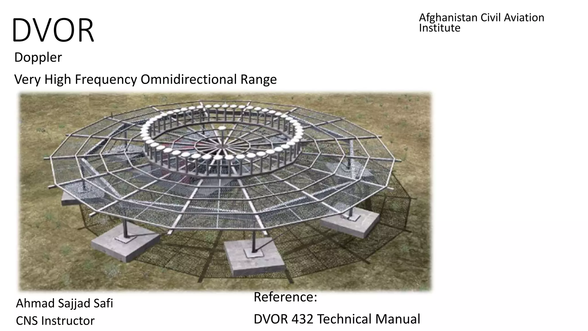
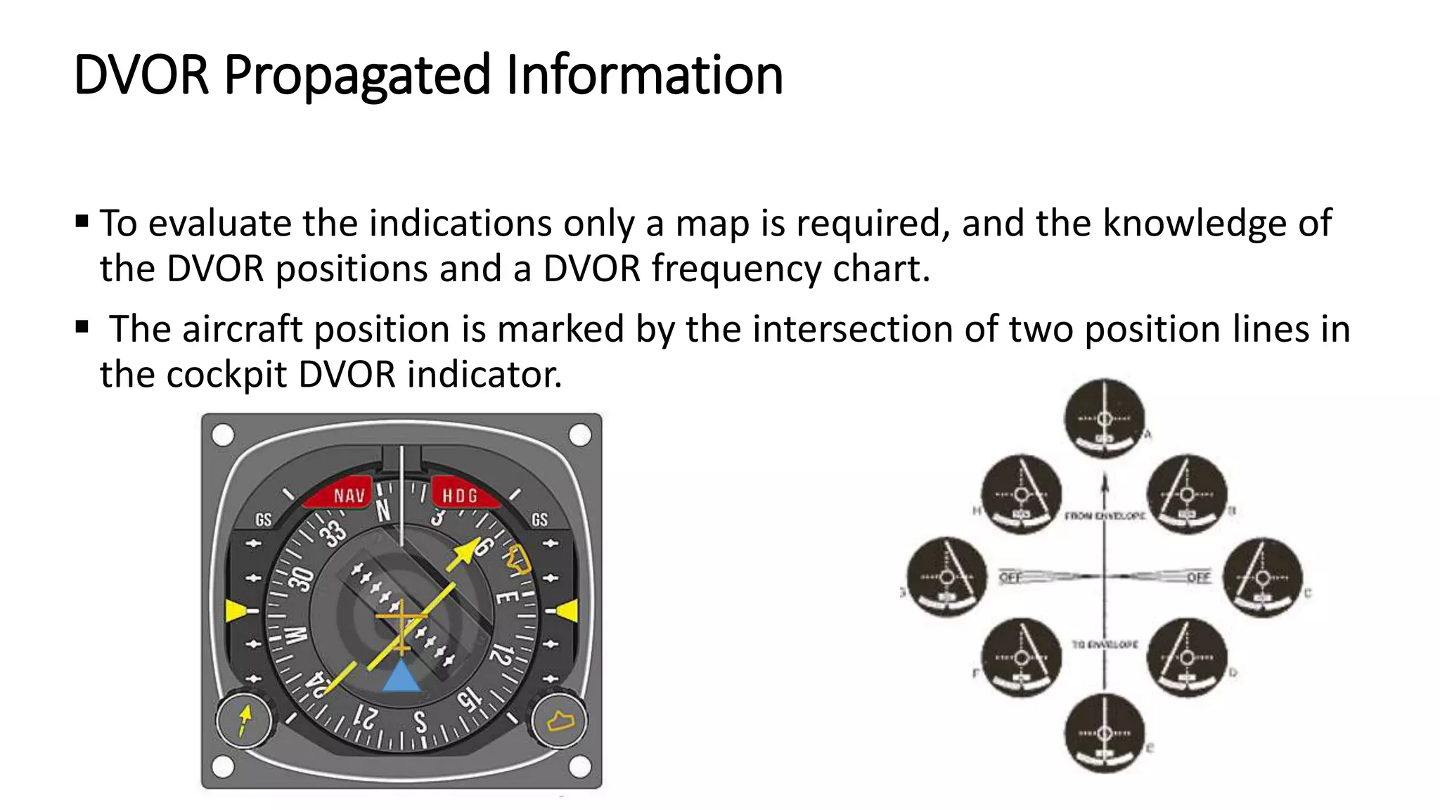
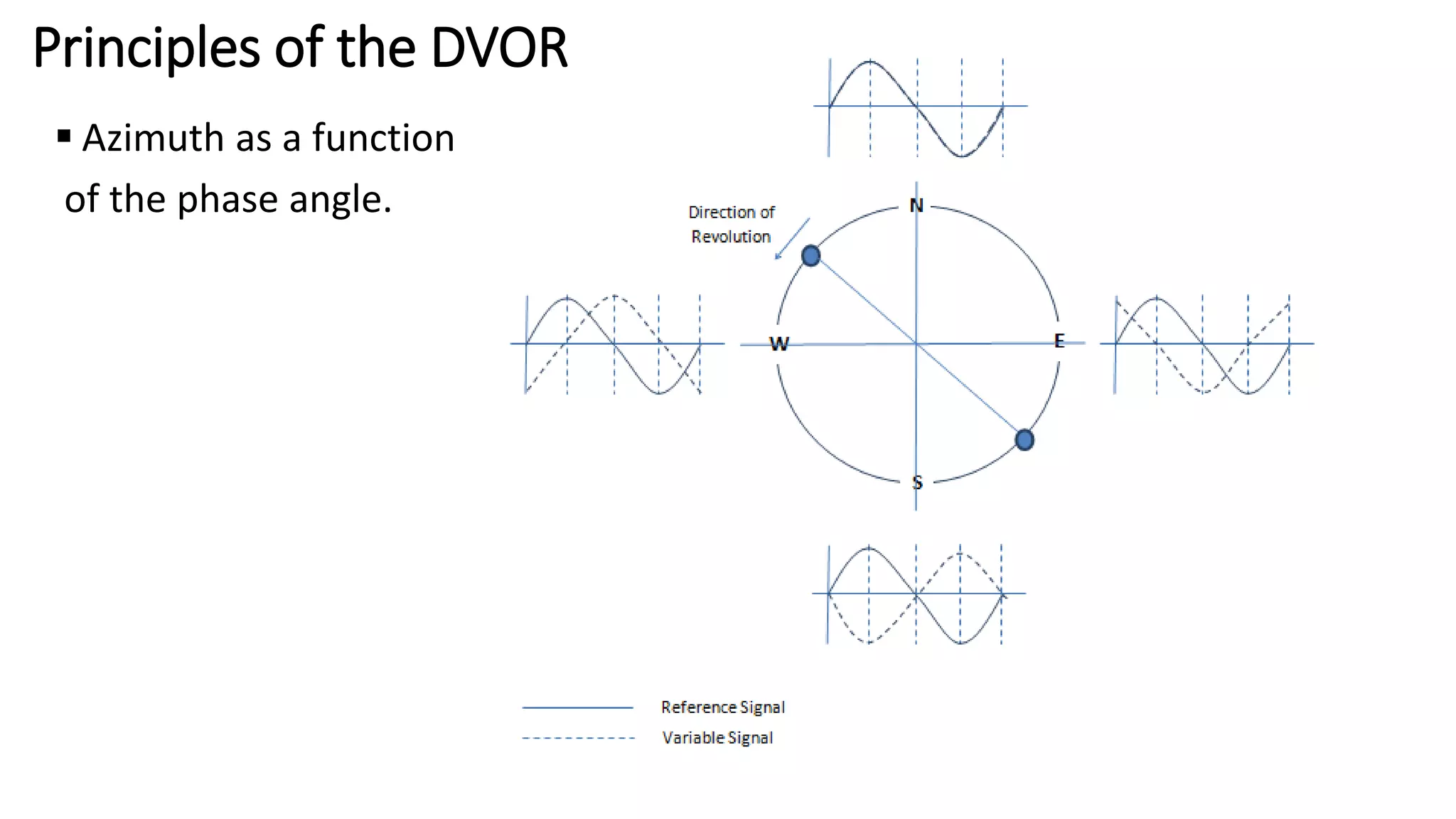
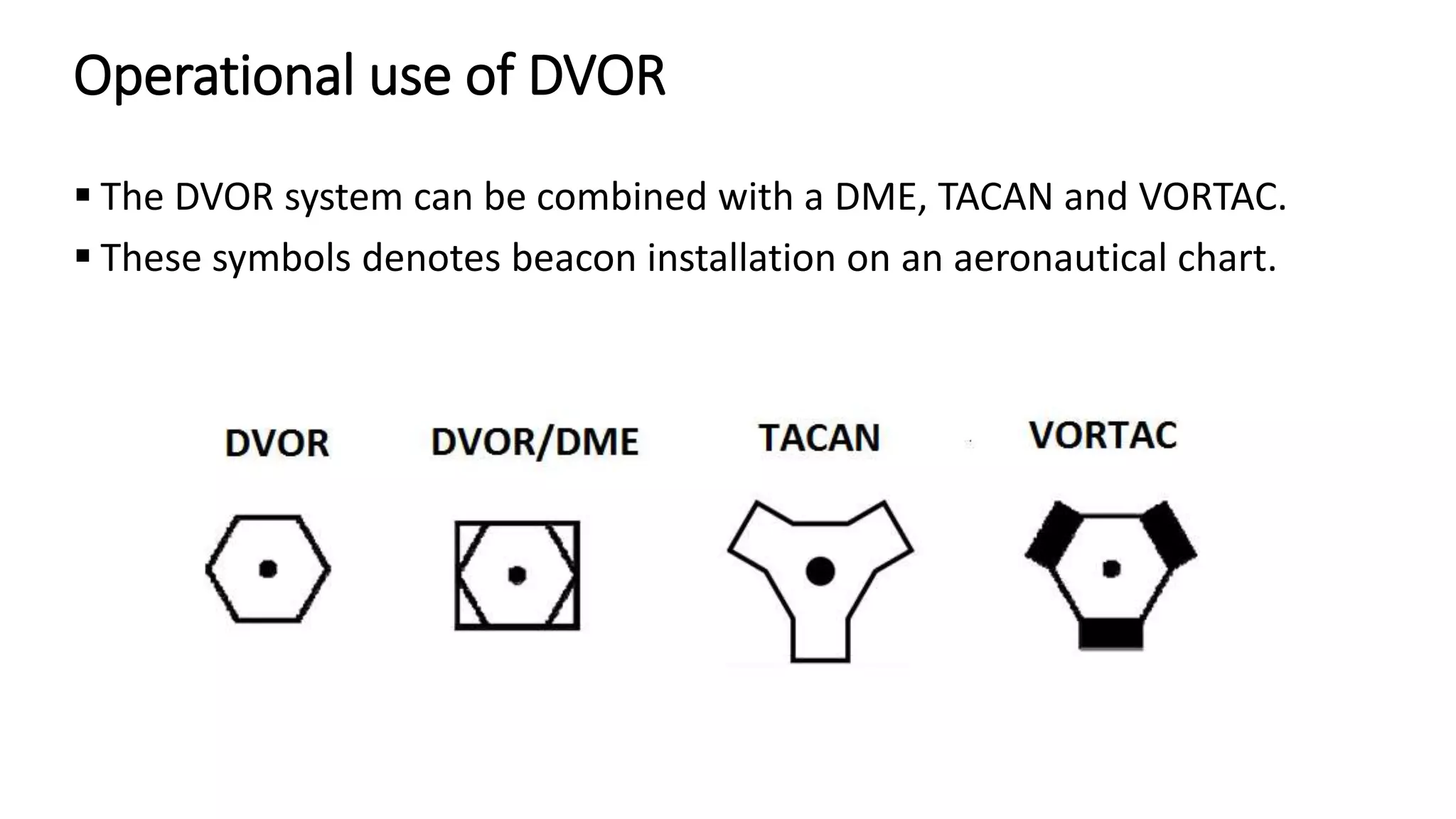
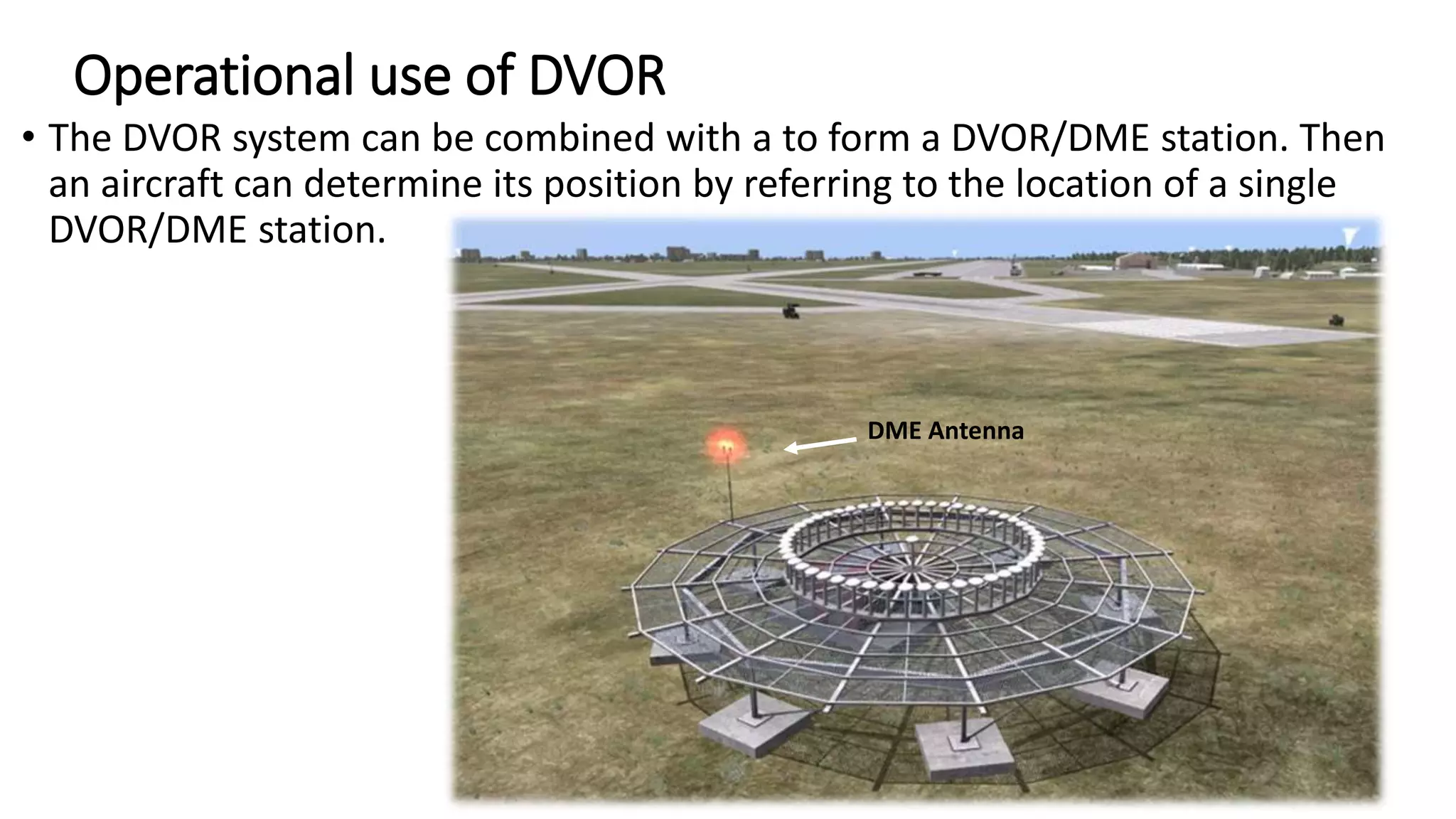
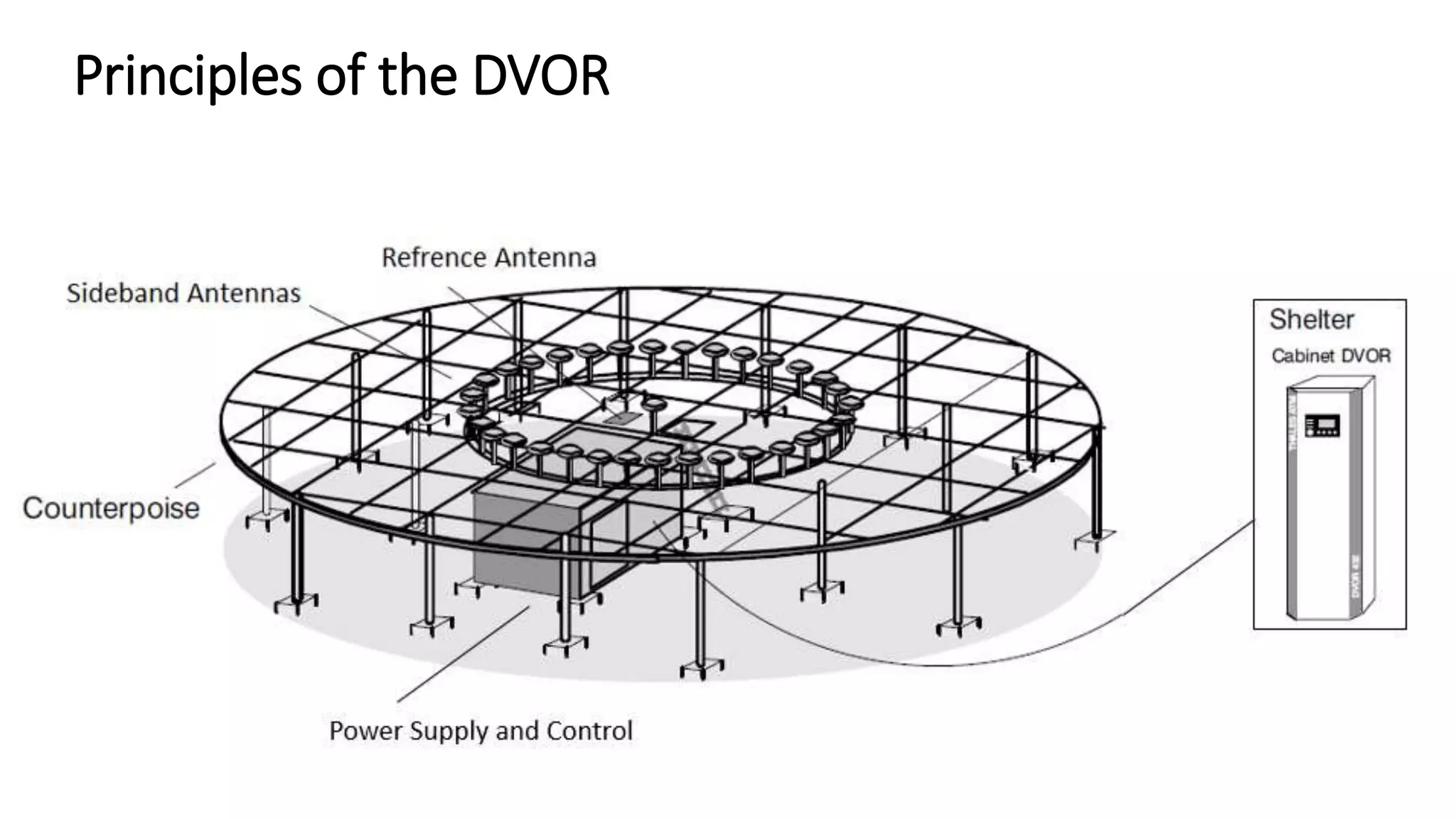

The Dvor (Doppler Very High Frequency Omnidirectional Range) is a radio navigation aid developed for short and medium-range aircraft guidance, operating within the 108-118 MHz VHF frequency range with a transmission range of 300 km. It provides pilots with critical positioning information such as azimuth, bearing, and 'from/to' indications by utilizing a phase angle difference between two 30 Hz signals. The system complies with ICAO standards, can operate as single or dual equipment, and can be integrated with other navigation systems like DME and TACAN.


![A presentation on internship from jaipur Airport [AAI]](https://cdn.slidesharecdn.com/ss_thumbnails/airportpptbyadityasept-160404162154-thumbnail.jpg?width=640&height=640&fit=bounds)


![Coded Agents – with UiPath SDK + LangGraph [Virtual Hands-on Workshop]](https://cdn.slidesharecdn.com/ss_thumbnails/codedagentsdeck-251215155422-5497c599-thumbnail.jpg?width=640&height=640&fit=bounds)


