Downloaded 180 times
![All Rights Reserved Copyright (C) Bee Technologies Inc. 2012 1
3-Phase AC Motor Model
Simplifies SPICE Behavior Model
[LTspice Model Version]
Bee Technologies Inc.](https://image.slidesharecdn.com/3-phaseacmotormodelltspice-120913232424-phpapp01/75/3-Phase-AC-Motor-Model-LTspice-1-2048.jpg)

![4) Parameters Settings
All Rights Reserved Copyright (C) Bee Technologies Inc. 2012 5
LOAD : Load current each phase of motor [Arms]
– e.g. LL = 125Arms, 140Arms, or 400Arms
LL : Phase inductance [H]
– e.g. LL = 10mH, 100mH, or 1H
RLL : Phase resistance (Phase-to-phase) [Ω]
– e.g. RLL = 10mΩ, 100mΩ, or 1Ω
KE : Back-EMF constant [V/RPM]
– e.g. KE= 0.01, 0.05, or 0.1
KT : Torque constant [Lb-in/A]
– e.g. KT= 0.1, 0.5, or 1
1 Pound Inch equals 0.11 Nm
Model Parameters:
Fig. 4 Symbol of 3-Phase Induction Motor
• From the 3-Phase Induction Motor specification, the model is characterized by setting parameters
LL, RLL, KE, KT and LOAD.](https://image.slidesharecdn.com/3-phaseacmotormodelltspice-120913232424-phpapp01/75/3-Phase-AC-Motor-Model-LTspice-5-2048.jpg)

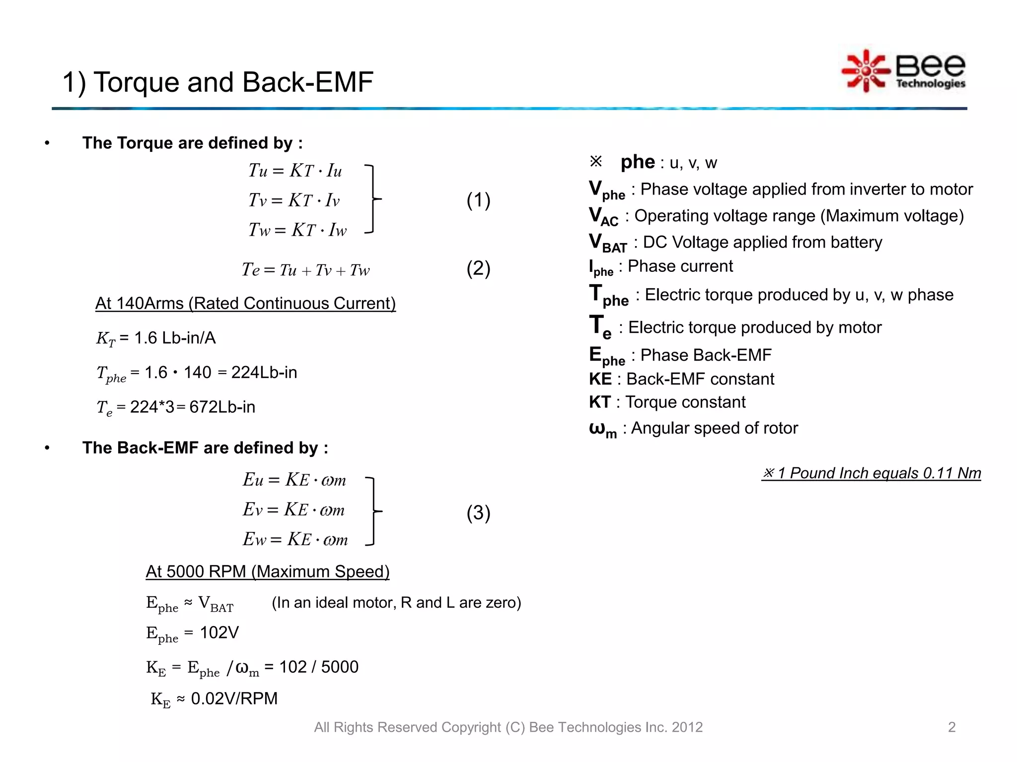
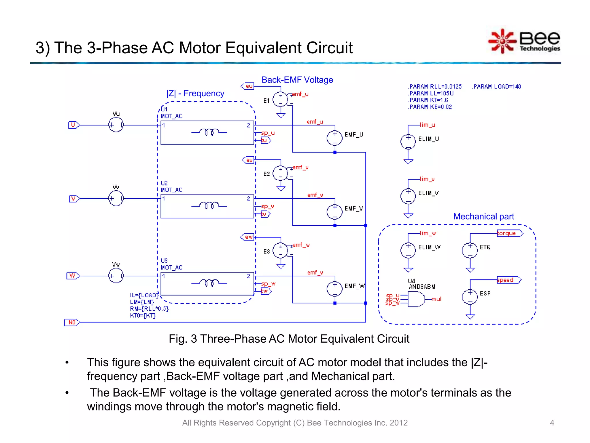
This document describes a 3-phase AC motor model for simulation in SPICE. It includes: 1) Definitions of torque and back-EMF constants based on rated current and maximum speed. 2) A simplified 3-phase AC motor model showing the relationships between phase voltages, currents, torque, back-EMF, and angular speed. 3) An equivalent circuit diagram of the motor model including impedance, back-EMF voltage, and mechanical parts.