2. 2
INTRODUCTORY OVERVIEW
Almost all coal, nuclear, geothermal, solar thermal electric and waste incineration plants, as well as many
natural gas power plants are thermal. Natural gas is frequently combusted in gas turbines as well
as boilers. The waste heat from a gas turbine can be used to raise steam, in a combined cycle plant that
improves overall efficiency. Power plants burning coal, oil, or natural gas are often referred to
collectively as fossil-fuel power plants. Some biomass-fueled thermal power plants have appeared also.
Non-nuclear thermal power plants, particularly fossil-fueled plants, which do not use cogeneration, are
sometimes referred to as conventional power plants.
Commercial electric utility power stations are most usually constructed on a very large scale and designed
for continuous operation. Electric power plants typically use three-phase or individual-phase electrical
generators to produce alternating current (AC) electric power at a frequency of 50 Hz or 60 Hz (hertz,
which is an AC sine wave per second) depending on its location in the world. Other large companies or
institutions may have their own usually smaller power plants to supply heating or electricity to their
facilities, especially if heat or steam is created anyway for other purposes. Shipboard steam-driven power
plants have been used in various large ships in the past, but these days are used most often in
large naval ships. Such shipboard power plants are general lower power capacity than full-size electric
company plants, but otherwise have many similarities except that typically the main steam turbines
mechanically turn the propulsion propellers, either through reduction gears or directly by the same shaft.
The steam power plants in such ships also provide steam to separate smaller turbines driving electric
generators to supply electricity in the ship. Shipboard steam power plants can be either conventional or
nuclear; the shipboard nuclear plants are mostly in the navy. There have been perhaps about a
dozen turbo-electric ships in which a steam-driven turbine drives an electric generator which powers
an electric motor for propulsion.
In some industrial, large institutional facilities, or other populated areas, there are combined heat and
power (CHP) plants, often called cogeneration plants, which produce both power and heat for facility
or district heating or industrial applications. AC electrical power can be stepped up to very
high voltages for long distance transmission with minimal loss of power. Steam and hot water lose energy
when piped over substantial distance, so carrying heat energy by steam or hot water is often only
worthwhile within a local area or facility, such as steam distribution for a ship or industrial facility or hot
water distribution in a local municipality.
3. 3
DEFINITION IN BRIEF
A thermal power station is a power plant in which the prime mover is steam driven. Water is heated, turns
into steam and spins a steam turbine which either drives an electrical generator or does some other work,
like ship propulsion. After it passes through the turbine, the steam is condensed in a condenser and
recycled to where it was heated; this is known as a Rankine cycle. The greatest variation in the design of
thermal power stations is due to the different fuel sources. Some prefer to use the term ³energy center´
because such facilities convert forms of heat energy into electrical energy.
The conversion from coal to electricity takes place in three stages.
Stage 1: The first conversion of energy takes place in the boiler. Coal is burnt in the boiler furnace to
produce heat. Carbon in the coal and Oxygen in the air combine to produce Carbon Dioxide and heat.
Stage 2: The second stage is the thermodynamic process.
1. The heat from combustion of the coal boils water in the boiler to produce steam. In modern power
plant, boilers produce steam at a high pressure and temperature.
2. The steam is then piped to a turbine.
3. The high pressure steam impinges and expands across a number of sets of blades in the turbine.
4. The impulse and the thrust created rotates the turbine.
5. The steam is then condensed and pumped back into the boiler to repeat the cycle.
Stage 3: In the third stage, rotation of the turbine rotates the generator rotor to produce electricity based
of Faraday¶s Principle of electromagnetic induction.
4. 4
ENVIRONMENTAL IMPACT OF THERMAL POWER STATIONS
Thermal Power Stations in India, where poor quality of coal is used, add to environmental degradation
problems through gaseous emissions, particulate matter, fly ash and bottom ash. Growth of manufacturing
industries, in public sector as well as in private sector has further aggravated the situation by deteriorating
the ambient air quality. Ash content being in abundance in Indian coal, problem of fly ash and bottom
ash disposal increase day by day. The fly ash generated in thermal power station causes many hazardous
diseases like Asthma, Tuberculosis etc.
Air pollution
Initially, perceptions of objectionable effects of air pollutants were limited to those easily detected like
odour, s oiling of surfaces and smoke stacks. Later, it was the concern over long term/chronic effects that
led to the identification of six criteria pollutants. These six criteria pollutants are sulphur di -oxide (SO2)
Carbon Mono-oxide (CO), Nitrogen oxide (NO2), Ozone (O3), suspended particulates and non-methane
hydrocarbons (NMHC) now referred to as volatile organic compounds (VOC). There is substantial
evidence linking them to health effects at high concentrations. Three of them namely O3, SO2 and NO2
are also known phytotoxicants (toxic to vegetation). In the later part Lead (Pb) was added to that list.
Nitrogen Oxide (NOx)
Most of the NOx is emitted as NO which is oxidised to NO2 in the atmosphere. All combustion
processes are sources of NOx at the high temperature generated in the combustion process. Formation of
NOX may be due to thermal NOx which is the result of oxidation of nitrogen in the air due to fuel NOx
which is due to nitrogen present in the fuel. Some of NO2 will be converted to NO3 in the presence of
02. In general, higher the combustion temperature the higher NOx is produced. Some of NOx is oxidised
to NO3 , an essential ingredient of acid precipitation and fog. In addition, NO2 absorbs visible light and
in high concentrations can contribute to a brownish discoloration of the atmosphere.
Sulphur Oxide
The combustion of sulphur containing fossil fuels, especially coal is the primary source of SOx. About
97 to 99% of SOx emitted from combustion sources is in the form of Sulphur Di -oxide which is a
criteria pollutant, the remainder is mostly SO3, which in the presence of atmospheric water is transformed
into Sulphuric Acid at higher concentrations, produce deleterious effects on the respiratory system. In
addition, SO2 is phytotoxicant.
Particulate matter
The terms particulate matter, particulate, particles are used interchangeably and all refer to finely divided
solids and liquids dispersed in the air.
5. 5
Water pollution
Water pollution refers to any change in natural waters that may impair further use of the water, caused by
the introduction of organic or inorganic substances or a change in temperature of the water.
In thermal power stations the source of water is river, lake, pond or sea where from water is
usually taken. There is possibility of water being contaminated from the source itself. Further
contamination or pollution could be added by the pollutants of thermal power plant waste as inorganic or
organic compounds.
Land degradation
The thermal power stations are generally located on the non-forest land and do not involve much
Resettlement and Rehabilitation problems. However it's effects due to stack emission etc, on flora and
fauna, wild life sanctuaries and human life etc.have to be studied for any adverse effects. One of the
serious effects of thermal power stations is land requirement for ash disposal and hazardous elements
percolation to ground water through ash disposal in ash ponds. Due to enormous quantity of ash content
in India coal, approximately 1 Acre per MW of installed thermal capacity is required for ash disposal.
According to the studies carried out by International consultants if this trend continues, by the year 2014 -
2015, 1000 sq. km of land should be required for ash disposal only.
Noise pollution
Some areas inside the plant will have noisy equipments such as crushers, belt conveyors, fans, pumps,
milling plant, compressors, boiler, turbine etc. Various measures taken to reduce the noise generation and
exposure of workers to high noise levels in the plant area will generally include:
i) Silencers of fans, compressors, steam safety valves etc.
ii) Using noise absorbent materials.
iii) Providing noise barriers for various areas.
iv) Noise proof control rooms.
v) Pro vision of green belt around the plant will further reduce noise levels.
6. 6
TECHNOLOGY UPGRADATION
Clean coal technologies
Clean coal technologies offer the potential for significant reduction in the environmental emissions when
used for power generation. These technologies may be utilized in new as well as existing plants and are
therefore, an effective way of reducing emissions in the coal fired generating units. Several of these
Systems are not only very effective in reducing SOx and NOx emissions but because of their higher
efficiencies they also emit lower amount of CO2 per unit of power produced. CCT's can be used to reduce
dependence on foreign oil and to make use of a wide variety of coal available
Blending of various grades of raw coal along with beneficiation shall ensure consistency in quality of coal
to the utility boilers. This approach assumes greater relevance in case of multiple grades of coals available
in different parts of the country and also coals of different qualities being imported by IPPs. Ministry of
Environment and Forests vide their notification dated 30th June 1998 had stipulated the use of raw or
blended or beneficiated coal with ash content not more than 34% on an annual average basis w. e. f. 1st
June 2001.
Energy extraction from coal
The two fundamental processes for extraction of energy from coal are (i) Direct Solid Combustion such as
conventional Pulverized Coal (PC) Combustion or the emerging Fluidized Bed Combustion (FBC) and
(ii) Indirect combustion through Coal Gasification followed by coal gas combustion
Fluidized Bed Combustor is a ³three-in-one device´ characterized by highly desirable features of multi-
fuel capability, pollution (SO2 and NOx) control, and energy conservation. All the four members of this
family, namely Atmospheric Fluidized Bed Combustor (AFBC), Circulating Fluidized Bed Combustor
(CFBC), Pressurized Fluidized Bed Combustor (PFBC) and Pressurized Circulating Fluidized Bed
Combustor (PCFBC) have the potential for clean power generation. Additionally, PFBC and PCFCB
systems operating in a combined cycle mode (Rankine and Braxton) have the potential for overall plant
Efficiencies of the order of 40-45% compared to 33-37% efficiencies offered by power plants based on
Conventional PC firing, AFBC and CFBC operating on a single (Rankine) cycle.
Coal gasification, at pressures up to 40 atm and suitable temperatures, results in a low calorific value (4-
7 MJ/Nm3) gas mixture of CO and H2, which can be burnt and expanded in a gas turbine for power
generation. In an Integrated Gasifier Combined Cycle (IGCC) plant, this is supplemented by steam
turbine power generation using steam generated from the gas turbine exhaust gases. Three types of coal
gasifiers are in different stages of demonstration and commercialisation in the world: Fixed Bed (Moving
Bed) Gasifier (e.g. the LURGI Dry Ash System), Fluidised Bed Gasifier (e.g. KRW system and 21
Entrained Bed Gasifier (e.g. Shell and Texaco Systems). Each of these technologies is suited to a
particular type of coal, and under specific operating conditions gives the desired quality of product coal
gas.
7. 7
Coal utilization technology
Clean coal utilization technologies
A number of technologies based on coal combustion/coal gasification/combination of coal combustion
and coal gasification aimed at environmental acceptability and high efficiency have been under
development for almost three decades.
Coal beneficiation
Coal Beneficiation has been identified as essential for Indian high ash non- caking (power grade) coals to
improve the power plant performance and reduce overall costs. Coal washeries to supply clean coal to
power plants more than 1000 km from the coal mines have been made mandatory from June 2001. Three
coal washeries were proposed at Piparwar, Bina and Kalinga. One is in operation Standard benefication
technology is available. However technology improvements are needed to increase the amount of ash
removal. Pre- combustion physical cleaning of coal to reduce sulphur is not practised, as it is not essential
at present.
Fluidised bed combustion
Fluidized bed combustion (FBC) reduces emissions of SO2 and NO2 by controlling combustion
parameters and by injecting a sorbent (such as crushed limestone) into the combustion chamber along
with the coal. Coal mixed with the limestone is fluidized on jets of air in the combustion chamber.
Sulphur released from the coal as SO2 is captured by the sorbent in the bed to form a solid calcium
compound that is removed with the ash. The resultant waste is a dry, benign solid that can be disposed of
easily or used in agricultural and construction applications. More than 90 per cent of the SO2 can be
captured this way.
At combustion temperatures of 1,400 to 1,600° F, the fluidized mixing of the fuel and sorbent
enhanced both combustion and sulphur capture. The operating temperature range is about half that of a
conventional pulverized coal boiler and below the temperature at which thermal NOx is formed. In fact,
fluidized bed NOx emissions are about 70 to 80 percent lower than those for conventional pulverized coal
boilers. Thus, fluidized bed combustors substantially reduce both SO2, NOx emissions. Also, fluidized
bed combustion has the capability of using high ash coal, whereas conventional pulverized coal units
must limit ash content in the coal to relatively low levels.
Integrated gasification combined cycle(IGCC)
The integrated coal gasification combined-cycle process has four basic steps (1) fuel gas is generated
from coal reacting with high temperature steam and an oxidant (oxygen or air) in a reducing atmosphere,
(2) the fuel gas is either passed directly to a hot gas cleanup system to remove particulates, sulphur, and
nitrogen compounds or first cooled to produce steam and then cleaned, (3) the clean fuel gas is combusted
in a gas turbine generator to produce electricity and (4) the residual heat in the hot exhaust gas from the
gas turbine is recovered in a heat recovery steam generator, and the steam is used to produce additional
electricity in a steam turbine generator.
8. 8
Integrated gasification combined-cycle (IGCC) systems are among the cleanest and most efficient of the
emerging clean coal technologies. Sulphur, nitrogen compounds, and particulates are removed before the
fuel is burned in the gas turbine, that is, before combustion air is added. For this reason, there is a much
lower volume of gas to be treated than in a post combustion scrubber. The chemical composition of the
gas requires that the gas stream must be cleaned to a high degree, not only to achieve low emissions, but
to protect downstream components, such as the gas turbine, from erosion of corrosion.
In a coal gasifier, the sulphur in the coal is released in the form of hydrogen sulphide (H2S) rather than
as SO2, which is the case in conventional pulverized coal combustion. In some IGCC systems, much of
the sulphur containing gas is captured by a sorbent injected into the gasifier. Others use existing proven
commercial hydrogen sulphide removal processes, which remove up to 99% of the sulphur, but require
the fuel to be cooled, which is an efficiency penalty Therefore; hot gas cleanup systems are now being
demonstrated. In these cleanup systems, the hot coal gas is passed through a bed of metal oxide particles,
such as supported zinc oxides. Zinc oxide can absorb sulphur contaminants at temperatures in excess of
1,000° F and the compound can be regenerated and reused with little loss of effectiveness. Produced
during the regeneration stage are salable sulphur, sulphuric acid, or sulphur-containing solid waste, which
may be used to produce useful by-products, such as gypsum .The technique is capable of removing more
than 99.9 per cent of the sulphur in the gas stream. With hot gas clean up, IGCC systems have the
potential for efficiencies of over 50 per cent.
Fig. Coal to Electricity Basics
9. 9
Proper Site Selection for Thermal Power plants
Selecting a proper site for a thermal power plant is vital for its long term efficiency and a lot many factors
come into play when deciding where to install the plant. Of course it may not be possible to get
everything which is desirable at a single place but still the location should contain an optimum mix of the
requirements for the settings to be feasible for long term economic justification of the plant.
The following factors must be considered while selecting a site for proposed thermal power plant.
1. The site must be near a stream or river, since plenty of water would be needed for purposes of
cooling. The presence or absence of such a source of water influences the design of the power
plant.
2. If the plant is to be erected near a town or city , the cost of land required should be reasonably
low .
3. The land should be level, as otherwise huge expenditure might be incurred for preparing the land
for the construction of the power plant.
4. The land should be neither rocky nor marshy, a pile foundation might be necessary. This
enhances the capital cost.
5. If the site is far from coal mines, the cost of transportation of enormous quantities of the fuel
might be prohibitively high.
6. Adequate facilities must be available at the site for storing large quantities of coal and ash.
7. The site must be such that future expansion of the power plant does not encounter any problem.
8. Skilled labour must be available locally
9. The site must be such that the erection of high chimney for discharging the flue gases to the
atmosphere does not pose any problem.
PULVERISED COAL FIRING SYSTEM
1. In the pulverized coal firing system the coal is reduced to fine powder with the help of grinding
mill and then introduced in the combustion chamber with the help of primary hot air.
2. The primary air also helps to dry the air before entering the combustion chamber.
3. Secondary air required to complete the combustion process is supplied separately to the
combustion chamber.
4. The resulting turbulence in the combustion chamber helps in proper mixing of fuel and air and
good combustion.
10. 10
PULVERISED COAL
1. Coal is pulverized (powdered) to increase its surface area and thereby permit rapid combustion
2. The pulverized coal is obtained by grinding the raw coal in pulverizing mills. Various types of
pulverizing mills are:
y Ball Mill
y Ball and Race mill
y Hammer mill
y Bowl mill
11. 11
3. Essential functions of pulverizing mills are:
y Drying of coal
y Grinding
y Separation of particles of a desired size
ADVANTAGES OF PULVERIZED COAL FIRING SYSTEM
1. Any grade of coal can be used because coal is powdered before use.
2. Rate of feed of fuel can easily be regulated- better fuel economy.
3. Since there is almost complete combustion of fuel, there is increased rate of evaporation, thus
boiler efficiency is increased.
4. Greater capacity to meet peak load.
5. Practically no ash handling problem.
6. This system works successfully in combination of gas and oil.
DISADVANTAGES OF PULVERISED COAL FIRING SYSTEM
1. High capital cost.
2. Possibility of explosion is more because pulverized coal burns like gas.
3. Maintenance of furnace brick work is costly because of high temperatures.
4. Separate coal preparation plant is necessary.
5. Periodic maintenance of pulverized coal dispensing system is needed.
13. 13
COAL HANDLING PLANT
Coal is used as a main fuel in thermal power station. As the consumption of coal is huge, the
layout of a coal handling plant should be simple, reliable and low maintenance.
Coal is brought to power station by three means of coal transportation i.e. roadways, railways
and ropeways.
Coal brought by railways is unloaded with the help of wagon tippler in a coal hopper. The
movement of wagons is controlled by automatic in-haul and out-hauls beetle chargers. This coal
is then feeded to coal conveyor belt through vibrating feeder. These feeders are of electro-
magnetic type and controls the rate of feeding required for bunkering. By the various
combinations of conveyor belts, coal is conveyed to the surge hopper of a crusher house. Before
the coal comes to the crusher house, the ferrous material which comes along with the coal is
taken out with the help of suspended and rotating type magnetic separators. Non-ferrous
materials like stones.shells, wood etc. are removed manually. From surge hopper, coal is fed to
the coal crusher through mechanical feeder. Here coal is crushed to the size of 20-25 mm.
This sized coal is then sent to coal bunkers through various belts and finally coal trippers and
stored for further processing of coal for combustion in boiler furnace. This cycle is known as
bunkering cycle. If bunkers are full or coal is not required due any maintenance. on units, then
coal is diverted to the stack yard with the help of stacking conveyor belts. This cycle is known as
stacking cycle. If coal is not available from any means of coal transportation and coal is urgently
required for the unit, then the stacked coal is diverted to the bunkers with the help of reclaiming
belts.
ASH HANDLING PLANT
y Large power plants produce a huge quantity of ash, sometimes as much as 10 to 20% of the coal burnt per
day. Therefore, mechanical devices are used for effective collection and disposal of ash.
y Ash handling includes:
‡ Removal of ash from furnace
‡ Loading to conveyors and delivery to fill or dump from where it can be disposed
off
ASH HANDLING EQUIPMENT
Good Ash handling equipment should have following characteristics:
y It should have enough capacity to cope with the volume of ash that may be produced in a station.
y It should be able to handle large clinkers, boiler refuse, soot etc., with little attention from workers.
y It should be able to handle hot and wet ash effectively and with good speed.
14. 14
y It should be possible to minimize the corrosive or abrasive action of ash.
y Operation of the plant should be easy, economical, simple and noiseless.
y It should be able to operate effectively under all variable load conditions.
y It should also remove fly ash and smoke to control air pollution
The commonly used ash handling equipment for ash handling in large and medium size plant may be:
1. Bucket elevator
2. Bucket Conveyer
3. Belt Conveyer
4. Trollies and rail cars
5. Hydraulic Sluicing equipment
ASH COLLECTION AND TRANSPORTATION
16. 16
BOILER
Boiler is a device to generate steam for power generation. Basically in thermal power stations water tube
boilers are used.
Water Tube Boilers:
A water tube boiler is a type of boiler in which water circulates in tubes heated externally by
the fire. Water tube boilers are used for high-pressure boilers. Fuel is burned inside the furnace,
creating hot gas which heats water in the steam-generating tubes. In smaller boilers, additional
generating tubes are separate in the furnace, while larger utility boilers rely on the water-filled
tubes that make up the walls of the furnace to generate steam.
The heated water then rises into the steam drum. Here, saturated steam is drawn off the top of the
drum. In some services, the steam will reenter the furnace through a superheater to become
superheated. Superheated steam is used to drive turbines. Since water droplets can severely
damage turbine blades, steam is superheated to 730 °F (388 °C) or higher to ensure that there is
no water entrained in the steam.
Water Tube Boilers have following advantages:
y High pressure can be obtained, about 140 Kg/cm2
y Large heating surface can be obtained by use of large number of tubes- therefore steam
can be generated easily
y Efficiency is higher because of high velocity of water in tubes which improves heat
transfer.
Water tube boilers can further be classified as :
y Horizontal Straight Tube Boilers
y Bent Tube Boilers
y Cyclone fired Boilers
17. 17
Fig. Water Tube Boilers
Cool water at the bottom of the steam drum returns to the feed water drum via large-bore
'downcomer tubes', where it pre-heats the feed water supply. (In 'large utility boilers', the
feedwater is supplied to the steam drum and the downcomers supply water to the bottom of the
waterwalls). To increase economy of the boiler, exhaust gases are also used to pre-heat the air
blown into the furnace and warm the feed water supply. Such water tube boilers in thermal
power station are also called steam generating units.
The older fire-tube boiler design ± in which the water surrounds the heat source and the gases
from combustion pass through tubes through the water space ± is a much weaker structure and is
rarely used for pressures above 350 psi (2.4 MPa). A significant advantage of the water tube
boiler is that there is less chance of a catastrophic failure: there is not a large volume of water in
the boiler nor are there large mechanical elements subject to failure.
Disadvantage of fire tube boilers is that they contain more water in the drum and if the flue gas circulation
is poor, they can not quickly meet the steam demand. For the same output, the outer shell of fire tube
boiler is much larger than the shell of a water tube boiler.
18. 18
Fig. Fire Tube Boiler
Design Variation:
D-type boiler: The 'D-type' is the most common type of small- to medium-sized boilers. It
consists of a large steam drum vertically connected to a smaller water drum (a.k.a. "mud drum")
via multiple steam-generating tubes. These are surrounded by walls made up of larger water-
filled tubes, which make up the furnace.
Low Water Content: The 'Low Water Content' boiler has a lower and upper header connected by
water tubes that are directly impinged upon from the burner. This is a "furnace-less" boiler that
can generate steam and react to load changes quickly.
Babcock and Wilcox boiler: Designed by the American firm of Babcock and Wilcox, this type has
a single drum, with feed water drawn from the bottom of the drum into a header that supplies
inclined water-tubes. The water tubes supply steam back into the top of the drum. Furnaces are
located below the tubes and drum.
This type of boiler was used by the Royal Navy's Leander class frigates. The Y160 variant used
on the Batch 3 Leanders (eg HMS Jupiter) also incorporated steam atomisation equipment on the
fuel supply so that the diesel fuel entering the boilers via the three main burners was atomised
into a fine spray for better flame efficiency. The superheat temperature of the Y160 was
controlled manually by the Boiler Room Petty Officer of the Watch between 750o
F and 850o
F
and the steam supplied to the main turbines was at a pressure of 550 psi.
19. 19
Fig. Babcock & Wilcox Boiler
Stirling boiler: The Stirling boiler has near-vertical, almost-straight watertubes that zig-zag
between a number of steam and water drums. Usually there are three banks of tubes in a "four
drum" layout, but certain applications use variations designed with a different number of drums
and banks.
They are mainly used as stationary boilers, owing to their large size, although the large grate area
does also encourage their ability to burn a wide range of fuels. Originally coal-fired in power
stations, they also became widespread in industries that produced combustible waste and
required process steam. Paper pulp mills could burn waste bark, sugar refineries their bagasse
waste.
Yarrow: Named after its designers, Glasgow-based Yarrow Shipbuilders, this type has three
drums in a delta formation connected by water tubes. The drums are linked by straight water
tubes, allowing easy tube-cleaning. This does however mean that the tubes enter the drums at
varying angles, a more difficult joint to caulk. Outside the firebox, a pair of 'cold-leg' pipes
between each drum act as 'downcomers'.
20. 20
Due to its three drums, the Yarrow boiler has a greater water capacity. Hence, this type is usually
used in older marine boiler applications. Its compact size made it attractive for use in
transportable power generation units during World War II. In order to make it transportable, the
boiler and its auxiliary equipment (fuel oil heating, pumping units, fans etc.), turbines, and
condensers were mounted on wagons to be transported by rail.
Superheater:
A superheater is a device used to convert saturated steam or wet steam into dry steam used
for power generation or processes. There are three types of superheaters namely: radiant,
convection, and separately fired. A superheater can vary in size from a few tens of feet to several
hundred feet (a few meters or some hundred meters).A radiant superheater is placed directly in
the combustion chamber.A convection superheater is located in the path of the hot gases.
Fig. General arrangement of a superheater installation in a steam locomotive.
Thermal power plants can have a superheater and/or reheater section in the steam generating
furnace. Nuclear-powered steam plants do not have such sections but produce steam at
essentially saturated conditions. In a coal fired plant, after the steam is conditioned by the drying
equipment inside the steam drum, it is piped from the upper drum area into tubes inside an area
of the furnace known as the superheater, which has an elaborate set up of tubing where the steam
vapor picks up more energy from hot flue gases outside the tubing and its temperature is now
superheated above the saturation temperature. The superheated steam is then piped through the
main steam lines to the valves before the high pressure turbine.
21. 21
Reheater:
Power plant furnaces may have a reheater section containing tubes heated by hot flue gases
outside the tubes. Exhaust steam from the high pressure turbine is rerouted to go inside the
reheater tubes to pickup more energy to go drive intermediate or lower pressure turbines. This is
what is called as thermal power.
Fuel Preparation system:
In coal-fired power stations, the raw feed coal from the coal storage area is first crushed into
small pieces and then conveyed to the coal feed hoppers at the boilers. The coal is next
pulverized into a very fine powder. The pulverizers may be ball mills, rotating drum grinders, or
other types of grinders.
Some power stations burn fuel oil rather than coal. The oil must kept warm (above its pour point)
in the fuel oil storage tanks to prevent the oil from congealing and becoming unpumpable. The
oil is usually heated to about 100 °C before being pumped through the furnace fuel oil spray
nozzles.
Boilers in some power stations use processed natural gas as their main fuel. Other power stations
may use processed natural gas as auxiliary fuel in the event that their main fuel supply (coal or
oil) is interrupted. In such cases, separate gas burners are provided on the boiler furnaces.
Steam turbines and electric generators:
It is in the steam turbines that conversion of heat energy in to mechanical energy takes place.
There are two types of steam turbines:
y Impulse Turbine
y Reaction turbine
In an impulse turbine, there are a number of nozzles and when steam is passed through this
nozzles, it expands and its velocity increases. The potential energy of steam also transform in to
kinetic energy, in addition to the internal heat. When the steam issuing forth from the nozzles
passes over the fixed and movable blades of the turbine, the kinetic energy and heat gets
transformed in to mechanical energy, resulting in the rotation of the turbine. The alternator
coupled to the turbine further converts mechanical energy in to electrical energy.
A reaction turbine also functions in a similar fashion. But there is one basic difference and that is
there are no nozzles provided in a reaction turbine. The superheated, dry steam under pressure is
directly passed over fixed and movable blades.
22. 22
Although a steam engine can also function as a prime mover for the electric generator, it is
common practice to employ steam turbines in preference to steam engines, in modern thermal
power plant.
23. 23
A steam turbine can run at very high speeds and its thermodynamic efficiency is quite high. It is usual to
couple non-salient pole rotor alternators to steam turbines, since such alternators also can run at very high
speeds.
Steam turbines can attain very high rotational speeds of the order of 30,000 r.p.m. In order to reduce the
speed to much lower levels, as demanded by practical considerations, either velocity compounding or
pressure compounding mechanisms are incorporated. Sometimes velocity pressure compounding- a
combination of two is also adopted.
`Generator:
The generator consists of rotor encased in a casing with windings. The rotor is also having winding fixed
on the rotor slots, which is connected to an excitation system in different ways. The stator is also provided
with windings. The generator rotor is coupled to the Turbine rotor.
The generator rotor is either air cooled or hydrogen cooled. The stator coils are cooled by air and in large
capacity generators by De-mineralised water.
24. 24
AIR AND DRAFT SYSTEM
OBJECTIVES:
y The air we need for combustion in furnace and flue gas that we must evacuate.
y Transport and dry the pulverized coal.
y Sealing of bearing from coal/ Dust.
Draft System:
Draft means the difference between the atmospheric pressure and pressure existing in the furnace.
y Natural draft obtained by tall chimney.
y Induced draft by- ID fans.
y Forced Draft by- FD fans.
y Balanced draft by- ID and FD fans.
Generally in Power plants Balanced draft system is used.
FANS IN POWER PLANT:
y Forced Draft fan
y Induced draft fan
y Primary Air fan
y Seal Air fan
y Scanner Air fan
The basic information needed to select a fan are:
y Air or Gas flow-Kg/Hr
y Density(function of temperature and pressure)
y System resistance (Losses)
AIR PREHEATERS
OBJECTIVE:
To raise the temperature of primary and secondary air by utilizing heat from flue gases at low
temperature.
The air which is pumped in to the combustion chamber i.e. furnace or fire space of the boiler, is preheated
so as to improve the thermal efficiency of the plant. These are located at the path of the flue gases, in
between the exit of the boiler and the entrance of the chimney.
25. 25
Cold air from outside is pumped in to the preheaters . Here the air comes in to contact with the flue gases,
and a large part of the heat still left in the flue gases gets transferred to the cold air, with the result that air
gets heated. The hot air is then supplied to the furnace.
Advantages of preheaters:
y Increase the boiler efficiency
y Stability of combustion is improved by the use of hot air
y Permitting to burn poor quality coal
Fig. Air Preheater(tubular type)
26. 26
ELECTROSTATIC PRECIPITATOR (ESP)
OBJECTIVE:
To remove fly ash from the flue gases
Collection Efficiency:
Precipitator performance is very sensitive due to two particulate properties: 1) Resistivity; and 2)
Particle size distribution. These properties can be determined economically and accurately in the
laboratory. A widely taught concept to calculate the collection efficiency is the Deutsch model,
which assumes infinite remixing of the particles perpendicular to the gas stream.
Resistivity can be determined as a function of temperature in accordance with IEEE Standard
548. This test is conducted in an air environment containing a specified moisture concentration.
The test is run as a function of ascending or descending temperature or both. Data are acquired
using an average ash layer electric field of 4 kV/cm. Since relatively low applied voltage is used
and no sulfuric acid vapor is present in the environment, the values obtained indicate the
maximum ash resistivity.
Usually the descending temperature test is suggested when no unusual circumstances are
involved. Before the test, the ash is thermally equilibrated in dry air at 454 °C (850°F) for about
14 hours. It is believed that this procedure anneals the ash and restores the surface to pre-
collection condition.
If there is a concern about the effect of combustibles, the residual effect of a conditioning agent
other than sulfuric acid vapor, or the effect of some other agent that inhibits the reaction of the
ash with water vapor, the combination of the ascending and descending test mode is
recommended. The thermal treatment that occurs between the two test modes is capable of
eliminating the foregoing effects. These results in ascending and descending temperature
resistivity curves that show a hysteresis related to the presence and removal of some effect such
as a significant level of combustibles.
With particles of high resistivity (cement dust for example) Sulfur trioxide is sometimes injected
into a flue gas stream to lower the resistivity of the particles in order to improve the collection
efficiency of the electrostatic precipitator.
Fig. Side view of ESP
27. 27
PRINCIPLE OF OPERATION OF ESP
The flue gas laden with fly ash is sent through ducts having negatively charged plates which give the
particles a negative charge. The particles are then routed past positively charged plates, or grounded
plates, which attract the now negatively-charged ash particles. The particles stick to the positive plates
until they are collected by periodically.
Fig. ESP FUNCTION
ECONOMISER
The Thermal efficiency of a steam power plant can be improved by the use of Economiser. The main
function of the economizer is to extract as much of heat as possible from the flue gases and utilize this
heat for the purpose of preheating of boiler feed water. In practice, the water that is supplied to the boiler
for raising steam is preheated at several stages before it is delivered to the boiler. This not only increases
Thermal efficiency, but also brings about economy in the use of fuel.
The Economiser is located in the path of the flue gases. It mainly consists of an arrangement of vertical
tubes through which the feed water is circulated. The flue gases are made to surround these tubes, The
feed water absorbs much of the heat of the flue gases and becomes quiet hot. It is then supplied to the
boiler.
The inherent demerit of this technique is that, since the tubes are surrounded by flue gases, soots get
deposited on the outer walls of the tubes. It is necessary to remove this soot periodically; as otherwise, the
collected soot prevents the water from absorbing the heat of the flue gases. In practice MECHANICAL
SCARPERS are provide for removal of the soot.
28. 28
Fig. Economiser
CONDENSER
Its main function is to condense the low pressure wet steam coming out of the turbines in to the water so
that this water can be used again as feed water.
In practice the low pressure wet steam coming out of the turbine is passed through the condenser.
Here cold water is continuously circulated. The low pressure wet steam gives out whatever heat it has to
the circulating cold water and condenses in to water. The condensate is extracted and preheated to a
sufficiently to a high temperature and hot water is supplied back to the boiler as feed water.
There are two types of condensers in practice:
y Surface Condenser
y Jet condenser/ Contact Condenser
In a contact condenser, the gas comes into contact with cold liquid. In a surface condenser, the
gas contacts a cooled surface in which cooled liquid or gas is circulated, such as the outside of
the tube. Removal efficiencies of condensers typically range from 50 percent to more than 95
percent, depending on design and applications.
30. 30
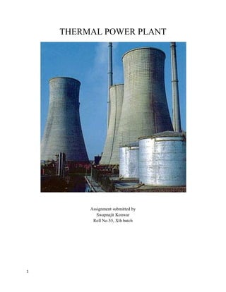
.
A cooling tower is a huge structure built of either wood or concrete. It is either rectangular or hyperbolic.
There are two types of cooling tower:
y Open(Direct) cooling towers
y Closed(Indirect) cooling towers
Open cooling towers:
Open cooling towers expose the condenser water coming from the chiller plant directly to the atmosphere.
This warm water is sprayed over a fill in the cooling tower to increase the contact area, and air passes
through the fill. Most of the heat is removed by evaporation. The cooled water remaining after
evaporation drops into the collection basin and is returned to the chiller¶s condenser.
Closed cooling towers:
A closed cooling tower circulates warm water from the chiller plant through tubes located in the tower. In
a closed tower, the cooling water does not come in contact with the outside air. Water that circulates only
within the cooling tower is sprayed over the tubes and a fan blows air across the tubes. This cools the
condenser water within the tubes, which is then recirculated to the chiller plant.
32. 32
Key components of cooling tower:
1. Water Distribution:
Hot water from the chilled-water system is delivered to the top of the cooling tower by the condenser
pump through distribution piping. In an open tower, the hot water is sprayed through nozzles onto the
heat transfer medium (fill) inside the cooling tower. Some towers feed the nozzles through pressurized
piping; others use a water-distribution basin and feed the nozzles by gravity. In a closed-loop tower, the
water from the condenser loop runs through tubes in the tower and is not exposed to the outside air. Water
for cooling the tubes circulates only in the tower.
In the open tower, a cold-water collection basin at the base of the tower gathers cool water after it has
passed through the heat transfer medium. The cool water is pumped back to the condenser to complete the
cooling-water loop. In the closed tower, the condenser water cools as it moves through the piping in the
tower and returns to the chiller plant.
2. Heat Transfer Medium(Fill):
Cooling towers use evaporation to release waste heat from an HVAC system. In an open tower, hot water
from the condenser is slowed down and spread out over the fill. Some of the hot water is evaporated in
the fill area, or over the closed-circuit tubes, which cools the water. Cooling tower fill is typically
arranged in packs of thin corrugated plastic sheets or as splash bars supported in a grid pattern.
3. Air Flow:
Large volumes of air flowing through the heat-transfer medium help increase the rate of evaporation and
the cooling capacity of the tower. The cooling-tower fans generate this airflow. The size of the cooling-
tower fan and airflow rate are selected to achieve the desired cooling at design conditions of condenser-
water temperatures, water flow rate, and wet-bulb temperature.
Cooling towers may have propeller fans or squirrel-cage blowers. Small fans may be connected directly to
the driving motor, but most designs require an intermediate speed reduction provided by a power belt or
reduction gears. The fan and drive system operate in conjunction with the control system to control
start/stop and speed. Variable-speed drives (VSDs), when added to the fan motors, control fan speed and
more precisely regulate the temperature of the water as it leaves the tower.
4. Drift Eliminator:
As air moves through the fill, small droplets of cooling water become entrained and can exit the cooling
tower as carry-over or drift. Devices called drift eliminators remove carry-over water droplets. Cooling-
tower drift becomes annoying when the droplets fall on people and surfaces downwind from the cooling
tower. Efficient drift eliminators virtually eliminate drift from the air stream.
Deaerators and evaporators:
The feed water is subjected to purifaction before being admitted to the boiler. It contains not only floating
impurities but also dissolved impurities like carbonates, bicarbonates, sulphates etc. of calcium and
magnesium. Additionally it contains dissolved oxygen and carbon di oxide.If the dissolved gases are not
removed, then the use of such water as feed water would result in corrosion and formation of scales inside
the boiler. Also explosion may be caused as a result of scale formation. Hence it is absolutely necessary
that the dissolved gases are expelled. For this purpose, deaerators are employed.
33. 33
Evaporators are used in order to make up the water losses. It is fact that a small fraction of feed water is
lost by evaporation at different stages of its preparation. This loss is made good by the addition of water
by means of evaporator.
OPERATION:
y Coal is conveyed from an external stack and ground to a very fine powder by large metal spheres
in the pulverized fuel mill.
y There it is mixed with preheated air driven by the forced draught fan.
y The hot air-fuel mixture is forced at high pressure into the boiler where it rapidly ignites.
y Water of a high purity flows vertically up the tube-lined walls of the boiler, where it turns into
y steam, and is passed to the boiler drum, where steam is separated from any remaining water.
y The steam passes through a manifold in the roof of the drum into the pendant superheater where
its temperature and pressure increase rapidly to around 200 bar and 570°C, sufficient to make the
tube walls glow a dull red.
y The steam is piped to the high-pressure turbine , the first of a three-stage turbine process.
y A steam governor valve allows for both manual control of the turbine and automatic set point
following.
y The steam is exhausted from the high-pressure turbine, and reduced in both pressure and
temperature, is returned to the boiler reheater.
y The reheated steam is then passed to the intermediate pressure turbine, and from therepassed
directly to the low pressure turbine set .
y The exiting steam, now a little above its boiling point, is brought into thermal contact with cold
water (pumped in from the cooling tower) in the condensor , where it condenses rapidly back into
water, creating near vacuum-like conditions inside the condensor chest.
y The condensed water is then passed by a feed pump through a deaerator , and pre-warmed, first
in a feed heater powered by steam drawn from the high pressure set, and then in the economiser ,
before being returned to the boiler drum.
y The cooling water from the condensor is sprayed inside a cooling tower , creating a highly visible
plume of water vapor, before being pumped back to the condensor in cooling water cycle.
y The three turbine sets are coupled on the same shaft as the three-phase electrical generator which
generates an intermediate level voltage (typically 20-25 kV).
y This is stepped up by the unit transformer to a voltage more suitable for transmission (typically
250-500 kV) and is sent out onto the three-phase transmission system.
y Exhaust gas from the boiler is drawn by the induced draft fan through an electrostatic precipitator
(25) and is then vented through the chimney stack.
How the Generator works:
The turbine is attached by a shaft to the turbo generator. The generator has a long, coiled wire on its shaft
surrounded by a giant magnet. We can see the inside of the generator in the next page.
34. 34
The shaft that comes out of the turbine is connected to the generator. When the turbine turns, the shaft
and rotor is turned. As the shaft inside the generator turns, an electric current is produced in the wire. The
electric generator is converting mechanical, moving energy into electrical energy.
The generator is based on the principle of "electromagnetic induction" discovered in 1831 by Michael
Faraday, a British scientist. Faraday discovered that if an electric conductor, like a copper wire, is moved
through a magnetic field, electric current will flow (or "be induced") in the conductor. So the mechanical
energy of the moving wire is converted into the electric energy of the current that flows in the wire.
The electricity produced by the generator then flows through huge transmission wires that link the power
plants to our homes, school and businesses.