SlideShare a Scribd company logo
1 of 78
Installation & Working of Coal Fired Thermal Power
Plant.
B. Tech (Hons) Mechanical
Session: 2013-2014
DEPARTMENT OF MECHANICAL TECHNOLOGY
PRESTON UNIVERSITY ISLAMABAD
2
Statement of Submission:
It is certified that the following students of PRESTON University Islamabad
(Mechanical Department) have successfully completed the project named Installation
& Working of Coal Fired Thermal Power Plant. This project fulfills the complete
requirement of the topic given by the project adviser.
S.# Student Name Registration# Signature
01 Muhammad Awais 14K2-313058
02 Saad Rohail 14K2-313059
03 Nasir Iqbal 14K2-313067
04 M. Usman Latif 14K2-313048
05 M. Zahid Farooq 14K2-313057
Project Adviser:
Engineer Nadeem Tahir
3
ACKWNOLEDGEMENT
I would like to thanks ALMIGHTY ALLAH for his countless blessings upon me and my
project mates for helping us and giving strength to complete this project. I would like to
thanks to Mr. Engineer Nadeem Tahir our project adviser for giving concept, ideas for
completing the quires about the project.
I would like to thanks to my whole group members Saad Rohail, M. Usman Latif,
Nasir Iqbal, M. Zahid Farooq, for helping me out, and providing project related
materials, giving ideas, suggestions for improving the contents and presentation in thesis,
hence heaving a very good contribution.
I would also like to thanks ICI Soda Ash Company, who helped us out in our project
work, helped making our project easier, helping us out with their knowledge and
experience.
At the end, I would like to thanks to the prayers of our loved once our parents, our
brother & sisters in increasing our ability & encouraging us for better work.
Group leader:
Muhammad Awais
4
PREFACE
This thesis ″Installation & Working of Coal Fired Thermal Power Plant ″ is made on
a final semester project of B-Tech (Hons) Mechanical.
This thesis includes the basic concept of Coal Fired Thermal Power Plant, there
principles, factors, types of Boilers, Coal, Turbines, calculation and basic design of
C.F.T.P.P system for energy.
This thesis has been written according to rules and standards of ASME (American
Society of Mechanical Engineers).
All the concepts, factors, calculations, design fulfills the proper rules of Coal Fired
Thermal Power Plant according to ASME.
In this book the chapters contains the following
 Introduction to Thermal coal fired power plant.
 Introduction to Thermal coal fired power plant System
 Coal
 Boiler
 Turbine
 Generator
 Transmission Line
Best Regards,
C.F.T.P.P Project Group
5
TABLE OF CONTANTS
PAGE
Statement of Submission ________________ 2
Acknowledgement ________________ 3
Preface ________________ 4
Table of Contents ________________ 5
1. Introduction to Thermal coal fired power plant ________________ 7
1.1. Introduction to C.F.T.P.P -----------------------------------------
1.2. Brief History of C.F.T.P.P -----------------------------------------
1.3. Scope of Modern C.F.T.P.P -----------------------------------------
1.4. C.F.T.P.P Processes -----------------------------------------
1.5. Environment effect for Human -----------------------------------------
2. Introduction to C.F.T.P.P System ________________ 14
2.1. Introduction -----------------------------------------
2.2. Coal -----------------------------------------
2.3. Boiler -----------------------------------------
2.4. Turbine -----------------------------------------
2.5. Generator -----------------------------------------
2.6. Power supply -----------------------------------------
3. Thermal Coal ________________ 24
3.1. Introduction -----------------------------------------
3.2. Thermal coal -----------------------------------------
3.3. Types of coal -----------------------------------------
4. Boiler ________________ 28
4.1. Introduction ----------------------------------------
4.2. Classification of boiler -----------------------------------------
4.3. Types of boiler -----------------------------------------
4.4. Working of boiler -----------------------------------------
6
5. Turbine ________________ 43
5.1. Introduction -----------------------------------------
5.2. Classification of turbine -----------------------------------------
5.3. Types of turbine -----------------------------------------
6. Generator ________________ 58
6.1. Introduction ----------------------------------------
6.2. Working of generator -----------------------------------------
6.3. Types of generator -----------------------------------------
7. Transmission Line ________________ 67
7.1. Introduction -----------------------------------------
7.2. Recourses -----------------------------------------
7.3. Transformer and its types -----------------------------------------
8. References ________________ 72
9. Glossary ________________ 73
7
CHAPTERS:1
Introduction to Thermal coal fired power plant
Introduction
A thermal power station is a power plant in which the prime mover is steam driven.
Water is heated, turns into steam and spins a steam turbine which drives an electrical
generator. After it passes through the turbine, the steam is condensed in a condenser and
recycled to where it was heated; this is known as a Rankine cycle. The greatest variation
in the design of thermal power stations is due to the different fossil fuel resources
generally used to heat the water. Some prefer to use the term energy center because such
facilities convert forms of heatenergy into electrical energy.[1]
Certain thermal power
plants also are designed to produce heat energy for industrial purposes of district heating,
or desalination of water, in addition to generating electrical power. Globally, fossil fueled
thermal power plants produce a large part of man-made CO2 emissions to the atmosphere,
and efforts to reduce these are varied and widespread.
1.1 History
The initially developed reciprocating steam engine has been used to produce mechanical
power since the 18th Century, with notable improvements being made by James Watt.
When the first commercially developed central electrical power stations were established
in 1882 at Pearl Street Station in New York and Holborn Viaduct power station in
London, reciprocating steam engines were used. The development of the steam turbine in
1884 provided larger and more efficient machine designs for central generating stations.
By 1892 the turbine was considered a better alternative to reciprocating engines;[2]
turbines offered higher speeds, more compact machinery, and stable speed regulation
allowing for parallel synchronous operation of generators on a common bus. After about
1905, turbines entirely replaced reciprocating engines in large central power stations.
The largest reciprocating engine-generator sets ever built were completed in 1901 for the
Manhattan Elevated Railway. Each of seventeen units weighed about 500 tons and was
rated 6000 kilowatts; a contemporary turbine set of similar rating would have weighed
about 20% as much
1.2 Scope
BNP Paribas Group entities: this policy applies to all business lines, branches,
subsidiaries and joint ventures of which BNP Paribas has the operational control. When
8
BNP Paribas establishes new joint ventures in which it has a minority stake, it strives to
include its standards as part of the joint venture agreement.
Coal-Fired Power Plant projects: construction, including expansion and upgrading of a
Coal-Fired Power Plant (CFPP). Other projects linked to the coal-fired power industry
are not included in this scope.
Coal-Fired Power Plant companies: utility companies involved in the power generation
sector that owns or operates CFPPs and for which coal-fired power accounts for at least
30% of their total installed power generation capacity.
Financial products & services: this policy applies to all financing activities provided by
BNP Paribas (lending, debt and equity capital markets, guarantees and advisory work,
etc.). It covers all new CFPP projects and CFPP companies. For financing agreements
with CFPP companies that predate this policy, the rules and standards set out below will
be applied as such agreements are due for review.
Asset management: this policy applies to all BNP Paribas entities managing proprietary
assets and third-party assets, with the exception of index-linked products. External asset
managers are actively monitored and encouraged to implement similar standards.
1.3 Thermal Power Plantprocesses
Overview of Thermal Power Plant
A typical Thermal Power Station Operates on a Cycle which is shown below.
A typical Thermal Power Station Operates on a Cycle
The working fluid is water and steam. This is called feed water and steam cycle. The
ideal Thermodynamic Cycle to which the operation of a Thermal Power Station closely
resembles is the RANKINE CYCLE.
9
In steam boiler the water is heated up by burning the fuel in air in the furnace & the
function of the boiler is to give dry super heated steam at required temperature.
The steam so produced is used in driving the steam Turbines. This turbine is coupled to
synchronous generator (usually three phase synchronous alternator), which generates
electrical energy.
The exhaust steam from the turbine is allowed to condense into water in steam condenser
of turbine, which creates suction at very low pressure and allows the expansion of the
steam in the turbine to a very low pressure. The principle advantages of condensing
operation are the increased amount of energy extracted per kg of steam and thereby
increasing efficiency and the condensate which is fed into the boiler again reduces the
amount of fresh feed water.
The condensate along with some fresh make up feed water is again fed into the boiler by
pump (called the boiler feed pump).
In condenser the steam is condensed by cooling water. Cooling water recycles through
cooling tower. This constitutes cooling water circuit.
The ambient air is allowed to enter in the boiler after dust filtration. Also the flue gas
comes out of the boiler and exhausted into atmosphere through stacks. These constitute
air and flue gas circuit. The flow of air and also the static pressure inside the steam boiler
(called draught) is maintained by two fans called Forced Draught (FD) fan and Induced
Draught(ID) fan.
The total scheme of a typical thermal power station along with different circuits is
illustrated below.
10
Inside the boiler there are various heat exchangers, viz.’ Economiser’, ‘Evaporator’ (not
shown in the fig above, it is basically the water tubes, i.e. downcomer riser circuit),
‘Super Heater’ (sometimes ‘Reheater’, ‘air preheater’ are also present).
In Economiser the feed water is heated to considerable amount by the remaining heat of
flue gas.
The Boiler Drum actually maintains a head for natural circulation of two phase mixture
(steam + water) through the water tubes.
There is also Super Heater which also takes heat from flue gas and raises the temperature
of steam as per requirement.
Efficiency of Thermal Power Station or Plant
The overall efficiency of a thermal power station or plant varies from 20% to 26% and
it depends upon plant capacity.
Installed plant capacity Average overall thermal efficiency
upto 1MW 4%
1MW to 10MW 12%
10MW to 50MW 16%
50MW to 100MW 24%
above 100MW 27%
1.4 Environment effect for Human
There are numerous damaging environmental impacts of coal that occur through its
mining, preparation, combustion, waste storage, and transport. This article provides an
overview. Each topic is explored in greater depth in separate articles, as are several
related topics:
 Acid mine drainage (AMD) refers to the outflow of acidic water from coal mines
or metal mines, often abandoned mines where ore- or coal mining activities have
exposed rocks containing the sulphur-bearing mineral pyrite. Pyrite reacts with air
and water to form sulphuric acid and dissolved iron, and as water washes through
mines, this compound forms a dilute acid, which can wash into nearby rivers and
streams.[1]
11
 Air pollution from coal-fired power plantsincludes sulfur dioxide, nitrogen
oxides, particulate matter (PM), and heavy metals, leading to smog, acid rain,
toxins in the environment, and numerous respiratory, cardiovascular, and
cerebrovascular effects.[2]
 Air pollution from coal minesis mainly due to emissions of particulate matter
and gases including methane (CH4), sulfur dioxide (SO2), and nitrogen oxides
(NOx), as well as carbon monoxide (CO).[3]
 Climate impacts of coal plants - Coal-fired power plants are responsible for one-
third of America’s carbon dioxide (CO2) emissions, making coal a huge
contributor to global warming.[4]
Black carbon resulting from incomplete
combustion is an additional contributor to climate change.[5]
 Coal dust stirred up during the mining process, as well as released during coal
transport, which can cause severe and potentially deadly respiratory problems.[6]
 Coal fires occur in both abandoned coal mines and coal waste piles.
Internationally, thousands of underground coal fires are burning now. Global coal
fire emissions are estimated to include 40 tons of mercury going into the
atmosphere annually, and three percent of the world's annual carbon dioxide
emissions.[7][8]
 Coal combustion waste is the nation's second largest waste stream after municipal
solid waste.[9]
It is disposed of in landfills or "surface impoundments," which are
lined with compacted clay soil, a plastic sheet, or both. As rain filters through the
toxic ash pits year after year, the toxic metals are leached out into the local
environment.[10][11]
 Coal sludge, also known as slurry, is the liquid coal waste generated by washing
coal. It is typically disposed of at impoundments located near coal mines, but in
some cases it is directly injected into abandoned underground mines. Since coal
sludge contains toxins, leaks or spills can endanger underground and surface
waters.[2]
 Floods such as the Buffalo Creek Floodcaused by mountaintop removal mining
and failures of coal mine impoundments.
 Forest destruction caused by mountaintop removal mining - According to a 2010
study, mountaintop removal mining has destroyed 6.8% of Appalachia's
forests.[12][13]
 Greenhouse gas emissions caused by surface mining - According to a 2010 study,
mountaintop removal mining releases large amounts of carbon through
clearcutting and burning of trees and through releases of carbon in soil brought to
the surface by mining operations. These greenhouse gas emissions amount to at
least 7% of conventional power plant emissions.[14][15]
12
 Loss or degradation of groundwater - Since coal seams are often serve as
underground aquifers, removal of coal beds may result in drastic changes in
hydrology after mining has been completed.
 Radical disturbance of 8.4 million acres of farmland, rangeland, and forests,
most of which has not been reclaimed -- See The footprint of coal
 Heavy metals and coal - Coal contains many heavy metals, as it is created
through compressed organic matter containing virtually every element in the
periodic table - mainly carbon, but also heavy metals. The heavy metal content of
coal varies by coal seam and geographic region. Small amounts of heavy metals
can be necessary for health, but too much may cause acute or chronic toxicity
(poisoning). Many of the heavy metals released in the mining and burning of coal
are environmentally and biologically toxic elements, such as lead, mercury, nickel,
tin, cadmium, antimony, and arsenic, as well as radio isotopes of thorium and
strontium.[16][17][18]
 Mercury and coal - Emissions from coal-fired power plants are the largest source
of mercury in the United States, accounting for about 41 percent (48 tons in 1999)
of industrial releases.[19]
 Methane released by coal mining accounts for about 10 percent of US releases
of methane (CH4), a potent global warming gas.[20]
 Mountaintop removal mining and other forms of surface mining can lead to the
drastic alteration of landscapes, destruction of habitat, damages to water supplies,
and air pollution. Not all of these effects can be adequately addressed through coal
mine reclamation.
 Particulates and coal- Particulate matter (PM) includes the tiny particles of fly
ash and dust that are expelled from coal-burning power plants.[21]
Studies have
shown that exposure to particulate matter is related to an increase of respiratory
and cardiac mortality.[22][23]
 Radioactivity and coal - Coal contains minor amounts of the radioactive
elements, uranium and thorium. When coal is burned, the fly ash contains uranium
and thorium "at up to 10 times their original levels."[24]
 Subsidence - Land subsidence may occur after any type of underground mining,
but it is particularly common in the case of longwall mining.[25]
 Sulfur dioxide and coal- Coal-fired power plants are the largest human-caused
source of sulfur dioxide, a pollutant gas that contributes to the production of acid
rain and causes significant health problems. Coal naturally contains sulfur, and
when coal is burned, the sulfur combines with oxygen to form sulfur oxides.[26]
13
 Thermal pollution from coal plants is the degradation of water quality by power
plants and industrial manufacturers - when water used as a coolant is returned to
the natural environment at a higher temperature, the change in temperature
impacts organisms by decreasing oxygen supply, and affecting ecosystem
composition.[27]
 Toxins - According to a July 2011 NRDC report, "How Power Plants
Contaminate Our Air and States" electricity generation in the U.S. releases
381,740,601 lbs. of toxic air pollution annually, or 49% of total national
emissions, based on data from the EPA’s Toxic Release Inventory (2009 data,
accessed June 2011). Power plants are the leading sources of toxic air pollution in
all but four of the top 20 states by electric sector emissions.
 Transportation - Coal is often transported via trucks, railroads, and large cargo
ships, which release air pollution such as soot and can lead to disasters that ruin
the environment, such as the Shen Neng 1 coal carrier collision with the Great
Barrier Reef, Australia that occurred in April 2010.
 Waste coal, also known as "culm," "gob," or "boney," is made up of unused coal
mixed with soil and rock from previous mining operations. Runoff from waste
coal sites can pollute local water supplies.[28]
 Water consumption from coal plants - Power generation has been estimated to
be second only to agriculture in being the largest domestic user of water.[29]
 Water pollution from coal includes the negative health and environmental effects
from the mining, processing, burning, and waste storage of coal
14
CHAPTERS:2
2.1 Introduction to C.F.T.P.P System
How is Coal Converted to Electricity?
Steam coal, also known as thermal coal, is used in power stations to generate electricity.
Coal is first milled to a fine powder, which increases the surface area and allows it to
burn more quickly. In these pulverised coal combustion (PCC) systems, the powdered
coal is blown into the combustion chamber of a boiler where it is burnt at high
temperature (see diagram below). The hot gases and heat energy produced converts water
– in tubes lining the boiler – into steam.
The high pressure steam is passed into a turbine containing thousands of propeller-like
blades. The steam pushes these blades causing the turbine shaft to rotate at high speed. A
generator is mounted at one end of the turbine shaft and consists of carefully wound wire
coils. Electricity is generated when these are rapidly rotated in a strong magnetic field.
After passing through the turbine, the steam is condensed and returned to the boiler to be
heated once again.
The electricity generated is transformed into the higher voltages (up to 400,000 volts)
used for economic, efficient transmission via power line grids. When it nears the point of
consumption, such as our homes, the electricity is transformed down to the safer 100-250
voltage systems used in the domestic market.
A coal power station turns the chemical energy in coal into electrical energy that can be
used in homes and businesses.
15
First the coal (1) is ground to a fine powder and blown into the boiler (2), where it is
burned, converting its chemical energy into heat energy. Grinding the coal into powder
increases its surface area, which helps it to burn faster and hotter, producing as much heat
and as little waste as possible.
As well as heat, burning coal produces ash and exhaust gases. The ash falls to the bottom
of the boiler and is removed by the ash systems (3). It is usually then sold to the building
industry and used as an ingredient in various building materials, like concrete.
The gases enter the exhaust stack (4), which contains equipment that filters out any dust
and ash, before venting into the atmosphere. The exhaust stacks of coal power stations
are built tall so that the exhaust plume (5) can disperse before it touches the ground. This
ensures that it does not affect the quality of the air around the station.
Burning the coal heats water in pipes coiled around the boiler, turning it into steam. The
hot steam expands in the pipes, so when it emerges it is under high pressure. The pressure
drives the steam over the blades of the steam turbine (6), causing it to spin, converting the
heat energy released in the boiler into mechanical energy.
A shaft connects the steam turbine to the turbine generator (7), so when the turbine spins,
so does the generator. The generator uses an electromagnetic field to convert this
mechanical energy into electrical energy.
After passing through the turbine, the steam comes into contact with pipes full of cold
water. In coastal stations this water is pumped straight from the sea (8). The cold pipes
cool the steam so that it condenses back into water. It is then piped back to the boiler,
where it can be heated up again, turn into steam again, and keep the turbine turning.
Finally, a transformer converts the electrical energy from the generator to a high voltage.
The national grid uses high voltages to transmit electricity efficiently through the power
lines (9) to the homes and businesses that need it (10). Here, other transformers reduce
the voltage back down to a usable level.
Efficiency Improvements
Improvements continue to be made in conventional PCC power station design and new
combustion technologies are being developed. These allow more electricity to be
produced from less coal - known as improving the thermal efficiency of the power
station. Efficiency gains in electricity generation from coal-fired power stations will play
a crucial part in reducing CO2 emissions at a global level.
Efficiency improvements include the most cost-effective and shortest lead time actions
for reducing emissions from coal-fired power generation. This is particularly the case in
developing countries where existing power plant efficiencies are generally lower and coal
use in electricity generation is increasing. Not only do higher efficiency coal-fired power
plants emit less carbon dioxide per megawatt (MW), they are also more suited to
retrofitting with CO2 capture systems.
16
Improving the efficiency of pulverised coal-fired power plants has been the focus of
considerable efforts by the coal industry. There is huge scope for achieving significant
efficiency improvements as the existing fleet of power plants are replaced over the next
10-20 years with new, higher efficiency supercritical and ultra-supercritical plants and
through the wider use of Integrated Gasification Combined Cycle (IGCC) systems for
power generation.
A one percentage point improvement in the efficiency of a conventional pulverised coal
combustion plant results in a 2-3% reduction in CO2 emissions.
2.2 Coal
17
MOST COALS THAT ARE MINED FOR ENERGY PRODUCTION ARE HUMIC
COALS WHICH ARE DERIVED FROM PEAT. THESE COALS ARE EXAMPLES
OF ORGANIC SEDIMENTARY ROCKS AND COMPOSED OF SUBSTANCES
OR AGGREGATES CALLED MACERALS. IF YOU LOOK AT THE PICTURE
THE PICTURE OF A LUMP OF COAL, YOU CAN SEE STRATIFICATION
WHICH RESULTS FROM THE ORGANIC MATTER BEING DEPOSITED
LAYER UPON LAYER. THE FORMATION OF HUMIC COALS BEGINS WHEN
PLANT DEBRIS ACCUMULATES IN A SWAMP WHERE THE STAGNANT
WATER PREVENTS OXIDATION AND TOTAL DECOMPOSITION OF THE
ORGANIC MATTER. THESE SWAMPS ARE CALLED PEAT SWAMPS. IT IS
ESTIMATED THAT ABOUT 10% OF THE PLANT MATTER IS COVERTED TO
PEAT IN THESE SWAMPS. IT APPEARS THAT MANY COAL DEPOSITS
FORMED WHEN PEAT DEPOSITS IN NEAR-
COASTAL BASINS SUBSIDED ALLOWING
THE SEA TO FLOOD THE AREA COVERING
THE PEAT WITH SAND AND MUD. MUCH
OF THE AREA THAT NOW IS FOUND IN
EUROPE AND NORTH AMERICA WERE
LOCATED CLOSER TO THE EQUATOR
DURING THE DEVONIAN AND
CARBONIFEROUS PERIODS, AND THE
SEAWATER
WAS WARM
ALLOWING LIME MUDS TO ACCUMULATE
ON TOP OF THE PEAT DEPOSITS. OVER
TIME THESE AREAS EXPERIENCED
CYCLICAL PERIODS OF SUBSIDENCE AND
REEMERGENCE. AS A RESULT MANY
COAL DEPOSITS ARE COMPOSED OF
LAYERS OF COAL SEPARATED BY LAYERS
OF SANDSTONE, SHALE OR LIMESTONE.
THE COAL LAYERS RANGE IN THICKNESS FROM A FEW CENTIMETERS
TO 50 FEET OR MORE. ALTHOUGH COAL FORMATION BEGAN IN THE
18
DEVONIAN, THE GREAT COAL BEDS FOUND IN AUSTRALIA, THE
EASTERN UNITED STATES AND ENGLAND WERE FORMED DURING THE
CARBONIFEROUS PERIODSAND THOSE OF THE WESTERN U.S. WERE
FORMED DURING THE JURASSIC TO THE MID-TERTIARY
2.3 Definition of Boiler
Steam boiler or simply a boiler is basically a closed vessel into which water is heated
until the water is converted into steam at required pressure. This is most basic definition
of boiler.
Working
The basic working principle of boiler is very very simple and easy to understand. The
boiler is essentially a closed vessel inside which water is stored. Fuel (generally coal) is
bunt in a furnace and hot gasses are produced. These hot gasses come in contact with
water vessel where the heat of these hot gases transfer to the water and consequently
steam is produced in the boiler. Then this steam is piped to the turbine of thermal power
plant. There are many different types of boiler utilized for different purposes like running
a production unit, sanitizing some area, sterilizing equipment, to warm up the
surroundings etc.
2.4 Turbine
A working fluid contains potential energy (pressure head) and kinetic energy (velocity
head). The fluid may be compressible or incompressible. Several physical principles are
employed by turbines to collect this energy:
Impulse turbines change the direction of flow of a high velocity fluid or gas jet. The
resulting impulse spins the turbine and leaves the fluid flow with diminished kinetic
energy. There is no pressure change of the fluid or gas in the turbine blades (the moving
blades), as in the case of a steam or gas turbine, all the pressure drop takes place in the
stationary blades (the nozzles). Before reaching the turbine, the fluid's pressure head is
changed to velocity head by accelerating the fluid with a nozzle. Pelton wheels and de
Laval turbines use this process exclusively. Impulse turbines do not require a pressure
casement around the rotor since the fluid jet is created by the nozzle prior to reaching the
blades on the rotor. Newton's second law describes the transfer of energy for impulse
turbines.
19
Reaction turbines develop torque by reacting to the gas or fluid's pressure or mass. The
pressure of the gas or fluid changes as it passes through the turbine rotor blades. A
pressure casement is needed to contain the working fluid as it acts on the turbine stage(s)
or the turbine must be fully immersed in the fluid flow (such as with wind turbines). The
casing contains and directs the working fluid and, for water turbines, maintains the
suction imparted by the draft tube. Francis turbines and most steam turbines use this
concept. For compressible working fluids, multiple turbine stages are usually used to
harness the expanding gas efficiently. Newton's third law describes the transfer of energy
for reaction turbines.
In the case of steam turbines, such as would be used for marine applications or for land-
based electricity generation, a Parsons type reaction turbine would require approximately
double the number of blade rows as a de Laval type impulse turbine, for the same degree
of thermal energy conversion. Whilst this makes the Parsons turbine much longer and
heavier, the overall efficiency of a reaction turbine is slightly higher than the equivalent
impulse turbine for the same thermal energy conversion.
In practice, modern turbine designs use both reaction and impulse concepts to varying
degrees whenever possible. Wind turbines use an airfoil to generate a reaction lift from
the moving fluid and impart it to the rotor. Wind turbines also gain some energy from the
impulse of the wind, by deflecting it at an angle. Turbines with multiple stages may
utilize either reaction or impulse blading at high pressure. Steam turbines were
traditionally more impulse but continue to move towards reaction designs similar to those
used in gas turbines. At low pressure the operating fluid medium expands in volume for
small reductions in pressure. Under these conditions, blading becomes strictly a reaction
type design with the base of the blade solely impulse. The reason is due to the effect of
the rotation speed for each blade. As the volume increases, the blade height increases,
and the base of the blade spins at a slower speed relative to the tip. This change in speed
forces a designer to change from impulse at the base, to a high reaction style tip.
Classical turbine design methods were developed in the mid 19th century. Vector
analysis related the fluid flow with turbine shape and rotation. Graphical calculation
methods were used at first. Formulae for the basic dimensions of turbine parts are well
documented and a highly efficient machine can be reliably designed for any fluid flow
condition. Some of the calculations are empirical or 'rule of thumb' formulae, and others
are based on classical mechanics. As with most engineering calculations, simplifying
assumptions were made.
Turbine inlet guide vanes of a turbojet
20
Velocity triangles can be used to calculate the basic performance of a turbine stage. Gas
exits the stationary turbine nozzle guide vanes at absolute velocity Va1. The rotor rotates
at velocity U. Relative to the rotor, the velocity of the gas as it impinges on the rotor
entrance is Vr1. The gas is turned by the rotor and exits, relative to the rotor, at velocity
Vr2. However, in absolute terms the rotor exit velocity is Va2. The velocity triangles are
constructed using these various velocity vectors. Velocity triangles can be constructed at
any section through the blading (for example: hub, tip, midsection and so on) but are
usually shown at the mean stage radius. Mean performance for the stage can be
calculated from the velocity triangles, at this radius, using the Euler equation:
Hence:
where:
specific enthalpy drop across stage
turbine entry total (or stagnation) temperature
turbine rotor peripheral velocity
change in whirl velocity
The turbine pressure ratio is a function of and the turbine
efficiency.
Modern turbine design carries the calculations further. Computational fluid dynamics
dispenses with many of the simplifying assumptions used to derive classical formulas and
computer software facilitates optimization. These tools have led to steady improvements
in turbine design over the last forty years.
The primary numerical classification of a turbine is its specific speed. This number
describes the speed of the turbine at its maximum efficiency with respect to the power
and flow rate. The specific speed is derived to be independent of turbine size. Given the
fluid flow conditions and the desired shaft output speed, the specific speed can be
calculated and an appropriate turbine design selected.
The specific speed, along with some fundamental formulas can be used to reliably scale
an existing design of known performance to a new size with corresponding performance
21
2.5 Generator
An electric generator is a device that converts mechanical energy obtained from an
external source into electrical energy as the output.
It is important to understand that a generator does not actually ‘create’ electrical energy.
Instead, it uses the mechanical energy supplied to it to force the movement of electric
charges present in the wire of its windings through an external electric circuit. This flow
of electric charges constitutes the output electric current supplied by the generator. This
mechanism can be understood by considering the generator to be analogous to a water
pump, which causes the flow of water but does not actually ‘create’ the water flowing
through it.
The modern-day generator works on the principle of electromagnetic induction
discovered by Michael Faraday in 1831-32. Faraday discovered that the above flow of
electric charges could be induced by moving an electrical conductor, such as a wire that
contains electric charges, in a magnetic field. This movement creates a voltage difference
between the two ends of the wire or electrical conductor, which in turn causes the electric
charges to flow, thus generating electric current.
Main components of a generator
22
The main components of an electric generator can be broadly classified as follows (refer
to illustration above):
(1) Engine
(2) Alternator
(3) Fuel System
(4) Voltage Regulator
(5) Cooling and Exhaust Systems
(6) Lubrication System
(7) Battery Charger
(8) Control Panel
(9) Main Assembly / Frame
A description of the main components of a generator is given
below.
(1) Engine
The engine is the source of the input mechanical energy to the
generator. The size of the engine is directly proportional to the
maximum power output the generator can supply. There are
several factors that you need to keep in mind while assessing the
engine of your generator. The manufacturer of the engine should be consulted to obtain
full engine operation specifications and maintenance schedules.
(a) Type of Fuel Used – Generator engines operate on a variety of fuels such as
diesel, gasoline, propane (in liquefied or gaseous form), or natural gas. Smaller engines
usually operate on gasoline while larger engines run on diesel, liquid propane, propane
gas, or natural gas. Certain engines can also operate on a dual feed of both diesel and gas
in a bi-fuel operation mode.
(b) Overhead Valve (OHV) Engines versus non-OHV Engines – OHV
engines differ from other engines in that the intake and exhaust valves of the engine are
located in the head of the engine’s cylinder as opposed to being mounted on the engine
block. OHV engines have several advantages over other engines such as:
• Compact design
• Simpler operation mechanism
• Durability
• User-friendly in operations
• Low noise during operations
• Low emission levels
However, OHV-engines are also more expensive than other engines.
23
(c) Cast Iron Sleeve (CIS) in Engine Cylinder – The CIS is a lining in the
cylinder of the engine. It reduces wear and tear, and ensures durability of the engine.
Most OHV-engines are equipped with CIS but it is essential to check for this feature in
the engine of a generator. The CIS is not an expensive feature but it plays an important
role in engine durability especially if you need to use your generator often or for long
durations.
2.6 Power Supply
A power supply is an electronic device that supplies electric energy to an electrical load.
The primary function of a power supply is to convert one form of electrical energy to
another and, as a result, power supplies are sometimes referred to as electric power
converters. Some power supplies are discrete, stand-alone devices, whereas others are
built into larger devices along with their loads. Examples of the latter include power
supplies found in desktop computers and consumer electronics devices.
Every power supply must obtain the energy it supplies to its load, as well as any energy it
consumes while performing that task, from an energy source. Depending on its design, a
power supply may obtain energy from various types of energy sources, including
electrical energy transmission systems, energy storage devices such as a batteries and fuel
cells, electromechanical systems such as generators and alternators, solar power
converters, or another power supply.
All power supplies have a power input, which receives energy from the energy source,
and a power output that delivers energy to the load. In most power supplies the power
input and output consist of electrical connectors or hardwired circuit connections, though
some power supplies employ wireless energy transfer in lieu of galvanic connections for
the power input or output. Some power supplies have other types of inputs and outputs as
well, for functions such as external monitoring and control.
24
CHAPTERS:3
Thermal Coal
3.1 Introduction
Coal (from the Old English term col, which has meant "mineral of fossilized carbon"
since the 13th century)[1]
is a combustible black or brownish-black sedimentary rock
usually occurring in rock strata in layers or veins called coal beds or coal seams. The
harder forms, such as anthracite coal, can be regarded as metamorphic rock because of
later exposure to elevated temperature and pressure. Coal is composed primarily of
carbon along with variable quantities of other elements, chiefly hydrogen, sulfur, oxygen,
and nitrogen.[2]
Throughout history, coal has been used as an energy resource, primarily burned for the
production of electricity and/or heat, and is also used for industrial purposes, such as
refining metals. A fossil fuel, coal forms when dead plant matter is converted into peat,
which in turn is converted into lignite, then sub-bituminous coal, after that bituminous
coal, and lastly anthracite. This involves biological and geological processes that take
place over a long period. The Energy Information Administration estimates coal reserves
at 948×109
short tons (860 Gt).[3]
One estimate for resources is 18 000 Gt.[4]
Coal is the largest source of energy for the generation of electricity worldwide, as well as
one of the largest worldwide anthropogenic sources of carbon dioxide releases. In 1999,
world gross carbon dioxide emissions from coal usage were 8,666 million tonnes of
carbon dioxide.[5]
In 2011, world gross emissions from coal usage were 14,416 million
tonnes.[6]
Coal-fired electric power generation emits around 2,000 pounds of carbon
dioxide for every megawatt-hour generated, which is almost double the approximately
1100 pounds of carbon dioxide released by a natural gas-fired electric plant per
megawatt-hour generated. Because of this higher carbon efficiency of natural gas
generation, as the market in the United States has changed to reduce coal and increase
natural gas generation, carbon dioxide emissions have fallen. Those measured in the first
quarter of 2012 were the lowest of any recorded for the first quarter of any year since
1992.[7]
In 2013, the head of the UN climate agency advised that most of the world's coal
reserves should be left in the ground to avoid catastrophic global warming.[8]
Coal is extracted from the ground by coal mining, either underground by shaft mining, or
at ground level by open pit mining extraction. Since 1983 the world top coal producer has
been China.[9]
In 2011 China produced 3,520 millions of tonnes of coal – 49.5% of 7,695
millions tonnes world coal production. In 2011 other large producers were United States
(993 millions tonnes), India (589), European Union (576) and Australia (416).[9]
In 2010
the largest exporters were Australia with 328 million tonnes (27.1% of world coal export)
and Indonesia with 316 millions tonnes (26.1%),[10]
while the largest importers were
Japan with 207 million tonnes (17.5% of world coal import), China with 195 million
tonnes (16.6%) and South Korea with 126 million tonnes
25
3.2 Thermal coal
Coal is primarily used as a solid fuel to produce electricity and heat through combustion.
World coal consumption was about 7.25 billion tonnes in 2010 (7.99 billion short tons)
and is expected to increase 48% to 9.05 billion tonnes (9.98 billion short tons) by
2030.[38]
China produced 3.47 billion tonnes (3.83 billion short tons) in 2011. India
produced about 578 million tonnes (637.1 million short tons) in 2011. 68.7% of China's
electricity comes from coal. The USA consumed about 13% of the world total in 2010,
i.e. 951 million tonnes (1.05 billion short tons), using 93% of it for generation of
electricity 46% of total power generated in the USA was done using coal.
When coal is used for electricity generation, it is usually pulverized and then combusted
(burned) in a furnace with a boiler.[41]
The furnace heat converts boiler water to steam,
which is then used to spin turbines which turn generators and create electricityThe
thermodynamic efficiency of this process has been improved over time; some older coal-
fired power stations have thermal efficiencies in the vicinity of 25% whereas the newest
supercritical and "ultra-supercritical" steam cycle turbines, operating at temperatures over
600 °C and pressures over 27 MPa (over 3900 psi), can practically achieve thermal
efficiencies in excess of 45% (LHV basis) using anthracite fuel,[44][45]
or around 43%
(LHV basis) even when using lower-grade lignite fuel.[46]
Further thermal efficiency
improvements are also achievable by improved pre-drying (especially relevant with high-
moisture fuel such as lignite or biomass) and cooling technologies.[47]
An alternative approach of using coal for electricity generation with improved efficiency
is the integrated gasification combined cycle (IGCC) power plant. Instead of pulverizing
the coal and burning it directly as fuel in the steam-generating boiler, the coal can be first
gasified (see coal gasification) to create syngas, which is burned in a gas turbine to
produce electricity (just like natural gas is burned in a turbine). Hot exhaust gases from
the turbine are used to raise steam in a heat recovery steam generator which powers a
supplemental steam turbine. Thermal efficiencies of current IGCC power plants range
from 39-42% (HHV basis) or ~42-45% (LHV basis) for bituminous coal and assuming
utilization of mainstream gasification technologies (Shell, GE Gasifier, CB&I). IGCC
power plants outperform conventional pulverized coal-fueled plants in terms of pollutant
emissions, and allow for relatively easy carbon capture.
At least 40% of the world's electricity comes from coal, and in 2012, about one-third of
the United States' electricity came from coal, down from approximately 49% in 2008. As
of 2012 in the United States, use of coal to generate electricity was declining, as plentiful
supplies of natural gas obtained by hydraulic fracturing of tight shale formations became
available at low prices.
In Denmark, a net electric efficiency of > 47% has been obtained at the coal-fired
Nordjyllandsværket CHP Plant and an overall plant efficiency of up to 91% with
cogeneration of electricity and district heating. The multifuel-fired Avedøreværket CHP
Plant just outside Copenhagen can achieve a net electric efficiency as high as 49%. The
26
overall plant efficiency with cogeneration of electricity and district heating can reach as
much as 94%.
An alternative form of coal combustion is as coal-water slurry fuel (CWS), which was
developed in the Soviet Union. CWS significantly reduces emissions, improving the
heating value of coal.[citation needed]
Other ways to use coal are combined heat and power
cogeneration and an MHD topping cycle.
The total known deposits recoverable by current technologies, including highly polluting,
low-energy content types of coal (i.e., lignite, bituminous), is sufficient for many
years.[quantify]
However, consumption is increasing and maximal production could be
reached within decades (see world coal reserves, below). On the other hand much may
have to be left in the ground to avoid climate change.
3.3 Types of Coal
We use the term "coal" to describe a variety of fossilized plant materials, but no two coals
are exactly alike. Heating value, ash melting temperature, sulfur and other impurities,
mechanical strength, and many other chemical and physical properties must be
considered when matching specific coals to a particular application.
Coal is classified into four general categories, or "ranks." They range from lignite through
subbituminous and bituminous to anthracite, reflecting the progressive response of
individual deposits of coal to increasing heat and pressure. The carbon content of coal
supplies most of its heating value, but other factors also influence the amount of energy it
contains per unit of weight. (The amount of energy in coal is expressed in British thermal
units per pound. A BTU is the amount of heat required to raise the temperature of one
pound of water one degree Fahrenheit.)
About 90 percent of the coal in this country falls in the bituminous and subbituminous
categories, which rank below anthracite and, for the most part, contain less energy per
unit of weight. Bituminous coal predominates in the Eastern and Mid-continent coal
fields, while subbituminous coal is generally found in the Western states and Alaska.
Lignite ranks the lowest and is the youngest of the coals. Most lignite is mined in Texas,
but large deposits also are found in Montana, North Dakota, and some Gulf Coast states.
27
Anthracite
Anthracite is coal with the highest carbon content, between 86 and 98 percent, and a heat
value of nearly 15,000 BTUs-per-pound. Most frequently associated with home heating,
anthracite is a very small segment of the U.S. coal market. There are 7.3 billion tons of
anthracite reserves in the United States, found mostly in 11 northeastern counties in
Pennsylvania.
Bituminous
The most plentiful form of coal in the United States, bituminous coal is used primarily to
generate electricity and make coke for the steel industry. The fastest growing market for
coal, though still a small one, is supplying heat for industrial processes. Bituminous coal
has a carbon content ranging from 45 to 86 percent carbon and a heat value of 10,500 to
15,500 BTUs-per-pound.
Subbituminous
Ranking below bituminous is subbituminous coal with 35-45 percent carbon content and
a heat value between 8,300 and 13,000 BTUs-per-pound. Reserves are located mainly in
a half-dozen Western states and Alaska. Although its heat value is lower, this coal
generally has a lower sulfur content than other types, which makes it attractive for use
because it is cleaner burning
Lignite
Lignite is a geologically young coal which has the lowest carbon content, 25-35 percent,
and a heat value ranging between 4,000 and 8,300 BTUs-per-pound. Sometimes called
brown coal, it is mainly used for electric power generation.
28
CHAPTERS:4
Boiler
4.1 Introduction
A boiler is a closed vessel in which water under pressure is transformed into steam by the
application of heat. In the boiler furnace, the chemical energy in the fuel is converted into
heat, and it is the function of the boiler to transfer this heat to the contained water in the
most efficient manner. The boiler should also be designed to generate high quality steam
for plant use. A flow diagram for a typical boiler plant is presented in
A boiler must be designed to absorb the maximum amount of heat released in the process
of combustion. This heat is transferred to the boiler water through radiation, conduction
and convection. The relative percentage of each is dependent upon the type of boiler, the
designed heat transfer surface and the fuels.
4.2 Classification of boiler
1. Horizontal, Vertical or Inclined Boiler.
2. Fire Tube and Water Tube
3. Externally Fired and Internally Fired
4. Forced circulation and Natural Circulation
5. Higher Pressure and Low Pressure Boilers
6. Stationary and Portable
7. Single Tube and Multi Tube Boiler
1. Horizontal, Vertical or Inclined Boiler.
If the axis of the boiler is horizontal,the boiler is called horizontal, if the axis is vertical, it
is called verticalboiler and if the axis is inclined it is called as inclined boiler.The parts of
horizontal boiler is can be inspected and repaired easily but it occupies more space.The
vertical boiler occupies less floor area.
29
2. Fire Tube and Water Tube
In the fire boilers, the hot gases are inside the tubes and the water surrounds the tubes.
Examples: Cochran, Lancashire and Locomotive boilers.
In the water tube boilers, the water is inside the tubes and hot gases surround them.
Examples: Babcock and Wilcox,
Stirling, Yarrow boiler etc.
3. Externally Fired and Internally Fired
The boiler is known as externally fired if the fire is outside the shell.
Examples: Babcock and Wilcox boiler,Stirling boiler etc.
In case of internally fired boilers, the furnace is located inside the shell.
Examples: Cochran, Lancashire boiler etc.
4. Forced circulation and Natural Circulation
In forced circulation type of boilers, the circulation of water is done by a
forced pump.
Examples: Velox, Lamomt,Benson Boiler etc.
In natural circulation type of boilers, circulation of water in the boiler takes
place due to natural convention currents produced by the application of
heat.
Examples: Lancashire, Babcock and Wilcox boiler etc.
5. Higher Pressure and Low Pressure Boilers
The boiler which produce steam at pressures of 80 bar and above are
called high pressure boilers.
Examples: Babcock and Wilcox, Velox,Lamomt,Benson Boiler etc.
The boilers which produce steam at pressure below 80 bar are called low
pressure boilers.
Examples: Cochran, Cornish, Lancashire and Locomotive boiler etc.
6. Stationary and Portable
• Primarily, the boilers are classified as either stationary or mobile.
30
• Stationary boilers are used for power plant steam, for central station utility
power plants, for plant process steam etc.
• Mobile boilers or portable boilers include locomotive type, and other small
units for temporary use at sites.
7. Single Tube and Multi Tube Boiler
The fire tube boilers are classified as single tube and multi-tube boilers,
depending upon whether the fire tube is one or more than one.
Examples: Cornish ,simple vertical boiler are the single tube boiler and rest of the boilers
are multi-tube boiler.
4.3 Types of boiler
1. Condensing boilers
Condensing boilers are by far the most common boiler type in UK homes, and are far
more energy-efficient than older mains gas boilers, using around 90% of their heat.
A condensing boiler works by passing hot gas through a central chamber that heats up
water but, cleverly, a second chamber uses remaining heat to warm up water coming back
into the unit from the heating system.
Of all the condensing boiler types, the combi-boiler is the most popular. A combi-boiler
includes the hot water unit and cold water tank in the same unit, which means all your hot
water and heating come from the same unit. This makes it easy to install.
It also means you get a steady supply of hot water through your taps as you don’t have to
wait for the tank to fill and don’t have to worry about lots of space for different tanks.
The downsides lie in the fact that, as they are a small unit, you will only get maximum
pressure through one tap at a time, and they struggle to produce large quantities of hot
water.
Heat-only boilers, in comparison, have a more traditional approach by offering hot water
only, whilst cold water is supplied separately. This does away with some of the problems
of supply and water pressure. But, because the hot- and cold-water systems are separate,
they take up more space, and are less energy-efficient.
2. Oil boilers
Oil boilers represent an alternative to the estimated four million homes across the UK that
are not connected to mains gas. This isolation comes at a cost however, and an oil boiler
will typically be a few hundred pounds a year more expensive to run than gas.
31
In terms of the mechanics, oil boilers are fairly similar to traditional boilers. Instead just
using oil rather than gas to heat the inner pipes and, thereby, the water.
The main difference comes in when you try and get your hands on the oil itself. The oil
has to be delivered to your home, making oil boilers more logistically challenging. Prices
do also vary for heating oil or kerosene, so you may have to shop around to get a good
deal.
Maintenance can also be an issue because, if you run into any problems, you will need to
get an Oftec registered engineer in to inspect it (rather than a Gas Safety Register
engineer for conventional gas boilers).
3. Biomass boilers
A biomass boiler, or wood boiler, is the other main alternative and, as the name suggests,
relies on wood pellets, chips or logs to generate heat. Wood pellet boilers are very cheap
in comparison to the other alternatives, costing an estimated £600 a year to run, and are
energy-efficient.
The carbon dioxide given off by wood pellet boilers is similar to that absorbed by new
plants, so it is a sustainable fuel. Pellets are the most practical solution for biomass
boilers even though logs are cheaper, as they can be automatically fed in to the system.
You will have to find a supplier for your pellets though. The Energy Saving Trust
estimates installation costs between £7,000 and £13,000, and a tonne of wood pellets can
cost under £200.
They emit around 3 tonnes fewer of carbon dioxide a year compared to a gas boiler, but
there are some things to be aware of.
Unlike gas or oil boilers, a wood pellet boiler will generate ash, so you will have to
empty it out approximately once a week. The ash may be self-cleaned depending on the
boiler, but if you don’t keep it clean it could shut down.
Biomass boilers tend to be slightly bigger than gas or oil boilers and you will also need
somewhere to store the heating fuel. Likewise, you will need a flue or chimney, which
may mean you need planning permission, so be sure to check the regulations for your
property in advance. You will also need to maintain the flue pipe or chimney to keep it
clean of soot deposits.
32
4.4 Working of boiler
A boiler is water containing vessel which transfers heat from a fuel source (oil, gas, coal)
into steam which is piped to a point where it can be used to run production equipment, to
sterilize, provide heat, to steam-clean, etc.
The energy given up by the steam is sufficient to convert it back into the form of water.
When 100% of the steam produced is returned to be reused, the system is called a closed
system. Examples of closed systems are closed steam heating, hot water heating, and
"one-pipe" systems.
Since some processes can contaminate the steam, so it is not always desirable to feed the
condensate back into the boiler. A system that does not return the condensate is called an
open system
The two main types of boilers are:
 Firetube - the fire or hot gases are directed through the inside of tubes within the
boiler shell, which are surrounded by water. The tubes are arranged in banks so
that the gases can be passed through the boiler up to 4 times before passing out the
stack. This system exposes the maximum heat transfer surface to the water.
Firetube boilers are also known as shell boilers and can produce up to
approximately 750 hp or 25,000 lbs of steam per hour. 80% of boilers in use are of
33
this configuration.
 A subtype of this boiler is the packaged boiler, shipped complete with fuel
burning equipment, mechanical draft equipment, automatic controls and
accessories and is designed to function automatically with a very minimum of
attention. It is particularly important to prevent scale formation in this type of
boiler.
 Watertube - the fire or hot gases are directed to and around the outside of tubes
containing water, arranged in a vertical position. Watertube boilers are usually
rectangular in shape and have two or more drums. The separation of steam and
water takes place in the top drum, while the bottom drum serves as a collection
point for sludge. This system is usually used when more than 750 hp or several
hundred thousand lbs of steam per hour, are needed.
 There are other designs with special configurations, adapting them to particular
applications.
The boiler usually sits on top of a burner in which fuel is burned to produce heat. The
fuel produces the heat, the water or steam in the boiler is used to distribute the heat
through the house usually via pipes and radiators.
The most common fuel for boilers in the United States today is natural gas which is
usually piped directly into the house from a pipeline that runs under the street or road. In
rural areas not served by natural gas lines the most common fuel for boilers is propane
gas which is kept in a large tank in the yard and piped into the house. Propane is usually
more expensive than natural gas.
In some areas of the US mainly New England there are some boilers that are heated by
fuel or heating oil. Outside of the Northeast oil fired boilers are actually very rare. Many
oil fired boilers have been converted to burn natural gas or propane. The reason natural
gas and propane are more popular is that they are much cheaper fuels.
There are also a small number of boilers around that burn other fuels. Before Word War
II many boilers burnt coal. Today, some people particularly in rural areas burn wood
because it is often cheaper than natural gas or propane. There are also boilers that burn
other more exotic fuels such as waste oil, wood pellets and even corn cobs
1. Fire Tube Boiler
2. Water Tube Boiler
Fire tube or "fire in tube" boilers; contain long
steel tubes through which the hot gasses from a
furnace pass and around which the water to be
converted to steam circulates. (Refer Figure
2.2). Fire tube boilers, typically have a lower
initial cost, are more fuel efficient and easier to
34
operate, but they are limited generally to capacities of 25 tons/hr and pressures of 17.5 kg/cm2.
Water tube or "water in tube" boilers in which the conditions are
reversed with the water passing through the tubes and the hot
gasses passing outside the tubes (see figure 2.3). These boilers can
be of single- or multiple-drum type. These boilers can be built to
any steam capacities and pressures, and have higher efficiencies
than fire tube boilers.
WATER-TUBE BOILERS
Water-tube boilers may be classified in a number ofways. For our purpose, they are classified as
either straight tube or bent tube. These classes are discussed separately in succeeding sections.
To avoid confusion,make sure you study carefully each illustration referred to throughout the
discussion.
Straight Tube
The STRAIGHT-TUBE class of water-tube boilers includes three types:
1. Sectional-header cross drum
2. Box-header cross drum’
3. Box-header longitudinal drum
In the SECTIONAL-HEADER CROSS DRUM boiler with vertical headers, the headers are
steel boxesinto which the tubes are rolled. Feedwater enters andpasses down through the
downcomers (pipes) into therear sectional headers from which the tubes are supplied.The water is
heated and some of it changes into steam as itflows through the tubes to the front headers. The
steam-water mixture returns to the steam drum throughthe circulating tubes and is discharged in
front of thesteam-drum baffle that helps to separate the water andsteam.
Steam is removed from the top of the drum throughthe dry pipe. This pipe extends along the length
of thedrum and has holes or slots in the top half for steam toenter.
Headers, the distinguishing feature of this boiler. areusually made of forged steel and are connected
to thedrums with tubes. Headers may be vertical or at rightangles to the tubes. The tubes are rolled
and flared intothe header. A handhold is located opposite the ends ofeach tube to facilitate inspection
and cleaning. Itspurpose is to collect sediment that is removed by blowingdown the boiler.
Baffles are usually arranged so gases are directedacross the tubes three times before being
discharged fromthe boiler below the drum.
35
BOX-HEADER CROSS DRUM boilers are shallowboxes made of two plates—a tube-sheet plate
that is bentto form the sides of the box, and a plate containing thehandholds that is riveted to the
tube-sheet plate. Some aredesigned so that the front plate can be removed for accessto tubes. Tubes
enter at right angles to the box header andare expanded and flared in the same manner as
thesectional-header boiler. The boiler is usually built withthe drum in front. It is supported by
lugs fastened to thebox headers. This boiler has either cross or longitudinalbaffling arranged to
divide the boiler into three passes.Water enters the bottom of the drum, flows
throughconnecting tubes to the box header, through the tubes tothe rear box header, and back to the
drum.
BOX-HEADER LONGITUDINAL DRUM boilers have either a horizontal or inclined drum.
Boxheaders are fastened directly to the drum when thedrum is inclined. When the drum is
horizontal, thefront box header is connected to it at an angle greaterthan 90 degrees. The rear box
header is connected tothe drum by tubes. Longitudinal or cross baffles can beused with either type.
Bent Tube
Bent tube boilers usually have three drums. Thedrums are usually of the same diameter and
positioned atdifferent levels with each other. The uppermost orhighest positioned drum is
referred to as the STEAMDRUM, while the middle drum is referred to as theWATER DRUM,
and the lowest, the MUD DRUM. Tubebanks connect the drums. The tubes are bent at the ends
toenter the drums radially.
Water enters the top rear drum, passes through thetubes to the bottom drum, and then moves up
through thetubes to the top front drum. A mixture of steam and wateris discharged into this drum.
The steam returns to the toprear drum through the upper row of tubes, while the watertravels through
the tubes in the lower rear drum by tubesextending across the drum and enters a small
collectingheader above the front drum.
Many types of baffle arrangements are used withbent-tube boilers. Usually, they are installed so that
theinclined tubes between the lower drum and the top frontdrum absorb 70 to 80 percent of the heat.
The water-tubeboilers discussed above offer a number of worthwhileadvantages. For one thing,
they afford flexibility instarting up. They also have a high productive capacityranging from
100.000 to 1,000,000 pounds of steam perhour. In case of tube failure, there is little danger of
adisastrous explosion of the water-tube boiler. Thefurnace not only can carry a high overload, it
can also bemodified for tiring by oil or coal. Still another advantageis that it is easy to get into
sections inside the furnace toclean and repair them.There are also several disadvantages
common to water-tube boilers. One of themain drawbacks of water-tube boilers is their
highconstruction cost. The large assortment of tubes requiredof this boiler and the excessive weight
per unit weight ofsteam generated are other unfavorable factors.
FIRE-TUBE BOILERS
There are four types of fire-tube boiler.
1. Scotch Marine Boiler
2. Vertical-Tube Boiler
36
3. Horizontal Return Tubular Boiler
4. Firebox Boiler
These fourtypes of boilers are discussed in this section.
Scotch Marine Boiler
The Scotch marine tire-tube boiler is especiallysuited to Seabee needs. Figure 1-1 is a portable
Scotchmarine tire-tube boiler. The portable unit can be movedeasily and requires only a minimal amount
of foundationwork.As a complete self-contained unit. its designincludes automatic controls. a steel
boiler. and burnerequipment. These features are a big advantage becauseno disassembly is required
when you must move theboiler into the field for an emergency.
The Scotch marine boiler has a two-pass (or more)arrangement of tubes that run horizontally to allow
theheat inside the tubes to travel back and forth. It also hasan internally fired furnace with a cylindrical
combustionchamber. Oil is the primary fuel used to fire the boiler;however. it can also be fired with
wood, coal, or gas. Amajor advantage of the Scotch marine boiler is that itrequires less space than a
water-tube boiler and can beplaced in a room that has a low ceiling.
The Scotch marine boiler also has disadvantages.The shell of the boiler runs from 6 to 8 feet in diameter,
adetail of construction that makes a large amount ofreinforcing necessary.The fixed dimensions of
theinternal surface cause some difficulty in cleaning thesections below the combustion
chamber.Anotherdrawback is the limited capacity and pressure of theScotch marine boiler.
An important safety device sometimes used is thefusible plug that provides added protection
againstlow-water conditions. In case of a low-water condition.the fusible plug core melts, allowing
steam to escape, anda loud noise is emitted which provides a warning to theoperator. On the Scotch boiler
the plug is located in thecrown sheet, but sometimes it is placed in the upper backof the combustion
chamber. Fusible plugs are discussedin more detail later in this chapter.
Access for cleaning, inspection, and repair of theboiler watersides is provided through a manhole in
thetop of the boiler shell and a handhold in the water leg. Themanhole opening is large enough for a man
37
to enter the boiler shell for inspection, cleaning, and repairs. On suchoccasions, always ensure that all
valves are secured,locked, tagged, and that the person in charge knows youare going to enter the boiler.
Additionally, always have aperson located outside of the boiler standing by to aid youin case of an
incident occurring that would require you toneed assistance.The handholds are openings largeenough
to permit hand entry for cleaning, inspection, andrepairs to tubes and headers.Figure 1-2 shows
ahorizontal fire-tube boiler used in low-pressure applications.
Personnel in the Utilitiesman rating areassigned to operate and maintain this type of boiler moreoften
than any other type of boiler.
Vertical-Tube Boiler
In some fire-tube boilers, the tubes run vertically, asopposed to the horizontal arrangement in the
Scotchboiler. The VERTICAL-TUBE boiler sits in an uprightposition, as shown in figure 1-3.
Therefore, the productsof combustion (gases) make a single pass, travelingstraight up through the
tubes and out the stack.
The vertical fire-tube boiler is similar to the horizontalfire-tube boiler in that it is a portable,
self-contained unitrequiring a minimum of floor space. Handholds are alsoprovided for cleaning and
repairing. Thoughself-supporting in its setting (no brickwork or foundationbeing necessary), it MUST
be level. The verticalfire-tube boiler has the same disadvantages as that of the horizontal-tube
design—limited capacity and furnace volume
1. VENTS 7. WATER LEVEL GAUGE
2. AIR DAMPER 8. BURNER SWlTCH
3. HIGH-LIMIT PRESSURE CONTROL 9. PRIMING TEE
4. STEAM PRESSURE GAUGE 10. OIL UNIT, TWO STAGE
38
5. GAUGE GLASS SHUTOFF COCK 11. SOLENOID OIL VALVE
6. LOW-WATER CONTROL 12. SERVICE CONNECTION BOX
13. FUEL OIL SUPPLY CONNECTION 14. FUEL OIL PRESSURE GAUGE
15. FUEL OIL PRESSURE GAUGE 16. IGNITION CABLE
17. IGNITION CABLE16 IGNITION CABLE
18. NAMEPLATE18. BLOWER MOTOR
Before selecting a vertical fire-tube boiler, you must know how much overhead space is in the building
where it will be used. Since this boiler sits in an upright position, a room with a high ceiling is
necessary for its installation.
The blowdown pipe of the vertical tire-tube boiler is attached to the lowest part of the water leg. and
the feedwater inlet opens through the top of the shell. The boiler fusible plug is installed either (1) in the
bottom tube sheet or crown sheet or (2) on the outside row of tubes, one third of the height of the tube
from the bottom.
Horizontal Return Tubular Boiler
In addition to operating portable boilers, such as the Scotch marine and vertical fire-tube boilers.
the Utilitiesman must also be able to operate stationary boilers, both in the plant and in
the field. A STATIONARY BOILER can be defined as one having a permanent foundation and
not easily moved or relocated. A popular type of stationary fire-tube boiler is the
HORIZONTAL RETURN TUBULAR (HRT) boiler shown in figure 1-4.
39
The initial cost of the HRT boiler is relatively low and installing it is not too difficult. The boiler
setting can be readily changed to meet different fuel requirements—coal, oil, wood, or gas.
Tube replacement is also a comparatively easy task since all tubes in the HRT boiler are the same in
size, length, and diameter.
The gas flows in the HRT boiler from the firebox to the rear of the boiler. It then returns through the
tubes to the front where it is discharged to the breaching and out the stack.
The HRT boiler has a pitch of 1 to 2 inches to the rear to allow sediment to settle toward the rear near
the bottom blowdown connection. The fusible plug is located 2 inches above the top row of tubes.
Boilers over 40 inches in diameter require a manhole in the upperpart of the shell. Those over 48
inches in diameter must have a manhole in the lower, as well as in the upper, part of the shell. Do
not fail to familiarize yourself with the location of these and other essential parts of the HRT boiler.
The knowledge you acquire will definitely help in the performance of your duties with
boilers.
Firebox Boiler
Another type of fire-tube boiler is the FIREBOX boiler that is usually used for stationary purposes. A
split section of a small firebox boiler is shown in figure 1-5.
Gases in the firebox boiler make two passes through thetubes. Firebox boilers require no setting
except possiblyan ash pit for coal fuel. As a result, they can be quicklyinstalled and placed in service.
Gases travel from thefirebox through a group of tubes to a reversing chamber.They return through a
second set of tubes to the flueconnection on the front of the boiler and are thendischarged up
the stack.
40
Packaged Boiler:
The packaged boiler is so called because it comes as a complete
package. Once delivered to site, it requires only the steam, water
pipe work, fuel supply and electrical connections to be made for
it to become operational. Package boilers are generally of shell
type with fire tube design so as to achieve high heat transfer rates
by both radiation and convection (Refer Figure 2.4).
The features of package boilers are:
 Small combustion space and high heat release rate resulting in faster evaporation.
 Large number of small diameter tubes leading to good convective heat transfer.
 Forced or induced draft systems resulting in good combustion efficiency.
 Number of passes resulting in better overall heat transfer.
 Higher thermal efficiency levels compared with other boilers.
These boilers are classified based on the number of passes - the number of times the hot combustion
gases pass through the boiler. The combustion chamber is taken, as the first pass after which there
may be one, two or three sets of fire-tubes. The most common boiler of this class is a three-pass unit
with two sets of fire-tubes and with the exhaust gases exiting through the rear of the boiler.
Stoker Fired Boiler:
Stokers are classified according to the method of feeding fuel to the furnace and by the type of grate.
The main classifications are:
1. Chain-grate or traveling-grate stoker
2. Spreader stoker
Chain-Grate or Traveling-Grate Stoker Boiler
Coal is fed onto one end of a moving steel chain grate.
As grate moves along the length of the furnace, the
coal burns before dropping off at the end as ash. Some
41
degree of skill is required, particularly when setting up the grate, air dampers and baffles, to ensure
clean combustion leaving minimum of unburnt carbon in the ash.
The coal-feed hopper runs along the entire coal-feed end of the furnace. A coal grate is used to
control the rate at which coal is fed into the furnace, and to control the thickness of the coal bed and
speed of the grate. Coal must be uniform in size, as large lumps will not burn out completely by the
time they reach the end of the grate. As the bed thickness decreases from coal-feed end to rear end,
different amounts of air are required- more quantity at coal-feed end and less at rear end (see Figure
2.5).
Spreader Stoker Boiler
Spreader stokers utilize a combination of suspension burning and grate burning. The coal is
continually fed into the furnace above a burning bed of coal. The coal fines are burned in suspension;
the larger particles fall to the grate, where they are burned in a thin, fast-burning coal bed. This
method of firing provides good flexibility to meet load fluctuations, since ignition is almost
instantaneous when firing rate is increased. Hence, the spreader stoker is favored over other types of
stokers in many industrial applications.
Pulverized Fuel Boiler
Most coal-fired power station boilers use pulverized coal, and many of the larger industrial water-
tube boilers also use this pulverized fuel. This technology is well developed, and there are thousands
of units around the world, accounting for well over 90% of coal-fired capacity.
The coal is ground (pulverised) to a fine powder, so that less than 2% is +300 micro metre (μm) and
70-75% is below 75 microns, for a bituminous coal. It should be noted that too fine a powder is
wasteful of grinding mill power. On the other hand,
too coarse a powder does not burn completely in the
combustion chamber and results in higher unburnt
losses.
The pulverised coal is blown with part of the
combustion air into the boiler plant through a series of
burner nozzles. Secondary and tertiary air may also be
added. Combustion takes place at temperatures from
1300-1700°C, depending largely on coal grade.
Particle residence time in the boiler is typically 2 to 5 seconds, and the particles must be small
enough for complete combustion to have taken place during this time.
This system has many advantages such as ability to fire varying quality of coal, quick responses to
changes in load, use of high pre-heat air temperatures etc.
42
One of the most popular systems for firing pulverized coal is the tangential firing using four burners
corner to corner to create a fireball at the center of the furnace (see Figure 2.6).
FBC Boiler
When an evenly distributed air or gas is passed upward through a finely divided bed of solid particles
such as sand supported on a fine mesh,
the particles are undisturbed at low
velocity. As air velocity is gradually
increased, a stage is reached when the
individual particles are suspended in the
air stream. Further, increase in velocity
gives rise to bubble formation, vigorous
turbulence and rapid mixing and the bed
is said to be fluidized.
If the sand in a fluidized state is heated
to the ignition temperature of the coal
and the coal is injected continuously in to the bed, the coal will burn rapidly, and the bed attains a
uniform temperature due to effective mixing. Proper air distribution is vital for maintaining uniform
fluidisation across the bed.). Ash is disposed by dry and wet ash disposal systems.
Fluidised bed combustion has significant advantages over conventional firing systems and offers
multiple benefits namely fuel flexibility, reduced emission of noxious pollutants such as SOx and
NOx, compact boiler design and higher combustion efficiency.
43
CHAPTERS:5
Turbine
5.1 Introduction of Turbine
The British Government and the EU demands that the quantity electricity generated using
fossil fuels be greatly reduced. The "green" alternatives such as wind wave and solar
power are Dependant on climatic conditions and tidal power has great difficulty in
generating continually over a 24 hour period. This is a real problem to the electricity
supply companies who need to ensure that the demand for electricity can always be met
This is no difficulty at present, since the quantity of "Green " electricity produced is not a
significant percentage of the total, but as the number of wind farms increase, this will
change. In many countries the majority of the power generation relies on steam turbines.
These are highly efficient BUT inflexible. Basically they have to be kept spinning and
they can not be quickly shut down or started.
A turbine is a rotary engine that extracts energy from a fluid flow and converts it into
useful work.
Hydro electricity a reliable form of renewable energy. Water turbines are highly efficient
and easily controlled to provide power as and when it is needed. In addition, currently the
only system available to store large quantities of electrical power, is pumped storage.
This involves pumping water into a high level reservoir. This can happen when the
demand for electricity is low, at night for-instance. When the demand is high the supply
can be rapidly increased by running the stored water through Turbines.
– An IntroductionA turbine is a rotary mechanical device that extracts
energy from afluid flow and converts it into useful work, namely electricity.
2. Turbine Blade
3. Turbines have been used for centuries to convert freely availablemechanical energy
from rivers and wind into useful work, through arotating shaft.Classification of turbines
based on working fluid:When the working fluid is water turbines are called hydraulic
turbinesor hydroturbines.When working fluid is air, and energy is extracted from the
wind, themachine is called wind turbine.When the working fluid is steam, turbines are
called steam turbines.A more generic name for turbines that employ a compressible gas
asthe working fluid is gas turbines.
4. Hydraulic Turbine
Steam Turbine• Steam turbines are used for the generation of electricity in thermal
power plants, such as plants using coal, fuel oil or nuclear power.
s, in contrast with
acondensable vapour in the steam turbine, produced in a gas generator athigh pressure by
44
continuous combustion in a combustion chamber. Gas Turbine used for electricity
generation Working of a Gas Turbine to generate electricity
Gas Turbine in Jet Engines
nhow they
operate – Impulse Turbines and Reaction Turbines. Mosthydro stations use either of these
two turbines to produce electricity.• In an Impulse turbine, the whole of the available
energy of the fluid is converted to Kinetic Energy before the water acts on the moving
parts of the turbine.• Pelton Wheel is an example of such turbine. Pelton Wheel (Impulse
Turbine)
these cups by one or more jets mounted in thesurrounding casing. Momentum is
transferred from water to cups,and a torque is created, causing the wheel to rotate.This
type of turbine is highly efficient.
by the acceleration of the fluid in the runner (rotatingblade). The basic principle is the
same as a rotating lawn sprinkler inwhich water enters the arms of the sprinkler at low
velocity and leavesthrough the jets at high velocity.Newtons third law describes the
transfer of energy for reactionturbines. A Simple Reaction Turbine
vanes called wicket gates and rotating blades called runner blades.• It also generally
consists of a spiral casing or volute, as in hydraulic turbines. It surrounds the runner
completely. The casing should be strong to withstand high pressure.
ned toward the runner by the stay
vanes as it moves along the volute, and then passes through the wicket gates with a large
tangential velocity component.• Momentum is exchanged between the fluid and the
runner, and the runner rotates.• Unlike impulse turbine, the water completely fills the
casing of a reaction turbine.• Reaction turbine generally produces more power than an
impulse turbine.• Wicket gates control volume flow rate.
– Francis and Kaplan Turbines.
Sectional and Top View of a Francis Reaction Turbine
45
-flow reaction turbines.Francis turbines utilize
axial and/or radial flow concepts.Kaplan turbines utilize axial flow of water.Kaplan
turbine is a propeller-type water turbine which has adjustableblades. Kaplan Turbines
ofFrancis Turbine and Kaplan Turbine
at the Grand Coulee Dam, United States.
function of the available head.• Eulers Head: It is defined as energy transfer per unit
weight.• Hydraulic Efficiency - It is the ratio of power developed by the runner to the
head of water (or energy) actually supplied to the turbine i.e.• Mechanical Efficiency - It
is the ratio of actual work available at the turbine shaft to energy imparted to the wheel.•
Overall Efficiency – The overall efficiency is based on the useful work output divided by
the water power input.
ulse turbines, the total head available is first converted into thekinetic
energy.In the reaction turbines, the fluid passes first through a ring of stationaryguide
vanes in which only part of the available total head is convertedinto kinetic energy. The
guide vanes discharge directly into the runneralong the whole of its periphery, so that the
fluid entering the runnerhas pressure energy as well as kinetic energy. The pressure
energy isconverted into kinetic energy in the runner.
and Velocity in a Steam Impulse Turbine and a Steam
Reaction Turbine
working fluid.2. Discuss the various efficiencies associated with hydraulic turbines.3.
Name the two major reaction turbines used in hydroelectric power stations. State the
major difference between impulse and reaction turbine in terms of operation.4. Draw a
Pelton Wheel
5.2 CLASSIFICATION OF HYDRAULIC TURBINES
The hydraulic turbines are classified as follows:
1. According type of energy at inlet of the turbine
a. Impulse turbine
46
b. Reaction turbine
2. According to the direction of the flow of water
a. Tangential flow turbine
b. Radial flow turbine
c. Axial flow turbine
d. Mixed flow turbine
3. According to the head at the inlet of the turbine
a. High head turbine
b. Medium head turbine
c. Low head turbine
4. According to the specific sped of the turbine
a. Low specific speed turbine
b. Medium specific speed turbine
c. High specific turbine
If at the inlet of the turbine, the energy available is only kinetic energy, the turbine
is known as impulse turbine. As the water flows over the vanes, the pressure is
atmospheric from inlet to outlet of the turbine. In the impulse turbine, all the potential
(pressure) energy of water is converted into kinetic (velocity) energy in the nozzle before
striking the turbine wheel buckets. Hence an impulse turbine requires high head and low
discharge at the inlet. The water as it flows over the turbine blades will be at the
atmospheric pressure. The impulse turbine may be radial flow or tangential flow type.
If at the inlet of the turbine, the water possesses kinetic energy as well as pressure
energy, the turbine is known as reaction turbine. As the waters flows through the runner,
the water is under pressure and the pressure energy goes on changing into kinetic energy.
The runner is completely enclosed in an air tight casing and the runner and casing is
completely full of water.
If the water flows along the tangent of the runner, the turbine is known as
tangential flow turbine. If the water flows in the radial direction through the runner, the
turbine is called radial flow turbine. If the water flows from outwards to inwards,
radially the turbine is called inward radial flow turbine, on the other hand, if the water
flows radially from inwards to outwards, the turbine is known as outward radial flow
turbine.
If the water flows through the runner along the direction parallel to the axis of
rotation of the runner, the turbine is called axial flow turbine. If the water flows through
the runner in radial direction but leaves in the direction parallel to axis of rotation of the
runner, the turbine is called mixed flow turbine.
47
PELTON WHEEL OR IMPULSE TURBINES
The pelton wheel or pelton turbine is a tangential flow impulse turbine. The water
strikes the bucket along the tangent of the runner. The energy available at the inlet of the
turbine is only kinetic energy. The pressure at the inlet and outlet of the turbine is
atmosphere. This turbine is used for high heads and is named after L.A. Pelton, an
American Engineer.
CONSTRUCTION AND WORKING OF PELTON WHEEL
TURBINE
A pelton wheel consists of a rotor, at the periphery of which is mounted equally
spaced double hemispherical or double ellipsoidal buckets. Water is transferred from a
high head source through penstock which is fitted with a nozzle, through which the water
flows out as a high speed jet. A needle spear moving inside the nozzle controls the water
flow through the nozzle and at the same time provides a smooth flow with negligible
energy loss. All the available potential energy is thus converted into kinetic energy before
the jet strikes the buckets of the runner. The pressure all over the wheel is constant and
equal to atmosphere, so that energy transfer occurs due to purely impulse action.
The pelton turbine is provided with a casing the function of which is to prevent
the splashing of water and to discharge water to the tail race.
When the nozzle is completely closed by moving the spear in the forward
direction the amount of water striking the runner is reduced to zero but the runner due to
inertia continues revolving for a long time. In order to bring the runner to rest in a short
time, a nozzle (brake) is provided which directs the jet of water on the back of buckets;
this jet of water is called braking jet.
Speed of the turbine runner is kept constant by a governing mechanism that
automatically regulates the quantity of water flowing through the runner in accordance
with any variation of load.
48
Pelton wheel turbine
schematic diagram of a pelton wheel. The jet emerging from the nozzle hits the
splitter symmetrically and is equally distributed into the two halves of hemispherical
bucket as shown. The bucket centre line cannot be made exactly like a mathematical
cusp, partly because of manufacturing difficulties and partly because the jet striking the
cusp invariably carries particles of sand and other abrasive material which tend to wear it
down.
Working
Water at high pressure from the penstock pipe enters the nozzle provided with a
spear. The pressure energy of water is converted into velocity energy, as it flows through
the nozzle. By rotating the hand wheel, the spear is moved to control the quantity of
water flowing out of the nozzle. When the spear is pushed forward into the nozzle, the
amount of water striking the buckets is reduced.
The jet of water at high velocity from the nozzle strikes the buckets at the center of
the cup. The impulsive force of the jet striking on the buckets causes the rotation of the
wheel in the direction of the striking jet. Thus, pressure energy of the water is converted
into mechanical energy. The pressure inside the casing is atmospheric.
49
The pelton wheel operates under a high head of water. Therefore it requires less
quantity of water. Draft tubes are not usually used with it.
REACTION TURBINES
If at the inlet of the turbine, the water possesses kinetic energy as well as pressure
energy, the turbine is known as reaction turbine. As the waters flows through the runner,
the water is under pressure and the pressure energy goes on changing into kinetic energy.
The runner is completely enclosed in an air tight casing and the runner and casing is
completely full of water.
If the water flows along the tangent of the runner, the turbine is known as
tangential flow turbine. If the water flows in the radial direction through the runner, the
turbine is called radial flow turbine. If the water flows from outwards to inwards,
radially the turbine is called inward radial flow turbine, on the other hand, if the water
flows radially from inwards to outwards, the turbine is known as outward radial flow
turbine.
CONSTRUCTION AND WORKING OF REACTION TURBINES
The main parts of a radial flow reaction turbine are: Casing, guide mechanism,
runner and draft tube.
Francis Turbine
50
Casing: As mentioned above that in case of reaction turbine, casing and runner are
always full of water. The water from the penstocks enters the casing which is of spiral
shape in which area of cross section of the casing goes on decreasing gradually. The
casing completely surrounds the runner of the turbine. The casing is made of spiral shape,
so that the water may enter the runner at constant velocity through out the circumference
of the runner. The casing is made of concrete, cast steel or plate steel.
Guide mechanism: It consists of a stationary circular wheel all round the runner of the
turbine. The stationary guide vanes are fixed on the guide mechanism. The guide vanes
allow the water to strike the vanes fixed on the runner without shock at inlet. Also by a
suitable arrangement, the width between two adjacent vanes of guide mechanism can be
altered so that the amount of water striking the runner can be varied.
Runner: It is a circular wheel on which a series of radial curved vanes are fixed. The
surfaces of the vanes are made very smooth. The radial curved vanes are so shaped that
the water enters and leaves the runner without shock. The runner is made of cast steel,
cast iron or stainless steel. They are keyed to the shaft.
Draft tube: The pressure at the exit of the runner of a reaction turbine is generally less
than atmospheric pressure. The water at exit cannot be directly discharged to the tail race.
A tube or pipe of gradually increasing area is used for discharging water from the exit of
the turbine to the tail race. This tube of increasing area is called draft tube.
Working
First, water enters the guide blades, which guide the water to enter the moving blades. In
the moving blades, part of the pressure energy is converted into kinetic energy, which
causes rotation of the runner. Water leaving the moving blades is at a low pressure. Thus,
there is a pressure difference between the entrance and the exit of the moving blades.
This difference in pressure is called reaction. Pressure acts on moving blades and causes
the rotation of the wheel in the opposite direction.
INWARD RADIAL FLOW REACTION TURBINE
51
Inward flow reaction turbine
shows inward flow reaction turbine, in which case the water from casing enters the
stationary guiding wheel. The guiding wheel consists of guide vanes which direct the
water to enter the runner which consists of moving vanes. The water flows over the
moving vanes in the inward radial direction and is discharged at the inner diameter of the
runner. The outer diameter of the runner is the inlet and the inner diameter is the outlet.
52
OUTWARD RADIAL FLOW REACTION TURBINE
Outward flow reaction turbine
shows outward radial flow reaction turbine in which the water from the casing enters the
stationary guide wheel. The guide wheel consists of guide vanes which direct water to
enter the runner which is around the stationary guide wheel. The water flows through the
vanes of the runner in the outward radial direction and is discharged at the outer diameter
of the runner. The inner diameter of the runner is inlet and the outer diameter is the
outlet.
53
FRANCIS TURBINE
Francis turbine was developed by the American engineer Francis in 1850. It is an inward
flow radial type reaction turbine. It operates under medium head.
Working principle
Francis turbine consists of a spiral casing, fixed guide blades, runner, moving blades and
draft tube.
The spiral casing encloses a number of stationary guide blades. The guide blades are
fixed around the circumference of an inner ring of moving blades. Moving blades are
fixed to the runner.
Water at high pressure from the penstock pipe enters the inlet in the spiral casing. It flows
radially inwards to the outer periphery of the runner through the guide blades. From the
outer periphery of the runner, water flows inwards through the moving blades and
discharges at the center of the runner at a low pressure. During its flow over the moving
blades, water imparts kinetic energy to the runner, causing the rotation of the runner.
Draft tube is a diverging conical tube fitted at the center of the runner. It enables the
discharge of water at low pressure. The other end of the draft tube is immersed in the
discharging side of the water called tail race.
KAPLAN TURBINE
Kaplan turbine is a low head reaction turbine, in which water flows axially. It was
developed by German Engineer Kaplan in 1916.
All the parts of the Kaplan turbine (viz, spiral casing, guide wheel and guide blades) are
similar to that of the Francis turbine, except the runner blades, runner and draft tube. The
runner and runner blades of the Kaplan turbine resemble with the propeller of the ship.
Hence, Kaplan turbine is also called as Propeller Turbine.
Working Principle
Water at high pressure enters the spiral casing through the inlet and flows over the guide
blades. The water from the guide blades strokes the runner blades axially. Thus, the
kinetic energy is imparted by water to the runner blades, causing the rotation of the
runner. The runner has only 4 or 6 blades.
The water discharges at the center of the runner in the axial direction into the draft tube.
The draft tube is of L shape with its discharging end immersed into the tail race.
54
Kaplan Turbine
5.3 Types of turbine
There are two main types of hydro turbines: impulse and reaction. The type of
hydropower turbine selected for a project is based on the height of standing water—
referred to as "head"—and the flow, or volume of water, at the site. Other deciding
factors include how deep the turbine must be set, efficiency, and cost.
Terms used on this page are defined in the glossary.
Impulse Turbine
The impulse turbine generally uses the velocity of the water to move the runner and
discharges to atmospheric pressure. The water stream hits each bucket on the runner.
There is no suction on the down side of the turbine, and the water flows out the bottom of
the turbine housing after hitting the runner. An impulse turbine is generally suitable for
high head, low flow applications.
55
 Pelton
A pelton wheel has one or more free jets discharging water into an aerated space
and impinging on the buckets of a runner. Draft tubes are not required for impulse
turbine since the runner must be located above the maximum tailwater to permit
operation at atmospheric pressure.
A Turgo Wheel is a variation on the Pelton and is made exclusively by Gilkes in
England. The Turgo runner is a cast wheel whose shape generally resembles a fan
blade that is closed on the outer edges. The water stream is applied on one side,
goes across the blades and exits on the other side.
 Cross-Flow
A cross-flow turbine is drum-shaped and uses an elongated, rectangular-section
nozzle directed against curved vanes on a cylindrically shaped runner. It resembles
a "squirrel cage" blower. The cross-flow turbine allows the water to flow through
the blades twice. The first pass is when the water flows from the outside of the
blades to the inside; the second pass is from the inside back out. A guide vane at
the entrance to the turbine directs the flow to a limited portion of the runner. The
cross-flow was developed to accommodate larger water flows and lower heads
than the Pelton.
Reaction Turbine
A reaction turbine develops power from the combined action of pressure and moving
water. The runner is placed directly in the water stream flowing over the blades rather
than striking each individually. Reaction turbines are generally used for sites with lower
head and higher flows than compared with the impulse turbines.
56
 Propeller
A propeller turbine generally has a runner with three to six blades in which the
water contacts all of the blades constantly. Picture a boat propeller running in a
pipe. Through the pipe, the pressure is constant; if it isn't, the runner would be out
of balance. The pitch of the blades may be fixed or adjustable. The major
components besides the runner are a scroll case, wicket gates, and a draft tube.
There are several different types of propeller turbines:
o Bulb turbine
The turbine and generator are a sealed unit placed directly in the water
stream.
57
o Straflo
The generator is attached directly to the perimeter of the turbine.
o Tube turbine
The penstock bends just before or after the runner, allowing a straight line
connection to the generator.
o Kaplan
Both the blades and the wicket gates are adjustable, allowing for a wider
range of operation.
 Francis
A Francis turbine has a runner with fixed buckets (vanes), usually nine or more.
Water is introduced just above the runner and all around it and then falls through,
causing it to spin. Besides the runner, the other major components are the scroll
case, wicket gates, and draft tube.
 Kinetic
Kinetic energy turbines, also called free-flow turbines, generate electricity from
the kinetic energy present in flowing water rather than the potential energy from
the head. The systems may operate in rivers, man-made channels, tidal waters, or
ocean currents. Kinetic systems utilize the water stream's natural pathway. They
do not require the diversion of water through manmade channels, riverbeds, or
pipes, although they might have applications in such conduits. Kinetic systems do
not require large civil works; however, they can use existing structures such as
bridges, tailraces and channels.
58
CHAPTERS:6
Power Generator
6.1 introduction
The Resource Conservation and Recovery Act (RCRA) sets forth an approach for
handling the
volumes of waste generated in the United States each year. Based on the authority
granted by
RCRA Subtitle C, EPA developed regulations for the cradle-to-grave management of
hazardous
waste. Persons who produce hazardous waste, called hazardous waste generators, are the
first
link in this cradle-to-grave system. The RCRA regulations establish basic hazardous
waste
management standards for generators. The generator regulations ensure that hazardous
waste is
appropriately identified and handled safely to protect human health and the environment,
while
minimizing interference with daily business operations. A solid foundation in the
generator
regulations is critical to a thorough understanding of the regulations governing the
management
of hazardous waste from the moment it is produced, or the point of generation, through
final
disposition.
When you have completed this module, you will be able to explain the definitions and
regulations that apply to generators of hazardous waste. Specifically, you will be able to:
• define the terms "generator" and "co-generator"
• list the three classes of generators, outline the different generation and accumulation
limits, and provide specific regulatory citations
• define episodic generation
• explain the use of EPA identification (ID) numbers and manifests
• outline the accumulation standards, define "empty tank" and "start time" for waste
accumulation purposes, and identify regulations pertaining to accumulation in tanks,
containers, containment buildings, and on drip pads
• define "satellite accumulation" and provide the applicable Federal Register citations
• cite the CFR section covering recordkeeping and reporting requirements for generators
• recognize copies of notification forms and manifests, and explain how they are
obtained.
Use this list of objectives to check your knowledge of this topic after you complete the
training session.
Installation & Working of Coal Fired Thermal Power Plant

More Related Content

What's hot

Water cycle in thermal power plants
Water cycle in thermal power plantsWater cycle in thermal power plants
Water cycle in thermal power plantsMukesh Agarwal
 
Supercritical boiler ntpc sipat
Supercritical boiler ntpc sipatSupercritical boiler ntpc sipat
Supercritical boiler ntpc sipatpratikguptateddy
 
Steam Power Plant and Coal Handling plant
Steam Power Plant and Coal Handling plantSteam Power Plant and Coal Handling plant
Steam Power Plant and Coal Handling plantTaimoor Muzaffar Gondal
 
AFBC BOILERS PERFORMANCE IMPROVEMENT
AFBC BOILERS PERFORMANCE IMPROVEMENTAFBC BOILERS PERFORMANCE IMPROVEMENT
AFBC BOILERS PERFORMANCE IMPROVEMENTManohar Tatwawadi
 
Furnace Guard Supervisory System (FSSS)
Furnace Guard Supervisory System (FSSS)Furnace Guard Supervisory System (FSSS)
Furnace Guard Supervisory System (FSSS)Jigyasa Singh
 
Air Heater and PF Boiler Performance Indices
Air Heater and PF Boiler Performance IndicesAir Heater and PF Boiler Performance Indices
Air Heater and PF Boiler Performance IndicesManohar Tatwawadi
 
Energy adudit methodology for boiler
Energy adudit methodology for boilerEnergy adudit methodology for boiler
Energy adudit methodology for boilerKongkiert Tankayura
 
A Brief Introduction to Boilers
A Brief Introduction to BoilersA Brief Introduction to Boilers
A Brief Introduction to BoilersSATYAKAM MOHAPATRA
 
Ntpc (national thermal power corporation) sipat boiler haxxo24 i~i
Ntpc (national thermal power corporation) sipat boiler haxxo24 i~iNtpc (national thermal power corporation) sipat boiler haxxo24 i~i
Ntpc (national thermal power corporation) sipat boiler haxxo24 i~ihaxxo24
 
Auxiliary Consumption and Saving due to Increase in Boiler Efficiency
Auxiliary Consumption and Saving due to Increase in Boiler EfficiencyAuxiliary Consumption and Saving due to Increase in Boiler Efficiency
Auxiliary Consumption and Saving due to Increase in Boiler EfficiencyManohar Tatwawadi
 
Training manual boiler general arrangement_mongduong ii
Training manual boiler general arrangement_mongduong iiTraining manual boiler general arrangement_mongduong ii
Training manual boiler general arrangement_mongduong iiHOANG VAN DUC
 
Energy audit boiler and steam lines
Energy audit  boiler and steam linesEnergy audit  boiler and steam lines
Energy audit boiler and steam linesRohil Kumar
 
Boiler design-calculation 3
Boiler design-calculation 3Boiler design-calculation 3
Boiler design-calculation 3Ebra21
 

What's hot (20)

Water cycle in thermal power plants
Water cycle in thermal power plantsWater cycle in thermal power plants
Water cycle in thermal power plants
 
Supercritical boiler ntpc sipat
Supercritical boiler ntpc sipatSupercritical boiler ntpc sipat
Supercritical boiler ntpc sipat
 
Steam Power Plant and Coal Handling plant
Steam Power Plant and Coal Handling plantSteam Power Plant and Coal Handling plant
Steam Power Plant and Coal Handling plant
 
AFBC BOILERS PERFORMANCE IMPROVEMENT
AFBC BOILERS PERFORMANCE IMPROVEMENTAFBC BOILERS PERFORMANCE IMPROVEMENT
AFBC BOILERS PERFORMANCE IMPROVEMENT
 
Furnace Guard Supervisory System (FSSS)
Furnace Guard Supervisory System (FSSS)Furnace Guard Supervisory System (FSSS)
Furnace Guard Supervisory System (FSSS)
 
Boiler -Emergency Handling
 Boiler -Emergency Handling Boiler -Emergency Handling
Boiler -Emergency Handling
 
Air Heater and PF Boiler Performance Indices
Air Heater and PF Boiler Performance IndicesAir Heater and PF Boiler Performance Indices
Air Heater and PF Boiler Performance Indices
 
Ntpc report harsh
Ntpc report  harshNtpc report  harsh
Ntpc report harsh
 
Power Plant Boilers.pdf
Power Plant Boilers.pdfPower Plant Boilers.pdf
Power Plant Boilers.pdf
 
Boiler safety protection
Boiler  safety protectionBoiler  safety protection
Boiler safety protection
 
Energy adudit methodology for boiler
Energy adudit methodology for boilerEnergy adudit methodology for boiler
Energy adudit methodology for boiler
 
A Brief Introduction to Boilers
A Brief Introduction to BoilersA Brief Introduction to Boilers
A Brief Introduction to Boilers
 
Ntpc (national thermal power corporation) sipat boiler haxxo24 i~i
Ntpc (national thermal power corporation) sipat boiler haxxo24 i~iNtpc (national thermal power corporation) sipat boiler haxxo24 i~i
Ntpc (national thermal power corporation) sipat boiler haxxo24 i~i
 
Auxiliary Consumption and Saving due to Increase in Boiler Efficiency
Auxiliary Consumption and Saving due to Increase in Boiler EfficiencyAuxiliary Consumption and Saving due to Increase in Boiler Efficiency
Auxiliary Consumption and Saving due to Increase in Boiler Efficiency
 
Boiler Superheater Design Modification
Boiler Superheater Design ModificationBoiler Superheater Design Modification
Boiler Superheater Design Modification
 
Training manual boiler general arrangement_mongduong ii
Training manual boiler general arrangement_mongduong iiTraining manual boiler general arrangement_mongduong ii
Training manual boiler general arrangement_mongduong ii
 
Energy audit of boiler
Energy audit of boilerEnergy audit of boiler
Energy audit of boiler
 
Efficient Steam Systems -
Efficient Steam Systems -Efficient Steam Systems -
Efficient Steam Systems -
 
Energy audit boiler and steam lines
Energy audit  boiler and steam linesEnergy audit  boiler and steam lines
Energy audit boiler and steam lines
 
Boiler design-calculation 3
Boiler design-calculation 3Boiler design-calculation 3
Boiler design-calculation 3
 

Similar to Installation & Working of Coal Fired Thermal Power Plant

ELECTRICAL ENGINEERING THERMAL POWER PLANT Industrial Report
ELECTRICAL ENGINEERING THERMAL POWER PLANT Industrial ReportELECTRICAL ENGINEERING THERMAL POWER PLANT Industrial Report
ELECTRICAL ENGINEERING THERMAL POWER PLANT Industrial ReportUtkarsh Chaubey
 
NTPC Project KORBA(SUPER THEMAL POWER PLANT)
NTPC Project KORBA(SUPER THEMAL POWER PLANT)NTPC Project KORBA(SUPER THEMAL POWER PLANT)
NTPC Project KORBA(SUPER THEMAL POWER PLANT)Rajan Kumar Choudhary
 
Summer training report at uttpar pradesh rajay viduat utpadan nigam ...
Summer training report at uttpar pradesh rajay viduat utpadan          nigam ...Summer training report at uttpar pradesh rajay viduat utpadan          nigam ...
Summer training report at uttpar pradesh rajay viduat utpadan nigam ...Navin Pathak
 
Lanco amarkantak power ltd korba mechanical vocational training report 1 haxx...
Lanco amarkantak power ltd korba mechanical vocational training report 1 haxx...Lanco amarkantak power ltd korba mechanical vocational training report 1 haxx...
Lanco amarkantak power ltd korba mechanical vocational training report 1 haxx...haxxo24
 
Ntpc (national thermal power corporation) sipat mechanical vocational trainin...
Ntpc (national thermal power corporation) sipat mechanical vocational trainin...Ntpc (national thermal power corporation) sipat mechanical vocational trainin...
Ntpc (national thermal power corporation) sipat mechanical vocational trainin...haxxo24
 
Tarun Project Report On NTPC Kanti
Tarun  Project Report On NTPC KantiTarun  Project Report On NTPC Kanti
Tarun Project Report On NTPC KantiTarun Kumar
 
Steam turbines and its associated systems(ntpc ramagundam)
Steam turbines and its associated systems(ntpc ramagundam)Steam turbines and its associated systems(ntpc ramagundam)
Steam turbines and its associated systems(ntpc ramagundam)abdul mohammad
 
INDUSTRIAL TRAINING REPORT.docx 1 (1)
INDUSTRIAL TRAINING REPORT.docx 1 (1)INDUSTRIAL TRAINING REPORT.docx 1 (1)
INDUSTRIAL TRAINING REPORT.docx 1 (1)Soham De
 
A Report on Steam Turbine
A Report on Steam TurbineA Report on Steam Turbine
A Report on Steam TurbineRajput Chauhan
 
Nikhil kumar project report ON NTPC KANTI
Nikhil kumar project report ON NTPC KANTINikhil kumar project report ON NTPC KANTI
Nikhil kumar project report ON NTPC KANTINikhil Singh
 
DG Cement Power Plants (Internship Report)
DG Cement Power Plants (Internship Report)DG Cement Power Plants (Internship Report)
DG Cement Power Plants (Internship Report)Haseeb Ahsan
 
193411716 study-on-steam-turbines
193411716 study-on-steam-turbines193411716 study-on-steam-turbines
193411716 study-on-steam-turbineshomeworkping3
 
Micro turbine seminar report
Micro turbine seminar reportMicro turbine seminar report
Micro turbine seminar reportRajneesh Singh
 

Similar to Installation & Working of Coal Fired Thermal Power Plant (20)

CESC Report
CESC ReportCESC Report
CESC Report
 
ELECTRICAL ENGINEERING THERMAL POWER PLANT Industrial Report
ELECTRICAL ENGINEERING THERMAL POWER PLANT Industrial ReportELECTRICAL ENGINEERING THERMAL POWER PLANT Industrial Report
ELECTRICAL ENGINEERING THERMAL POWER PLANT Industrial Report
 
NTPC Project KORBA(SUPER THEMAL POWER PLANT)
NTPC Project KORBA(SUPER THEMAL POWER PLANT)NTPC Project KORBA(SUPER THEMAL POWER PLANT)
NTPC Project KORBA(SUPER THEMAL POWER PLANT)
 
fluied power engineering
fluied power engineeringfluied power engineering
fluied power engineering
 
steam turbine presentations
steam turbine presentationssteam turbine presentations
steam turbine presentations
 
Summer training report at uttpar pradesh rajay viduat utpadan nigam ...
Summer training report at uttpar pradesh rajay viduat utpadan          nigam ...Summer training report at uttpar pradesh rajay viduat utpadan          nigam ...
Summer training report at uttpar pradesh rajay viduat utpadan nigam ...
 
Lanco amarkantak power ltd korba mechanical vocational training report 1 haxx...
Lanco amarkantak power ltd korba mechanical vocational training report 1 haxx...Lanco amarkantak power ltd korba mechanical vocational training report 1 haxx...
Lanco amarkantak power ltd korba mechanical vocational training report 1 haxx...
 
Ntpc (national thermal power corporation) sipat mechanical vocational trainin...
Ntpc (national thermal power corporation) sipat mechanical vocational trainin...Ntpc (national thermal power corporation) sipat mechanical vocational trainin...
Ntpc (national thermal power corporation) sipat mechanical vocational trainin...
 
Tarun Project Report On NTPC Kanti
Tarun  Project Report On NTPC KantiTarun  Project Report On NTPC Kanti
Tarun Project Report On NTPC Kanti
 
Summer Training Report On Kalisindh Thermal Power Plant
Summer Training Report On Kalisindh Thermal Power PlantSummer Training Report On Kalisindh Thermal Power Plant
Summer Training Report On Kalisindh Thermal Power Plant
 
ntpc
ntpcntpc
ntpc
 
report on VTPS
report on VTPSreport on VTPS
report on VTPS
 
Lovely Amit
Lovely AmitLovely Amit
Lovely Amit
 
Steam turbines and its associated systems(ntpc ramagundam)
Steam turbines and its associated systems(ntpc ramagundam)Steam turbines and its associated systems(ntpc ramagundam)
Steam turbines and its associated systems(ntpc ramagundam)
 
INDUSTRIAL TRAINING REPORT.docx 1 (1)
INDUSTRIAL TRAINING REPORT.docx 1 (1)INDUSTRIAL TRAINING REPORT.docx 1 (1)
INDUSTRIAL TRAINING REPORT.docx 1 (1)
 
A Report on Steam Turbine
A Report on Steam TurbineA Report on Steam Turbine
A Report on Steam Turbine
 
Nikhil kumar project report ON NTPC KANTI
Nikhil kumar project report ON NTPC KANTINikhil kumar project report ON NTPC KANTI
Nikhil kumar project report ON NTPC KANTI
 
DG Cement Power Plants (Internship Report)
DG Cement Power Plants (Internship Report)DG Cement Power Plants (Internship Report)
DG Cement Power Plants (Internship Report)
 
193411716 study-on-steam-turbines
193411716 study-on-steam-turbines193411716 study-on-steam-turbines
193411716 study-on-steam-turbines
 
Micro turbine seminar report
Micro turbine seminar reportMicro turbine seminar report
Micro turbine seminar report
 

More from Muhammad Awais

Certificate of Construction Management, UK
Certificate of Construction Management, UKCertificate of Construction Management, UK
Certificate of Construction Management, UKMuhammad Awais
 
Certificate of Supply Chain Management, UK
Certificate of Supply Chain Management, UKCertificate of Supply Chain Management, UK
Certificate of Supply Chain Management, UKMuhammad Awais
 
Certificate of Completion in Lubrication Management
Certificate of Completion in Lubrication Management Certificate of Completion in Lubrication Management
Certificate of Completion in Lubrication Management Muhammad Awais
 
Construction Safety (Small Contractors & Self Employed)
Construction Safety (Small Contractors & Self Employed) Construction Safety (Small Contractors & Self Employed)
Construction Safety (Small Contractors & Self Employed) Muhammad Awais
 
Certificate of Safety Representatives
Certificate of Safety  RepresentativesCertificate of Safety  Representatives
Certificate of Safety RepresentativesMuhammad Awais
 
Engr Muhammad Awais Mech. Engg, BSTech, MSPM, PGD, CPM
Engr Muhammad Awais Mech. Engg, BSTech, MSPM, PGD, CPMEngr Muhammad Awais Mech. Engg, BSTech, MSPM, PGD, CPM
Engr Muhammad Awais Mech. Engg, BSTech, MSPM, PGD, CPMMuhammad Awais
 
BEST PRACTICES OF PM EFFECT ON PROJECT SUCCESS
BEST PRACTICES OF PM EFFECT ON  PROJECT SUCCESSBEST PRACTICES OF PM EFFECT ON  PROJECT SUCCESS
BEST PRACTICES OF PM EFFECT ON PROJECT SUCCESSMuhammad Awais
 
Transcript Certificate of Completion in Fire Safety Online Training (01 PDH),...
Transcript Certificate of Completion in Fire Safety Online Training (01 PDH),...Transcript Certificate of Completion in Fire Safety Online Training (01 PDH),...
Transcript Certificate of Completion in Fire Safety Online Training (01 PDH),...Muhammad Awais
 
Certificate of Completion in Fire Safety Online Training (01 PDH), North Caro...
Certificate of Completion in Fire Safety Online Training (01 PDH), North Caro...Certificate of Completion in Fire Safety Online Training (01 PDH), North Caro...
Certificate of Completion in Fire Safety Online Training (01 PDH), North Caro...Muhammad Awais
 
Transcript DOT Security Awareness, US Department of Transportation, North Car...
Transcript DOT Security Awareness, US Department of Transportation, North Car...Transcript DOT Security Awareness, US Department of Transportation, North Car...
Transcript DOT Security Awareness, US Department of Transportation, North Car...Muhammad Awais
 
Certificate of Completion DOT Security Awareness, US Department of Transporta...
Certificate of Completion DOT Security Awareness, US Department of Transporta...Certificate of Completion DOT Security Awareness, US Department of Transporta...
Certificate of Completion DOT Security Awareness, US Department of Transporta...Muhammad Awais
 
ADA Error and Omissions in New Constructions and Alternations - Compliance Wi...
ADA Error and Omissions in New Constructions and Alternations - Compliance Wi...ADA Error and Omissions in New Constructions and Alternations - Compliance Wi...
ADA Error and Omissions in New Constructions and Alternations - Compliance Wi...Muhammad Awais
 
Certificate of Completion A Beginners Guide to Project Management Essential (...
Certificate of Completion A Beginners Guide to Project Management Essential (...Certificate of Completion A Beginners Guide to Project Management Essential (...
Certificate of Completion A Beginners Guide to Project Management Essential (...Muhammad Awais
 
Deligation Parctices Project Managers
Deligation Parctices Project ManagersDeligation Parctices Project Managers
Deligation Parctices Project ManagersMuhammad Awais
 
Formula F1 Project Management
Formula F1 Project ManagementFormula F1 Project Management
Formula F1 Project ManagementMuhammad Awais
 
Emotional Intelligence - Better Decision Making
Emotional Intelligence - Better Decision MakingEmotional Intelligence - Better Decision Making
Emotional Intelligence - Better Decision MakingMuhammad Awais
 
METRO BUS PROJECT ISB/RWP (HR & COMMUNICATION MANAGEMENT PLAN)
METRO BUS PROJECT ISB/RWP (HR & COMMUNICATION MANAGEMENT PLAN)METRO BUS PROJECT ISB/RWP (HR & COMMUNICATION MANAGEMENT PLAN)
METRO BUS PROJECT ISB/RWP (HR & COMMUNICATION MANAGEMENT PLAN)Muhammad Awais
 
System Thinking - Affect on Decision Making
System Thinking - Affect on Decision MakingSystem Thinking - Affect on Decision Making
System Thinking - Affect on Decision MakingMuhammad Awais
 
Waste Heat Recovery Power Plant - WHRPP Kalina Based Cycle.
Waste Heat Recovery Power Plant - WHRPP Kalina Based Cycle.Waste Heat Recovery Power Plant - WHRPP Kalina Based Cycle.
Waste Heat Recovery Power Plant - WHRPP Kalina Based Cycle.Muhammad Awais
 

More from Muhammad Awais (19)

Certificate of Construction Management, UK
Certificate of Construction Management, UKCertificate of Construction Management, UK
Certificate of Construction Management, UK
 
Certificate of Supply Chain Management, UK
Certificate of Supply Chain Management, UKCertificate of Supply Chain Management, UK
Certificate of Supply Chain Management, UK
 
Certificate of Completion in Lubrication Management
Certificate of Completion in Lubrication Management Certificate of Completion in Lubrication Management
Certificate of Completion in Lubrication Management
 
Construction Safety (Small Contractors & Self Employed)
Construction Safety (Small Contractors & Self Employed) Construction Safety (Small Contractors & Self Employed)
Construction Safety (Small Contractors & Self Employed)
 
Certificate of Safety Representatives
Certificate of Safety  RepresentativesCertificate of Safety  Representatives
Certificate of Safety Representatives
 
Engr Muhammad Awais Mech. Engg, BSTech, MSPM, PGD, CPM
Engr Muhammad Awais Mech. Engg, BSTech, MSPM, PGD, CPMEngr Muhammad Awais Mech. Engg, BSTech, MSPM, PGD, CPM
Engr Muhammad Awais Mech. Engg, BSTech, MSPM, PGD, CPM
 
BEST PRACTICES OF PM EFFECT ON PROJECT SUCCESS
BEST PRACTICES OF PM EFFECT ON  PROJECT SUCCESSBEST PRACTICES OF PM EFFECT ON  PROJECT SUCCESS
BEST PRACTICES OF PM EFFECT ON PROJECT SUCCESS
 
Transcript Certificate of Completion in Fire Safety Online Training (01 PDH),...
Transcript Certificate of Completion in Fire Safety Online Training (01 PDH),...Transcript Certificate of Completion in Fire Safety Online Training (01 PDH),...
Transcript Certificate of Completion in Fire Safety Online Training (01 PDH),...
 
Certificate of Completion in Fire Safety Online Training (01 PDH), North Caro...
Certificate of Completion in Fire Safety Online Training (01 PDH), North Caro...Certificate of Completion in Fire Safety Online Training (01 PDH), North Caro...
Certificate of Completion in Fire Safety Online Training (01 PDH), North Caro...
 
Transcript DOT Security Awareness, US Department of Transportation, North Car...
Transcript DOT Security Awareness, US Department of Transportation, North Car...Transcript DOT Security Awareness, US Department of Transportation, North Car...
Transcript DOT Security Awareness, US Department of Transportation, North Car...
 
Certificate of Completion DOT Security Awareness, US Department of Transporta...
Certificate of Completion DOT Security Awareness, US Department of Transporta...Certificate of Completion DOT Security Awareness, US Department of Transporta...
Certificate of Completion DOT Security Awareness, US Department of Transporta...
 
ADA Error and Omissions in New Constructions and Alternations - Compliance Wi...
ADA Error and Omissions in New Constructions and Alternations - Compliance Wi...ADA Error and Omissions in New Constructions and Alternations - Compliance Wi...
ADA Error and Omissions in New Constructions and Alternations - Compliance Wi...
 
Certificate of Completion A Beginners Guide to Project Management Essential (...
Certificate of Completion A Beginners Guide to Project Management Essential (...Certificate of Completion A Beginners Guide to Project Management Essential (...
Certificate of Completion A Beginners Guide to Project Management Essential (...
 
Deligation Parctices Project Managers
Deligation Parctices Project ManagersDeligation Parctices Project Managers
Deligation Parctices Project Managers
 
Formula F1 Project Management
Formula F1 Project ManagementFormula F1 Project Management
Formula F1 Project Management
 
Emotional Intelligence - Better Decision Making
Emotional Intelligence - Better Decision MakingEmotional Intelligence - Better Decision Making
Emotional Intelligence - Better Decision Making
 
METRO BUS PROJECT ISB/RWP (HR & COMMUNICATION MANAGEMENT PLAN)
METRO BUS PROJECT ISB/RWP (HR & COMMUNICATION MANAGEMENT PLAN)METRO BUS PROJECT ISB/RWP (HR & COMMUNICATION MANAGEMENT PLAN)
METRO BUS PROJECT ISB/RWP (HR & COMMUNICATION MANAGEMENT PLAN)
 
System Thinking - Affect on Decision Making
System Thinking - Affect on Decision MakingSystem Thinking - Affect on Decision Making
System Thinking - Affect on Decision Making
 
Waste Heat Recovery Power Plant - WHRPP Kalina Based Cycle.
Waste Heat Recovery Power Plant - WHRPP Kalina Based Cycle.Waste Heat Recovery Power Plant - WHRPP Kalina Based Cycle.
Waste Heat Recovery Power Plant - WHRPP Kalina Based Cycle.
 

Recently uploaded

Transport layer issues and challenges - Guide
Transport layer issues and challenges - GuideTransport layer issues and challenges - Guide
Transport layer issues and challenges - GuideGOPINATHS437943
 
CCS355 Neural Networks & Deep Learning Unit 1 PDF notes with Question bank .pdf
CCS355 Neural Networks & Deep Learning Unit 1 PDF notes with Question bank .pdfCCS355 Neural Networks & Deep Learning Unit 1 PDF notes with Question bank .pdf
CCS355 Neural Networks & Deep Learning Unit 1 PDF notes with Question bank .pdfAsst.prof M.Gokilavani
 
Steel Structures - Building technology.pptx
Steel Structures - Building technology.pptxSteel Structures - Building technology.pptx
Steel Structures - Building technology.pptxNikhil Raut
 
An experimental study in using natural admixture as an alternative for chemic...
An experimental study in using natural admixture as an alternative for chemic...An experimental study in using natural admixture as an alternative for chemic...
An experimental study in using natural admixture as an alternative for chemic...Chandu841456
 
Main Memory Management in Operating System
Main Memory Management in Operating SystemMain Memory Management in Operating System
Main Memory Management in Operating SystemRashmi Bhat
 
Concrete Mix Design - IS 10262-2019 - .pptx
Concrete Mix Design - IS 10262-2019 - .pptxConcrete Mix Design - IS 10262-2019 - .pptx
Concrete Mix Design - IS 10262-2019 - .pptxKartikeyaDwivedi3
 
THE SENDAI FRAMEWORK FOR DISASTER RISK REDUCTION
THE SENDAI FRAMEWORK FOR DISASTER RISK REDUCTIONTHE SENDAI FRAMEWORK FOR DISASTER RISK REDUCTION
THE SENDAI FRAMEWORK FOR DISASTER RISK REDUCTIONjhunlian
 
Mine Environment II Lab_MI10448MI__________.pptx
Mine Environment II Lab_MI10448MI__________.pptxMine Environment II Lab_MI10448MI__________.pptx
Mine Environment II Lab_MI10448MI__________.pptxRomil Mishra
 
Instrumentation, measurement and control of bio process parameters ( Temperat...
Instrumentation, measurement and control of bio process parameters ( Temperat...Instrumentation, measurement and control of bio process parameters ( Temperat...
Instrumentation, measurement and control of bio process parameters ( Temperat...121011101441
 
Internet of things -Arshdeep Bahga .pptx
Internet of things -Arshdeep Bahga .pptxInternet of things -Arshdeep Bahga .pptx
Internet of things -Arshdeep Bahga .pptxVelmuruganTECE
 
System Simulation and Modelling with types and Event Scheduling
System Simulation and Modelling with types and Event SchedulingSystem Simulation and Modelling with types and Event Scheduling
System Simulation and Modelling with types and Event SchedulingBootNeck1
 
home automation using Arduino by Aditya Prasad
home automation using Arduino by Aditya Prasadhome automation using Arduino by Aditya Prasad
home automation using Arduino by Aditya Prasadaditya806802
 
TechTAC® CFD Report Summary: A Comparison of Two Types of Tubing Anchor Catchers
TechTAC® CFD Report Summary: A Comparison of Two Types of Tubing Anchor CatchersTechTAC® CFD Report Summary: A Comparison of Two Types of Tubing Anchor Catchers
TechTAC® CFD Report Summary: A Comparison of Two Types of Tubing Anchor Catcherssdickerson1
 
Solving The Right Triangles PowerPoint 2.ppt
Solving The Right Triangles PowerPoint 2.pptSolving The Right Triangles PowerPoint 2.ppt
Solving The Right Triangles PowerPoint 2.pptJasonTagapanGulla
 
complete construction, environmental and economics information of biomass com...
complete construction, environmental and economics information of biomass com...complete construction, environmental and economics information of biomass com...
complete construction, environmental and economics information of biomass com...asadnawaz62
 
Why does (not) Kafka need fsync: Eliminating tail latency spikes caused by fsync
Why does (not) Kafka need fsync: Eliminating tail latency spikes caused by fsyncWhy does (not) Kafka need fsync: Eliminating tail latency spikes caused by fsync
Why does (not) Kafka need fsync: Eliminating tail latency spikes caused by fsyncssuser2ae721
 
National Level Hackathon Participation Certificate.pdf
National Level Hackathon Participation Certificate.pdfNational Level Hackathon Participation Certificate.pdf
National Level Hackathon Participation Certificate.pdfRajuKanojiya4
 
Earthing details of Electrical Substation
Earthing details of Electrical SubstationEarthing details of Electrical Substation
Earthing details of Electrical Substationstephanwindworld
 

Recently uploaded (20)

Transport layer issues and challenges - Guide
Transport layer issues and challenges - GuideTransport layer issues and challenges - Guide
Transport layer issues and challenges - Guide
 
CCS355 Neural Networks & Deep Learning Unit 1 PDF notes with Question bank .pdf
CCS355 Neural Networks & Deep Learning Unit 1 PDF notes with Question bank .pdfCCS355 Neural Networks & Deep Learning Unit 1 PDF notes with Question bank .pdf
CCS355 Neural Networks & Deep Learning Unit 1 PDF notes with Question bank .pdf
 
Steel Structures - Building technology.pptx
Steel Structures - Building technology.pptxSteel Structures - Building technology.pptx
Steel Structures - Building technology.pptx
 
An experimental study in using natural admixture as an alternative for chemic...
An experimental study in using natural admixture as an alternative for chemic...An experimental study in using natural admixture as an alternative for chemic...
An experimental study in using natural admixture as an alternative for chemic...
 
Main Memory Management in Operating System
Main Memory Management in Operating SystemMain Memory Management in Operating System
Main Memory Management in Operating System
 
Concrete Mix Design - IS 10262-2019 - .pptx
Concrete Mix Design - IS 10262-2019 - .pptxConcrete Mix Design - IS 10262-2019 - .pptx
Concrete Mix Design - IS 10262-2019 - .pptx
 
THE SENDAI FRAMEWORK FOR DISASTER RISK REDUCTION
THE SENDAI FRAMEWORK FOR DISASTER RISK REDUCTIONTHE SENDAI FRAMEWORK FOR DISASTER RISK REDUCTION
THE SENDAI FRAMEWORK FOR DISASTER RISK REDUCTION
 
Mine Environment II Lab_MI10448MI__________.pptx
Mine Environment II Lab_MI10448MI__________.pptxMine Environment II Lab_MI10448MI__________.pptx
Mine Environment II Lab_MI10448MI__________.pptx
 
Instrumentation, measurement and control of bio process parameters ( Temperat...
Instrumentation, measurement and control of bio process parameters ( Temperat...Instrumentation, measurement and control of bio process parameters ( Temperat...
Instrumentation, measurement and control of bio process parameters ( Temperat...
 
Internet of things -Arshdeep Bahga .pptx
Internet of things -Arshdeep Bahga .pptxInternet of things -Arshdeep Bahga .pptx
Internet of things -Arshdeep Bahga .pptx
 
System Simulation and Modelling with types and Event Scheduling
System Simulation and Modelling with types and Event SchedulingSystem Simulation and Modelling with types and Event Scheduling
System Simulation and Modelling with types and Event Scheduling
 
home automation using Arduino by Aditya Prasad
home automation using Arduino by Aditya Prasadhome automation using Arduino by Aditya Prasad
home automation using Arduino by Aditya Prasad
 
TechTAC® CFD Report Summary: A Comparison of Two Types of Tubing Anchor Catchers
TechTAC® CFD Report Summary: A Comparison of Two Types of Tubing Anchor CatchersTechTAC® CFD Report Summary: A Comparison of Two Types of Tubing Anchor Catchers
TechTAC® CFD Report Summary: A Comparison of Two Types of Tubing Anchor Catchers
 
Solving The Right Triangles PowerPoint 2.ppt
Solving The Right Triangles PowerPoint 2.pptSolving The Right Triangles PowerPoint 2.ppt
Solving The Right Triangles PowerPoint 2.ppt
 
young call girls in Rajiv Chowk🔝 9953056974 🔝 Delhi escort Service
young call girls in Rajiv Chowk🔝 9953056974 🔝 Delhi escort Serviceyoung call girls in Rajiv Chowk🔝 9953056974 🔝 Delhi escort Service
young call girls in Rajiv Chowk🔝 9953056974 🔝 Delhi escort Service
 
complete construction, environmental and economics information of biomass com...
complete construction, environmental and economics information of biomass com...complete construction, environmental and economics information of biomass com...
complete construction, environmental and economics information of biomass com...
 
Why does (not) Kafka need fsync: Eliminating tail latency spikes caused by fsync
Why does (not) Kafka need fsync: Eliminating tail latency spikes caused by fsyncWhy does (not) Kafka need fsync: Eliminating tail latency spikes caused by fsync
Why does (not) Kafka need fsync: Eliminating tail latency spikes caused by fsync
 
🔝9953056974🔝!!-YOUNG call girls in Rajendra Nagar Escort rvice Shot 2000 nigh...
🔝9953056974🔝!!-YOUNG call girls in Rajendra Nagar Escort rvice Shot 2000 nigh...🔝9953056974🔝!!-YOUNG call girls in Rajendra Nagar Escort rvice Shot 2000 nigh...
🔝9953056974🔝!!-YOUNG call girls in Rajendra Nagar Escort rvice Shot 2000 nigh...
 
National Level Hackathon Participation Certificate.pdf
National Level Hackathon Participation Certificate.pdfNational Level Hackathon Participation Certificate.pdf
National Level Hackathon Participation Certificate.pdf
 
Earthing details of Electrical Substation
Earthing details of Electrical SubstationEarthing details of Electrical Substation
Earthing details of Electrical Substation
 

Installation & Working of Coal Fired Thermal Power Plant

  • 1. Installation & Working of Coal Fired Thermal Power Plant. B. Tech (Hons) Mechanical Session: 2013-2014 DEPARTMENT OF MECHANICAL TECHNOLOGY PRESTON UNIVERSITY ISLAMABAD
  • 2. 2 Statement of Submission: It is certified that the following students of PRESTON University Islamabad (Mechanical Department) have successfully completed the project named Installation & Working of Coal Fired Thermal Power Plant. This project fulfills the complete requirement of the topic given by the project adviser. S.# Student Name Registration# Signature 01 Muhammad Awais 14K2-313058 02 Saad Rohail 14K2-313059 03 Nasir Iqbal 14K2-313067 04 M. Usman Latif 14K2-313048 05 M. Zahid Farooq 14K2-313057 Project Adviser: Engineer Nadeem Tahir
  • 3. 3 ACKWNOLEDGEMENT I would like to thanks ALMIGHTY ALLAH for his countless blessings upon me and my project mates for helping us and giving strength to complete this project. I would like to thanks to Mr. Engineer Nadeem Tahir our project adviser for giving concept, ideas for completing the quires about the project. I would like to thanks to my whole group members Saad Rohail, M. Usman Latif, Nasir Iqbal, M. Zahid Farooq, for helping me out, and providing project related materials, giving ideas, suggestions for improving the contents and presentation in thesis, hence heaving a very good contribution. I would also like to thanks ICI Soda Ash Company, who helped us out in our project work, helped making our project easier, helping us out with their knowledge and experience. At the end, I would like to thanks to the prayers of our loved once our parents, our brother & sisters in increasing our ability & encouraging us for better work. Group leader: Muhammad Awais
  • 4. 4 PREFACE This thesis ″Installation & Working of Coal Fired Thermal Power Plant ″ is made on a final semester project of B-Tech (Hons) Mechanical. This thesis includes the basic concept of Coal Fired Thermal Power Plant, there principles, factors, types of Boilers, Coal, Turbines, calculation and basic design of C.F.T.P.P system for energy. This thesis has been written according to rules and standards of ASME (American Society of Mechanical Engineers). All the concepts, factors, calculations, design fulfills the proper rules of Coal Fired Thermal Power Plant according to ASME. In this book the chapters contains the following  Introduction to Thermal coal fired power plant.  Introduction to Thermal coal fired power plant System  Coal  Boiler  Turbine  Generator  Transmission Line Best Regards, C.F.T.P.P Project Group
  • 5. 5 TABLE OF CONTANTS PAGE Statement of Submission ________________ 2 Acknowledgement ________________ 3 Preface ________________ 4 Table of Contents ________________ 5 1. Introduction to Thermal coal fired power plant ________________ 7 1.1. Introduction to C.F.T.P.P ----------------------------------------- 1.2. Brief History of C.F.T.P.P ----------------------------------------- 1.3. Scope of Modern C.F.T.P.P ----------------------------------------- 1.4. C.F.T.P.P Processes ----------------------------------------- 1.5. Environment effect for Human ----------------------------------------- 2. Introduction to C.F.T.P.P System ________________ 14 2.1. Introduction ----------------------------------------- 2.2. Coal ----------------------------------------- 2.3. Boiler ----------------------------------------- 2.4. Turbine ----------------------------------------- 2.5. Generator ----------------------------------------- 2.6. Power supply ----------------------------------------- 3. Thermal Coal ________________ 24 3.1. Introduction ----------------------------------------- 3.2. Thermal coal ----------------------------------------- 3.3. Types of coal ----------------------------------------- 4. Boiler ________________ 28 4.1. Introduction ---------------------------------------- 4.2. Classification of boiler ----------------------------------------- 4.3. Types of boiler ----------------------------------------- 4.4. Working of boiler -----------------------------------------
  • 6. 6 5. Turbine ________________ 43 5.1. Introduction ----------------------------------------- 5.2. Classification of turbine ----------------------------------------- 5.3. Types of turbine ----------------------------------------- 6. Generator ________________ 58 6.1. Introduction ---------------------------------------- 6.2. Working of generator ----------------------------------------- 6.3. Types of generator ----------------------------------------- 7. Transmission Line ________________ 67 7.1. Introduction ----------------------------------------- 7.2. Recourses ----------------------------------------- 7.3. Transformer and its types ----------------------------------------- 8. References ________________ 72 9. Glossary ________________ 73
  • 7. 7 CHAPTERS:1 Introduction to Thermal coal fired power plant Introduction A thermal power station is a power plant in which the prime mover is steam driven. Water is heated, turns into steam and spins a steam turbine which drives an electrical generator. After it passes through the turbine, the steam is condensed in a condenser and recycled to where it was heated; this is known as a Rankine cycle. The greatest variation in the design of thermal power stations is due to the different fossil fuel resources generally used to heat the water. Some prefer to use the term energy center because such facilities convert forms of heatenergy into electrical energy.[1] Certain thermal power plants also are designed to produce heat energy for industrial purposes of district heating, or desalination of water, in addition to generating electrical power. Globally, fossil fueled thermal power plants produce a large part of man-made CO2 emissions to the atmosphere, and efforts to reduce these are varied and widespread. 1.1 History The initially developed reciprocating steam engine has been used to produce mechanical power since the 18th Century, with notable improvements being made by James Watt. When the first commercially developed central electrical power stations were established in 1882 at Pearl Street Station in New York and Holborn Viaduct power station in London, reciprocating steam engines were used. The development of the steam turbine in 1884 provided larger and more efficient machine designs for central generating stations. By 1892 the turbine was considered a better alternative to reciprocating engines;[2] turbines offered higher speeds, more compact machinery, and stable speed regulation allowing for parallel synchronous operation of generators on a common bus. After about 1905, turbines entirely replaced reciprocating engines in large central power stations. The largest reciprocating engine-generator sets ever built were completed in 1901 for the Manhattan Elevated Railway. Each of seventeen units weighed about 500 tons and was rated 6000 kilowatts; a contemporary turbine set of similar rating would have weighed about 20% as much 1.2 Scope BNP Paribas Group entities: this policy applies to all business lines, branches, subsidiaries and joint ventures of which BNP Paribas has the operational control. When
  • 8. 8 BNP Paribas establishes new joint ventures in which it has a minority stake, it strives to include its standards as part of the joint venture agreement. Coal-Fired Power Plant projects: construction, including expansion and upgrading of a Coal-Fired Power Plant (CFPP). Other projects linked to the coal-fired power industry are not included in this scope. Coal-Fired Power Plant companies: utility companies involved in the power generation sector that owns or operates CFPPs and for which coal-fired power accounts for at least 30% of their total installed power generation capacity. Financial products & services: this policy applies to all financing activities provided by BNP Paribas (lending, debt and equity capital markets, guarantees and advisory work, etc.). It covers all new CFPP projects and CFPP companies. For financing agreements with CFPP companies that predate this policy, the rules and standards set out below will be applied as such agreements are due for review. Asset management: this policy applies to all BNP Paribas entities managing proprietary assets and third-party assets, with the exception of index-linked products. External asset managers are actively monitored and encouraged to implement similar standards. 1.3 Thermal Power Plantprocesses Overview of Thermal Power Plant A typical Thermal Power Station Operates on a Cycle which is shown below. A typical Thermal Power Station Operates on a Cycle The working fluid is water and steam. This is called feed water and steam cycle. The ideal Thermodynamic Cycle to which the operation of a Thermal Power Station closely resembles is the RANKINE CYCLE.
  • 9. 9 In steam boiler the water is heated up by burning the fuel in air in the furnace & the function of the boiler is to give dry super heated steam at required temperature. The steam so produced is used in driving the steam Turbines. This turbine is coupled to synchronous generator (usually three phase synchronous alternator), which generates electrical energy. The exhaust steam from the turbine is allowed to condense into water in steam condenser of turbine, which creates suction at very low pressure and allows the expansion of the steam in the turbine to a very low pressure. The principle advantages of condensing operation are the increased amount of energy extracted per kg of steam and thereby increasing efficiency and the condensate which is fed into the boiler again reduces the amount of fresh feed water. The condensate along with some fresh make up feed water is again fed into the boiler by pump (called the boiler feed pump). In condenser the steam is condensed by cooling water. Cooling water recycles through cooling tower. This constitutes cooling water circuit. The ambient air is allowed to enter in the boiler after dust filtration. Also the flue gas comes out of the boiler and exhausted into atmosphere through stacks. These constitute air and flue gas circuit. The flow of air and also the static pressure inside the steam boiler (called draught) is maintained by two fans called Forced Draught (FD) fan and Induced Draught(ID) fan. The total scheme of a typical thermal power station along with different circuits is illustrated below.
  • 10. 10 Inside the boiler there are various heat exchangers, viz.’ Economiser’, ‘Evaporator’ (not shown in the fig above, it is basically the water tubes, i.e. downcomer riser circuit), ‘Super Heater’ (sometimes ‘Reheater’, ‘air preheater’ are also present). In Economiser the feed water is heated to considerable amount by the remaining heat of flue gas. The Boiler Drum actually maintains a head for natural circulation of two phase mixture (steam + water) through the water tubes. There is also Super Heater which also takes heat from flue gas and raises the temperature of steam as per requirement. Efficiency of Thermal Power Station or Plant The overall efficiency of a thermal power station or plant varies from 20% to 26% and it depends upon plant capacity. Installed plant capacity Average overall thermal efficiency upto 1MW 4% 1MW to 10MW 12% 10MW to 50MW 16% 50MW to 100MW 24% above 100MW 27% 1.4 Environment effect for Human There are numerous damaging environmental impacts of coal that occur through its mining, preparation, combustion, waste storage, and transport. This article provides an overview. Each topic is explored in greater depth in separate articles, as are several related topics:  Acid mine drainage (AMD) refers to the outflow of acidic water from coal mines or metal mines, often abandoned mines where ore- or coal mining activities have exposed rocks containing the sulphur-bearing mineral pyrite. Pyrite reacts with air and water to form sulphuric acid and dissolved iron, and as water washes through mines, this compound forms a dilute acid, which can wash into nearby rivers and streams.[1]
  • 11. 11  Air pollution from coal-fired power plantsincludes sulfur dioxide, nitrogen oxides, particulate matter (PM), and heavy metals, leading to smog, acid rain, toxins in the environment, and numerous respiratory, cardiovascular, and cerebrovascular effects.[2]  Air pollution from coal minesis mainly due to emissions of particulate matter and gases including methane (CH4), sulfur dioxide (SO2), and nitrogen oxides (NOx), as well as carbon monoxide (CO).[3]  Climate impacts of coal plants - Coal-fired power plants are responsible for one- third of America’s carbon dioxide (CO2) emissions, making coal a huge contributor to global warming.[4] Black carbon resulting from incomplete combustion is an additional contributor to climate change.[5]  Coal dust stirred up during the mining process, as well as released during coal transport, which can cause severe and potentially deadly respiratory problems.[6]  Coal fires occur in both abandoned coal mines and coal waste piles. Internationally, thousands of underground coal fires are burning now. Global coal fire emissions are estimated to include 40 tons of mercury going into the atmosphere annually, and three percent of the world's annual carbon dioxide emissions.[7][8]  Coal combustion waste is the nation's second largest waste stream after municipal solid waste.[9] It is disposed of in landfills or "surface impoundments," which are lined with compacted clay soil, a plastic sheet, or both. As rain filters through the toxic ash pits year after year, the toxic metals are leached out into the local environment.[10][11]  Coal sludge, also known as slurry, is the liquid coal waste generated by washing coal. It is typically disposed of at impoundments located near coal mines, but in some cases it is directly injected into abandoned underground mines. Since coal sludge contains toxins, leaks or spills can endanger underground and surface waters.[2]  Floods such as the Buffalo Creek Floodcaused by mountaintop removal mining and failures of coal mine impoundments.  Forest destruction caused by mountaintop removal mining - According to a 2010 study, mountaintop removal mining has destroyed 6.8% of Appalachia's forests.[12][13]  Greenhouse gas emissions caused by surface mining - According to a 2010 study, mountaintop removal mining releases large amounts of carbon through clearcutting and burning of trees and through releases of carbon in soil brought to the surface by mining operations. These greenhouse gas emissions amount to at least 7% of conventional power plant emissions.[14][15]
  • 12. 12  Loss or degradation of groundwater - Since coal seams are often serve as underground aquifers, removal of coal beds may result in drastic changes in hydrology after mining has been completed.  Radical disturbance of 8.4 million acres of farmland, rangeland, and forests, most of which has not been reclaimed -- See The footprint of coal  Heavy metals and coal - Coal contains many heavy metals, as it is created through compressed organic matter containing virtually every element in the periodic table - mainly carbon, but also heavy metals. The heavy metal content of coal varies by coal seam and geographic region. Small amounts of heavy metals can be necessary for health, but too much may cause acute or chronic toxicity (poisoning). Many of the heavy metals released in the mining and burning of coal are environmentally and biologically toxic elements, such as lead, mercury, nickel, tin, cadmium, antimony, and arsenic, as well as radio isotopes of thorium and strontium.[16][17][18]  Mercury and coal - Emissions from coal-fired power plants are the largest source of mercury in the United States, accounting for about 41 percent (48 tons in 1999) of industrial releases.[19]  Methane released by coal mining accounts for about 10 percent of US releases of methane (CH4), a potent global warming gas.[20]  Mountaintop removal mining and other forms of surface mining can lead to the drastic alteration of landscapes, destruction of habitat, damages to water supplies, and air pollution. Not all of these effects can be adequately addressed through coal mine reclamation.  Particulates and coal- Particulate matter (PM) includes the tiny particles of fly ash and dust that are expelled from coal-burning power plants.[21] Studies have shown that exposure to particulate matter is related to an increase of respiratory and cardiac mortality.[22][23]  Radioactivity and coal - Coal contains minor amounts of the radioactive elements, uranium and thorium. When coal is burned, the fly ash contains uranium and thorium "at up to 10 times their original levels."[24]  Subsidence - Land subsidence may occur after any type of underground mining, but it is particularly common in the case of longwall mining.[25]  Sulfur dioxide and coal- Coal-fired power plants are the largest human-caused source of sulfur dioxide, a pollutant gas that contributes to the production of acid rain and causes significant health problems. Coal naturally contains sulfur, and when coal is burned, the sulfur combines with oxygen to form sulfur oxides.[26]
  • 13. 13  Thermal pollution from coal plants is the degradation of water quality by power plants and industrial manufacturers - when water used as a coolant is returned to the natural environment at a higher temperature, the change in temperature impacts organisms by decreasing oxygen supply, and affecting ecosystem composition.[27]  Toxins - According to a July 2011 NRDC report, "How Power Plants Contaminate Our Air and States" electricity generation in the U.S. releases 381,740,601 lbs. of toxic air pollution annually, or 49% of total national emissions, based on data from the EPA’s Toxic Release Inventory (2009 data, accessed June 2011). Power plants are the leading sources of toxic air pollution in all but four of the top 20 states by electric sector emissions.  Transportation - Coal is often transported via trucks, railroads, and large cargo ships, which release air pollution such as soot and can lead to disasters that ruin the environment, such as the Shen Neng 1 coal carrier collision with the Great Barrier Reef, Australia that occurred in April 2010.  Waste coal, also known as "culm," "gob," or "boney," is made up of unused coal mixed with soil and rock from previous mining operations. Runoff from waste coal sites can pollute local water supplies.[28]  Water consumption from coal plants - Power generation has been estimated to be second only to agriculture in being the largest domestic user of water.[29]  Water pollution from coal includes the negative health and environmental effects from the mining, processing, burning, and waste storage of coal
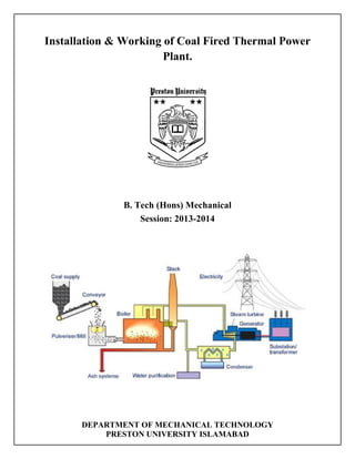
  • 14. 14 CHAPTERS:2 2.1 Introduction to C.F.T.P.P System How is Coal Converted to Electricity? Steam coal, also known as thermal coal, is used in power stations to generate electricity. Coal is first milled to a fine powder, which increases the surface area and allows it to burn more quickly. In these pulverised coal combustion (PCC) systems, the powdered coal is blown into the combustion chamber of a boiler where it is burnt at high temperature (see diagram below). The hot gases and heat energy produced converts water – in tubes lining the boiler – into steam. The high pressure steam is passed into a turbine containing thousands of propeller-like blades. The steam pushes these blades causing the turbine shaft to rotate at high speed. A generator is mounted at one end of the turbine shaft and consists of carefully wound wire coils. Electricity is generated when these are rapidly rotated in a strong magnetic field. After passing through the turbine, the steam is condensed and returned to the boiler to be heated once again. The electricity generated is transformed into the higher voltages (up to 400,000 volts) used for economic, efficient transmission via power line grids. When it nears the point of consumption, such as our homes, the electricity is transformed down to the safer 100-250 voltage systems used in the domestic market. A coal power station turns the chemical energy in coal into electrical energy that can be used in homes and businesses.
  • 15. 15 First the coal (1) is ground to a fine powder and blown into the boiler (2), where it is burned, converting its chemical energy into heat energy. Grinding the coal into powder increases its surface area, which helps it to burn faster and hotter, producing as much heat and as little waste as possible. As well as heat, burning coal produces ash and exhaust gases. The ash falls to the bottom of the boiler and is removed by the ash systems (3). It is usually then sold to the building industry and used as an ingredient in various building materials, like concrete. The gases enter the exhaust stack (4), which contains equipment that filters out any dust and ash, before venting into the atmosphere. The exhaust stacks of coal power stations are built tall so that the exhaust plume (5) can disperse before it touches the ground. This ensures that it does not affect the quality of the air around the station. Burning the coal heats water in pipes coiled around the boiler, turning it into steam. The hot steam expands in the pipes, so when it emerges it is under high pressure. The pressure drives the steam over the blades of the steam turbine (6), causing it to spin, converting the heat energy released in the boiler into mechanical energy. A shaft connects the steam turbine to the turbine generator (7), so when the turbine spins, so does the generator. The generator uses an electromagnetic field to convert this mechanical energy into electrical energy. After passing through the turbine, the steam comes into contact with pipes full of cold water. In coastal stations this water is pumped straight from the sea (8). The cold pipes cool the steam so that it condenses back into water. It is then piped back to the boiler, where it can be heated up again, turn into steam again, and keep the turbine turning. Finally, a transformer converts the electrical energy from the generator to a high voltage. The national grid uses high voltages to transmit electricity efficiently through the power lines (9) to the homes and businesses that need it (10). Here, other transformers reduce the voltage back down to a usable level. Efficiency Improvements Improvements continue to be made in conventional PCC power station design and new combustion technologies are being developed. These allow more electricity to be produced from less coal - known as improving the thermal efficiency of the power station. Efficiency gains in electricity generation from coal-fired power stations will play a crucial part in reducing CO2 emissions at a global level. Efficiency improvements include the most cost-effective and shortest lead time actions for reducing emissions from coal-fired power generation. This is particularly the case in developing countries where existing power plant efficiencies are generally lower and coal use in electricity generation is increasing. Not only do higher efficiency coal-fired power plants emit less carbon dioxide per megawatt (MW), they are also more suited to retrofitting with CO2 capture systems.
  • 16. 16 Improving the efficiency of pulverised coal-fired power plants has been the focus of considerable efforts by the coal industry. There is huge scope for achieving significant efficiency improvements as the existing fleet of power plants are replaced over the next 10-20 years with new, higher efficiency supercritical and ultra-supercritical plants and through the wider use of Integrated Gasification Combined Cycle (IGCC) systems for power generation. A one percentage point improvement in the efficiency of a conventional pulverised coal combustion plant results in a 2-3% reduction in CO2 emissions. 2.2 Coal
  • 17. 17 MOST COALS THAT ARE MINED FOR ENERGY PRODUCTION ARE HUMIC COALS WHICH ARE DERIVED FROM PEAT. THESE COALS ARE EXAMPLES OF ORGANIC SEDIMENTARY ROCKS AND COMPOSED OF SUBSTANCES OR AGGREGATES CALLED MACERALS. IF YOU LOOK AT THE PICTURE THE PICTURE OF A LUMP OF COAL, YOU CAN SEE STRATIFICATION WHICH RESULTS FROM THE ORGANIC MATTER BEING DEPOSITED LAYER UPON LAYER. THE FORMATION OF HUMIC COALS BEGINS WHEN PLANT DEBRIS ACCUMULATES IN A SWAMP WHERE THE STAGNANT WATER PREVENTS OXIDATION AND TOTAL DECOMPOSITION OF THE ORGANIC MATTER. THESE SWAMPS ARE CALLED PEAT SWAMPS. IT IS ESTIMATED THAT ABOUT 10% OF THE PLANT MATTER IS COVERTED TO PEAT IN THESE SWAMPS. IT APPEARS THAT MANY COAL DEPOSITS FORMED WHEN PEAT DEPOSITS IN NEAR- COASTAL BASINS SUBSIDED ALLOWING THE SEA TO FLOOD THE AREA COVERING THE PEAT WITH SAND AND MUD. MUCH OF THE AREA THAT NOW IS FOUND IN EUROPE AND NORTH AMERICA WERE LOCATED CLOSER TO THE EQUATOR DURING THE DEVONIAN AND CARBONIFEROUS PERIODS, AND THE SEAWATER WAS WARM ALLOWING LIME MUDS TO ACCUMULATE ON TOP OF THE PEAT DEPOSITS. OVER TIME THESE AREAS EXPERIENCED CYCLICAL PERIODS OF SUBSIDENCE AND REEMERGENCE. AS A RESULT MANY COAL DEPOSITS ARE COMPOSED OF LAYERS OF COAL SEPARATED BY LAYERS OF SANDSTONE, SHALE OR LIMESTONE. THE COAL LAYERS RANGE IN THICKNESS FROM A FEW CENTIMETERS TO 50 FEET OR MORE. ALTHOUGH COAL FORMATION BEGAN IN THE
  • 18. 18 DEVONIAN, THE GREAT COAL BEDS FOUND IN AUSTRALIA, THE EASTERN UNITED STATES AND ENGLAND WERE FORMED DURING THE CARBONIFEROUS PERIODSAND THOSE OF THE WESTERN U.S. WERE FORMED DURING THE JURASSIC TO THE MID-TERTIARY 2.3 Definition of Boiler Steam boiler or simply a boiler is basically a closed vessel into which water is heated until the water is converted into steam at required pressure. This is most basic definition of boiler. Working The basic working principle of boiler is very very simple and easy to understand. The boiler is essentially a closed vessel inside which water is stored. Fuel (generally coal) is bunt in a furnace and hot gasses are produced. These hot gasses come in contact with water vessel where the heat of these hot gases transfer to the water and consequently steam is produced in the boiler. Then this steam is piped to the turbine of thermal power plant. There are many different types of boiler utilized for different purposes like running a production unit, sanitizing some area, sterilizing equipment, to warm up the surroundings etc. 2.4 Turbine A working fluid contains potential energy (pressure head) and kinetic energy (velocity head). The fluid may be compressible or incompressible. Several physical principles are employed by turbines to collect this energy: Impulse turbines change the direction of flow of a high velocity fluid or gas jet. The resulting impulse spins the turbine and leaves the fluid flow with diminished kinetic energy. There is no pressure change of the fluid or gas in the turbine blades (the moving blades), as in the case of a steam or gas turbine, all the pressure drop takes place in the stationary blades (the nozzles). Before reaching the turbine, the fluid's pressure head is changed to velocity head by accelerating the fluid with a nozzle. Pelton wheels and de Laval turbines use this process exclusively. Impulse turbines do not require a pressure casement around the rotor since the fluid jet is created by the nozzle prior to reaching the blades on the rotor. Newton's second law describes the transfer of energy for impulse turbines.
  • 19. 19 Reaction turbines develop torque by reacting to the gas or fluid's pressure or mass. The pressure of the gas or fluid changes as it passes through the turbine rotor blades. A pressure casement is needed to contain the working fluid as it acts on the turbine stage(s) or the turbine must be fully immersed in the fluid flow (such as with wind turbines). The casing contains and directs the working fluid and, for water turbines, maintains the suction imparted by the draft tube. Francis turbines and most steam turbines use this concept. For compressible working fluids, multiple turbine stages are usually used to harness the expanding gas efficiently. Newton's third law describes the transfer of energy for reaction turbines. In the case of steam turbines, such as would be used for marine applications or for land- based electricity generation, a Parsons type reaction turbine would require approximately double the number of blade rows as a de Laval type impulse turbine, for the same degree of thermal energy conversion. Whilst this makes the Parsons turbine much longer and heavier, the overall efficiency of a reaction turbine is slightly higher than the equivalent impulse turbine for the same thermal energy conversion. In practice, modern turbine designs use both reaction and impulse concepts to varying degrees whenever possible. Wind turbines use an airfoil to generate a reaction lift from the moving fluid and impart it to the rotor. Wind turbines also gain some energy from the impulse of the wind, by deflecting it at an angle. Turbines with multiple stages may utilize either reaction or impulse blading at high pressure. Steam turbines were traditionally more impulse but continue to move towards reaction designs similar to those used in gas turbines. At low pressure the operating fluid medium expands in volume for small reductions in pressure. Under these conditions, blading becomes strictly a reaction type design with the base of the blade solely impulse. The reason is due to the effect of the rotation speed for each blade. As the volume increases, the blade height increases, and the base of the blade spins at a slower speed relative to the tip. This change in speed forces a designer to change from impulse at the base, to a high reaction style tip. Classical turbine design methods were developed in the mid 19th century. Vector analysis related the fluid flow with turbine shape and rotation. Graphical calculation methods were used at first. Formulae for the basic dimensions of turbine parts are well documented and a highly efficient machine can be reliably designed for any fluid flow condition. Some of the calculations are empirical or 'rule of thumb' formulae, and others are based on classical mechanics. As with most engineering calculations, simplifying assumptions were made. Turbine inlet guide vanes of a turbojet
  • 20. 20 Velocity triangles can be used to calculate the basic performance of a turbine stage. Gas exits the stationary turbine nozzle guide vanes at absolute velocity Va1. The rotor rotates at velocity U. Relative to the rotor, the velocity of the gas as it impinges on the rotor entrance is Vr1. The gas is turned by the rotor and exits, relative to the rotor, at velocity Vr2. However, in absolute terms the rotor exit velocity is Va2. The velocity triangles are constructed using these various velocity vectors. Velocity triangles can be constructed at any section through the blading (for example: hub, tip, midsection and so on) but are usually shown at the mean stage radius. Mean performance for the stage can be calculated from the velocity triangles, at this radius, using the Euler equation: Hence: where: specific enthalpy drop across stage turbine entry total (or stagnation) temperature turbine rotor peripheral velocity change in whirl velocity The turbine pressure ratio is a function of and the turbine efficiency. Modern turbine design carries the calculations further. Computational fluid dynamics dispenses with many of the simplifying assumptions used to derive classical formulas and computer software facilitates optimization. These tools have led to steady improvements in turbine design over the last forty years. The primary numerical classification of a turbine is its specific speed. This number describes the speed of the turbine at its maximum efficiency with respect to the power and flow rate. The specific speed is derived to be independent of turbine size. Given the fluid flow conditions and the desired shaft output speed, the specific speed can be calculated and an appropriate turbine design selected. The specific speed, along with some fundamental formulas can be used to reliably scale an existing design of known performance to a new size with corresponding performance
  • 21. 21 2.5 Generator An electric generator is a device that converts mechanical energy obtained from an external source into electrical energy as the output. It is important to understand that a generator does not actually ‘create’ electrical energy. Instead, it uses the mechanical energy supplied to it to force the movement of electric charges present in the wire of its windings through an external electric circuit. This flow of electric charges constitutes the output electric current supplied by the generator. This mechanism can be understood by considering the generator to be analogous to a water pump, which causes the flow of water but does not actually ‘create’ the water flowing through it. The modern-day generator works on the principle of electromagnetic induction discovered by Michael Faraday in 1831-32. Faraday discovered that the above flow of electric charges could be induced by moving an electrical conductor, such as a wire that contains electric charges, in a magnetic field. This movement creates a voltage difference between the two ends of the wire or electrical conductor, which in turn causes the electric charges to flow, thus generating electric current. Main components of a generator
  • 22. 22 The main components of an electric generator can be broadly classified as follows (refer to illustration above): (1) Engine (2) Alternator (3) Fuel System (4) Voltage Regulator (5) Cooling and Exhaust Systems (6) Lubrication System (7) Battery Charger (8) Control Panel (9) Main Assembly / Frame A description of the main components of a generator is given below. (1) Engine The engine is the source of the input mechanical energy to the generator. The size of the engine is directly proportional to the maximum power output the generator can supply. There are several factors that you need to keep in mind while assessing the engine of your generator. The manufacturer of the engine should be consulted to obtain full engine operation specifications and maintenance schedules. (a) Type of Fuel Used – Generator engines operate on a variety of fuels such as diesel, gasoline, propane (in liquefied or gaseous form), or natural gas. Smaller engines usually operate on gasoline while larger engines run on diesel, liquid propane, propane gas, or natural gas. Certain engines can also operate on a dual feed of both diesel and gas in a bi-fuel operation mode. (b) Overhead Valve (OHV) Engines versus non-OHV Engines – OHV engines differ from other engines in that the intake and exhaust valves of the engine are located in the head of the engine’s cylinder as opposed to being mounted on the engine block. OHV engines have several advantages over other engines such as: • Compact design • Simpler operation mechanism • Durability • User-friendly in operations • Low noise during operations • Low emission levels However, OHV-engines are also more expensive than other engines.
  • 23. 23 (c) Cast Iron Sleeve (CIS) in Engine Cylinder – The CIS is a lining in the cylinder of the engine. It reduces wear and tear, and ensures durability of the engine. Most OHV-engines are equipped with CIS but it is essential to check for this feature in the engine of a generator. The CIS is not an expensive feature but it plays an important role in engine durability especially if you need to use your generator often or for long durations. 2.6 Power Supply A power supply is an electronic device that supplies electric energy to an electrical load. The primary function of a power supply is to convert one form of electrical energy to another and, as a result, power supplies are sometimes referred to as electric power converters. Some power supplies are discrete, stand-alone devices, whereas others are built into larger devices along with their loads. Examples of the latter include power supplies found in desktop computers and consumer electronics devices. Every power supply must obtain the energy it supplies to its load, as well as any energy it consumes while performing that task, from an energy source. Depending on its design, a power supply may obtain energy from various types of energy sources, including electrical energy transmission systems, energy storage devices such as a batteries and fuel cells, electromechanical systems such as generators and alternators, solar power converters, or another power supply. All power supplies have a power input, which receives energy from the energy source, and a power output that delivers energy to the load. In most power supplies the power input and output consist of electrical connectors or hardwired circuit connections, though some power supplies employ wireless energy transfer in lieu of galvanic connections for the power input or output. Some power supplies have other types of inputs and outputs as well, for functions such as external monitoring and control.
  • 24. 24 CHAPTERS:3 Thermal Coal 3.1 Introduction Coal (from the Old English term col, which has meant "mineral of fossilized carbon" since the 13th century)[1] is a combustible black or brownish-black sedimentary rock usually occurring in rock strata in layers or veins called coal beds or coal seams. The harder forms, such as anthracite coal, can be regarded as metamorphic rock because of later exposure to elevated temperature and pressure. Coal is composed primarily of carbon along with variable quantities of other elements, chiefly hydrogen, sulfur, oxygen, and nitrogen.[2] Throughout history, coal has been used as an energy resource, primarily burned for the production of electricity and/or heat, and is also used for industrial purposes, such as refining metals. A fossil fuel, coal forms when dead plant matter is converted into peat, which in turn is converted into lignite, then sub-bituminous coal, after that bituminous coal, and lastly anthracite. This involves biological and geological processes that take place over a long period. The Energy Information Administration estimates coal reserves at 948×109 short tons (860 Gt).[3] One estimate for resources is 18 000 Gt.[4] Coal is the largest source of energy for the generation of electricity worldwide, as well as one of the largest worldwide anthropogenic sources of carbon dioxide releases. In 1999, world gross carbon dioxide emissions from coal usage were 8,666 million tonnes of carbon dioxide.[5] In 2011, world gross emissions from coal usage were 14,416 million tonnes.[6] Coal-fired electric power generation emits around 2,000 pounds of carbon dioxide for every megawatt-hour generated, which is almost double the approximately 1100 pounds of carbon dioxide released by a natural gas-fired electric plant per megawatt-hour generated. Because of this higher carbon efficiency of natural gas generation, as the market in the United States has changed to reduce coal and increase natural gas generation, carbon dioxide emissions have fallen. Those measured in the first quarter of 2012 were the lowest of any recorded for the first quarter of any year since 1992.[7] In 2013, the head of the UN climate agency advised that most of the world's coal reserves should be left in the ground to avoid catastrophic global warming.[8] Coal is extracted from the ground by coal mining, either underground by shaft mining, or at ground level by open pit mining extraction. Since 1983 the world top coal producer has been China.[9] In 2011 China produced 3,520 millions of tonnes of coal – 49.5% of 7,695 millions tonnes world coal production. In 2011 other large producers were United States (993 millions tonnes), India (589), European Union (576) and Australia (416).[9] In 2010 the largest exporters were Australia with 328 million tonnes (27.1% of world coal export) and Indonesia with 316 millions tonnes (26.1%),[10] while the largest importers were Japan with 207 million tonnes (17.5% of world coal import), China with 195 million tonnes (16.6%) and South Korea with 126 million tonnes
  • 25. 25 3.2 Thermal coal Coal is primarily used as a solid fuel to produce electricity and heat through combustion. World coal consumption was about 7.25 billion tonnes in 2010 (7.99 billion short tons) and is expected to increase 48% to 9.05 billion tonnes (9.98 billion short tons) by 2030.[38] China produced 3.47 billion tonnes (3.83 billion short tons) in 2011. India produced about 578 million tonnes (637.1 million short tons) in 2011. 68.7% of China's electricity comes from coal. The USA consumed about 13% of the world total in 2010, i.e. 951 million tonnes (1.05 billion short tons), using 93% of it for generation of electricity 46% of total power generated in the USA was done using coal. When coal is used for electricity generation, it is usually pulverized and then combusted (burned) in a furnace with a boiler.[41] The furnace heat converts boiler water to steam, which is then used to spin turbines which turn generators and create electricityThe thermodynamic efficiency of this process has been improved over time; some older coal- fired power stations have thermal efficiencies in the vicinity of 25% whereas the newest supercritical and "ultra-supercritical" steam cycle turbines, operating at temperatures over 600 °C and pressures over 27 MPa (over 3900 psi), can practically achieve thermal efficiencies in excess of 45% (LHV basis) using anthracite fuel,[44][45] or around 43% (LHV basis) even when using lower-grade lignite fuel.[46] Further thermal efficiency improvements are also achievable by improved pre-drying (especially relevant with high- moisture fuel such as lignite or biomass) and cooling technologies.[47] An alternative approach of using coal for electricity generation with improved efficiency is the integrated gasification combined cycle (IGCC) power plant. Instead of pulverizing the coal and burning it directly as fuel in the steam-generating boiler, the coal can be first gasified (see coal gasification) to create syngas, which is burned in a gas turbine to produce electricity (just like natural gas is burned in a turbine). Hot exhaust gases from the turbine are used to raise steam in a heat recovery steam generator which powers a supplemental steam turbine. Thermal efficiencies of current IGCC power plants range from 39-42% (HHV basis) or ~42-45% (LHV basis) for bituminous coal and assuming utilization of mainstream gasification technologies (Shell, GE Gasifier, CB&I). IGCC power plants outperform conventional pulverized coal-fueled plants in terms of pollutant emissions, and allow for relatively easy carbon capture. At least 40% of the world's electricity comes from coal, and in 2012, about one-third of the United States' electricity came from coal, down from approximately 49% in 2008. As of 2012 in the United States, use of coal to generate electricity was declining, as plentiful supplies of natural gas obtained by hydraulic fracturing of tight shale formations became available at low prices. In Denmark, a net electric efficiency of > 47% has been obtained at the coal-fired Nordjyllandsværket CHP Plant and an overall plant efficiency of up to 91% with cogeneration of electricity and district heating. The multifuel-fired Avedøreværket CHP Plant just outside Copenhagen can achieve a net electric efficiency as high as 49%. The
  • 26. 26 overall plant efficiency with cogeneration of electricity and district heating can reach as much as 94%. An alternative form of coal combustion is as coal-water slurry fuel (CWS), which was developed in the Soviet Union. CWS significantly reduces emissions, improving the heating value of coal.[citation needed] Other ways to use coal are combined heat and power cogeneration and an MHD topping cycle. The total known deposits recoverable by current technologies, including highly polluting, low-energy content types of coal (i.e., lignite, bituminous), is sufficient for many years.[quantify] However, consumption is increasing and maximal production could be reached within decades (see world coal reserves, below). On the other hand much may have to be left in the ground to avoid climate change. 3.3 Types of Coal We use the term "coal" to describe a variety of fossilized plant materials, but no two coals are exactly alike. Heating value, ash melting temperature, sulfur and other impurities, mechanical strength, and many other chemical and physical properties must be considered when matching specific coals to a particular application. Coal is classified into four general categories, or "ranks." They range from lignite through subbituminous and bituminous to anthracite, reflecting the progressive response of individual deposits of coal to increasing heat and pressure. The carbon content of coal supplies most of its heating value, but other factors also influence the amount of energy it contains per unit of weight. (The amount of energy in coal is expressed in British thermal units per pound. A BTU is the amount of heat required to raise the temperature of one pound of water one degree Fahrenheit.) About 90 percent of the coal in this country falls in the bituminous and subbituminous categories, which rank below anthracite and, for the most part, contain less energy per unit of weight. Bituminous coal predominates in the Eastern and Mid-continent coal fields, while subbituminous coal is generally found in the Western states and Alaska. Lignite ranks the lowest and is the youngest of the coals. Most lignite is mined in Texas, but large deposits also are found in Montana, North Dakota, and some Gulf Coast states.
  • 27. 27 Anthracite Anthracite is coal with the highest carbon content, between 86 and 98 percent, and a heat value of nearly 15,000 BTUs-per-pound. Most frequently associated with home heating, anthracite is a very small segment of the U.S. coal market. There are 7.3 billion tons of anthracite reserves in the United States, found mostly in 11 northeastern counties in Pennsylvania. Bituminous The most plentiful form of coal in the United States, bituminous coal is used primarily to generate electricity and make coke for the steel industry. The fastest growing market for coal, though still a small one, is supplying heat for industrial processes. Bituminous coal has a carbon content ranging from 45 to 86 percent carbon and a heat value of 10,500 to 15,500 BTUs-per-pound. Subbituminous Ranking below bituminous is subbituminous coal with 35-45 percent carbon content and a heat value between 8,300 and 13,000 BTUs-per-pound. Reserves are located mainly in a half-dozen Western states and Alaska. Although its heat value is lower, this coal generally has a lower sulfur content than other types, which makes it attractive for use because it is cleaner burning Lignite Lignite is a geologically young coal which has the lowest carbon content, 25-35 percent, and a heat value ranging between 4,000 and 8,300 BTUs-per-pound. Sometimes called brown coal, it is mainly used for electric power generation.
  • 28. 28 CHAPTERS:4 Boiler 4.1 Introduction A boiler is a closed vessel in which water under pressure is transformed into steam by the application of heat. In the boiler furnace, the chemical energy in the fuel is converted into heat, and it is the function of the boiler to transfer this heat to the contained water in the most efficient manner. The boiler should also be designed to generate high quality steam for plant use. A flow diagram for a typical boiler plant is presented in A boiler must be designed to absorb the maximum amount of heat released in the process of combustion. This heat is transferred to the boiler water through radiation, conduction and convection. The relative percentage of each is dependent upon the type of boiler, the designed heat transfer surface and the fuels. 4.2 Classification of boiler 1. Horizontal, Vertical or Inclined Boiler. 2. Fire Tube and Water Tube 3. Externally Fired and Internally Fired 4. Forced circulation and Natural Circulation 5. Higher Pressure and Low Pressure Boilers 6. Stationary and Portable 7. Single Tube and Multi Tube Boiler 1. Horizontal, Vertical or Inclined Boiler. If the axis of the boiler is horizontal,the boiler is called horizontal, if the axis is vertical, it is called verticalboiler and if the axis is inclined it is called as inclined boiler.The parts of horizontal boiler is can be inspected and repaired easily but it occupies more space.The vertical boiler occupies less floor area.
  • 29. 29 2. Fire Tube and Water Tube In the fire boilers, the hot gases are inside the tubes and the water surrounds the tubes. Examples: Cochran, Lancashire and Locomotive boilers. In the water tube boilers, the water is inside the tubes and hot gases surround them. Examples: Babcock and Wilcox, Stirling, Yarrow boiler etc. 3. Externally Fired and Internally Fired The boiler is known as externally fired if the fire is outside the shell. Examples: Babcock and Wilcox boiler,Stirling boiler etc. In case of internally fired boilers, the furnace is located inside the shell. Examples: Cochran, Lancashire boiler etc. 4. Forced circulation and Natural Circulation In forced circulation type of boilers, the circulation of water is done by a forced pump. Examples: Velox, Lamomt,Benson Boiler etc. In natural circulation type of boilers, circulation of water in the boiler takes place due to natural convention currents produced by the application of heat. Examples: Lancashire, Babcock and Wilcox boiler etc. 5. Higher Pressure and Low Pressure Boilers The boiler which produce steam at pressures of 80 bar and above are called high pressure boilers. Examples: Babcock and Wilcox, Velox,Lamomt,Benson Boiler etc. The boilers which produce steam at pressure below 80 bar are called low pressure boilers. Examples: Cochran, Cornish, Lancashire and Locomotive boiler etc. 6. Stationary and Portable • Primarily, the boilers are classified as either stationary or mobile.
  • 30. 30 • Stationary boilers are used for power plant steam, for central station utility power plants, for plant process steam etc. • Mobile boilers or portable boilers include locomotive type, and other small units for temporary use at sites. 7. Single Tube and Multi Tube Boiler The fire tube boilers are classified as single tube and multi-tube boilers, depending upon whether the fire tube is one or more than one. Examples: Cornish ,simple vertical boiler are the single tube boiler and rest of the boilers are multi-tube boiler. 4.3 Types of boiler 1. Condensing boilers Condensing boilers are by far the most common boiler type in UK homes, and are far more energy-efficient than older mains gas boilers, using around 90% of their heat. A condensing boiler works by passing hot gas through a central chamber that heats up water but, cleverly, a second chamber uses remaining heat to warm up water coming back into the unit from the heating system. Of all the condensing boiler types, the combi-boiler is the most popular. A combi-boiler includes the hot water unit and cold water tank in the same unit, which means all your hot water and heating come from the same unit. This makes it easy to install. It also means you get a steady supply of hot water through your taps as you don’t have to wait for the tank to fill and don’t have to worry about lots of space for different tanks. The downsides lie in the fact that, as they are a small unit, you will only get maximum pressure through one tap at a time, and they struggle to produce large quantities of hot water. Heat-only boilers, in comparison, have a more traditional approach by offering hot water only, whilst cold water is supplied separately. This does away with some of the problems of supply and water pressure. But, because the hot- and cold-water systems are separate, they take up more space, and are less energy-efficient. 2. Oil boilers Oil boilers represent an alternative to the estimated four million homes across the UK that are not connected to mains gas. This isolation comes at a cost however, and an oil boiler will typically be a few hundred pounds a year more expensive to run than gas.
  • 31. 31 In terms of the mechanics, oil boilers are fairly similar to traditional boilers. Instead just using oil rather than gas to heat the inner pipes and, thereby, the water. The main difference comes in when you try and get your hands on the oil itself. The oil has to be delivered to your home, making oil boilers more logistically challenging. Prices do also vary for heating oil or kerosene, so you may have to shop around to get a good deal. Maintenance can also be an issue because, if you run into any problems, you will need to get an Oftec registered engineer in to inspect it (rather than a Gas Safety Register engineer for conventional gas boilers). 3. Biomass boilers A biomass boiler, or wood boiler, is the other main alternative and, as the name suggests, relies on wood pellets, chips or logs to generate heat. Wood pellet boilers are very cheap in comparison to the other alternatives, costing an estimated £600 a year to run, and are energy-efficient. The carbon dioxide given off by wood pellet boilers is similar to that absorbed by new plants, so it is a sustainable fuel. Pellets are the most practical solution for biomass boilers even though logs are cheaper, as they can be automatically fed in to the system. You will have to find a supplier for your pellets though. The Energy Saving Trust estimates installation costs between £7,000 and £13,000, and a tonne of wood pellets can cost under £200. They emit around 3 tonnes fewer of carbon dioxide a year compared to a gas boiler, but there are some things to be aware of. Unlike gas or oil boilers, a wood pellet boiler will generate ash, so you will have to empty it out approximately once a week. The ash may be self-cleaned depending on the boiler, but if you don’t keep it clean it could shut down. Biomass boilers tend to be slightly bigger than gas or oil boilers and you will also need somewhere to store the heating fuel. Likewise, you will need a flue or chimney, which may mean you need planning permission, so be sure to check the regulations for your property in advance. You will also need to maintain the flue pipe or chimney to keep it clean of soot deposits.
  • 32. 32 4.4 Working of boiler A boiler is water containing vessel which transfers heat from a fuel source (oil, gas, coal) into steam which is piped to a point where it can be used to run production equipment, to sterilize, provide heat, to steam-clean, etc. The energy given up by the steam is sufficient to convert it back into the form of water. When 100% of the steam produced is returned to be reused, the system is called a closed system. Examples of closed systems are closed steam heating, hot water heating, and "one-pipe" systems. Since some processes can contaminate the steam, so it is not always desirable to feed the condensate back into the boiler. A system that does not return the condensate is called an open system The two main types of boilers are:  Firetube - the fire or hot gases are directed through the inside of tubes within the boiler shell, which are surrounded by water. The tubes are arranged in banks so that the gases can be passed through the boiler up to 4 times before passing out the stack. This system exposes the maximum heat transfer surface to the water. Firetube boilers are also known as shell boilers and can produce up to approximately 750 hp or 25,000 lbs of steam per hour. 80% of boilers in use are of
  • 33. 33 this configuration.  A subtype of this boiler is the packaged boiler, shipped complete with fuel burning equipment, mechanical draft equipment, automatic controls and accessories and is designed to function automatically with a very minimum of attention. It is particularly important to prevent scale formation in this type of boiler.  Watertube - the fire or hot gases are directed to and around the outside of tubes containing water, arranged in a vertical position. Watertube boilers are usually rectangular in shape and have two or more drums. The separation of steam and water takes place in the top drum, while the bottom drum serves as a collection point for sludge. This system is usually used when more than 750 hp or several hundred thousand lbs of steam per hour, are needed.  There are other designs with special configurations, adapting them to particular applications. The boiler usually sits on top of a burner in which fuel is burned to produce heat. The fuel produces the heat, the water or steam in the boiler is used to distribute the heat through the house usually via pipes and radiators. The most common fuel for boilers in the United States today is natural gas which is usually piped directly into the house from a pipeline that runs under the street or road. In rural areas not served by natural gas lines the most common fuel for boilers is propane gas which is kept in a large tank in the yard and piped into the house. Propane is usually more expensive than natural gas. In some areas of the US mainly New England there are some boilers that are heated by fuel or heating oil. Outside of the Northeast oil fired boilers are actually very rare. Many oil fired boilers have been converted to burn natural gas or propane. The reason natural gas and propane are more popular is that they are much cheaper fuels. There are also a small number of boilers around that burn other fuels. Before Word War II many boilers burnt coal. Today, some people particularly in rural areas burn wood because it is often cheaper than natural gas or propane. There are also boilers that burn other more exotic fuels such as waste oil, wood pellets and even corn cobs 1. Fire Tube Boiler 2. Water Tube Boiler Fire tube or "fire in tube" boilers; contain long steel tubes through which the hot gasses from a furnace pass and around which the water to be converted to steam circulates. (Refer Figure 2.2). Fire tube boilers, typically have a lower initial cost, are more fuel efficient and easier to
  • 34. 34 operate, but they are limited generally to capacities of 25 tons/hr and pressures of 17.5 kg/cm2. Water tube or "water in tube" boilers in which the conditions are reversed with the water passing through the tubes and the hot gasses passing outside the tubes (see figure 2.3). These boilers can be of single- or multiple-drum type. These boilers can be built to any steam capacities and pressures, and have higher efficiencies than fire tube boilers. WATER-TUBE BOILERS Water-tube boilers may be classified in a number ofways. For our purpose, they are classified as either straight tube or bent tube. These classes are discussed separately in succeeding sections. To avoid confusion,make sure you study carefully each illustration referred to throughout the discussion. Straight Tube The STRAIGHT-TUBE class of water-tube boilers includes three types: 1. Sectional-header cross drum 2. Box-header cross drum’ 3. Box-header longitudinal drum In the SECTIONAL-HEADER CROSS DRUM boiler with vertical headers, the headers are steel boxesinto which the tubes are rolled. Feedwater enters andpasses down through the downcomers (pipes) into therear sectional headers from which the tubes are supplied.The water is heated and some of it changes into steam as itflows through the tubes to the front headers. The steam-water mixture returns to the steam drum throughthe circulating tubes and is discharged in front of thesteam-drum baffle that helps to separate the water andsteam. Steam is removed from the top of the drum throughthe dry pipe. This pipe extends along the length of thedrum and has holes or slots in the top half for steam toenter. Headers, the distinguishing feature of this boiler. areusually made of forged steel and are connected to thedrums with tubes. Headers may be vertical or at rightangles to the tubes. The tubes are rolled and flared intothe header. A handhold is located opposite the ends ofeach tube to facilitate inspection and cleaning. Itspurpose is to collect sediment that is removed by blowingdown the boiler. Baffles are usually arranged so gases are directedacross the tubes three times before being discharged fromthe boiler below the drum.
  • 35. 35 BOX-HEADER CROSS DRUM boilers are shallowboxes made of two plates—a tube-sheet plate that is bentto form the sides of the box, and a plate containing thehandholds that is riveted to the tube-sheet plate. Some aredesigned so that the front plate can be removed for accessto tubes. Tubes enter at right angles to the box header andare expanded and flared in the same manner as thesectional-header boiler. The boiler is usually built withthe drum in front. It is supported by lugs fastened to thebox headers. This boiler has either cross or longitudinalbaffling arranged to divide the boiler into three passes.Water enters the bottom of the drum, flows throughconnecting tubes to the box header, through the tubes tothe rear box header, and back to the drum. BOX-HEADER LONGITUDINAL DRUM boilers have either a horizontal or inclined drum. Boxheaders are fastened directly to the drum when thedrum is inclined. When the drum is horizontal, thefront box header is connected to it at an angle greaterthan 90 degrees. The rear box header is connected tothe drum by tubes. Longitudinal or cross baffles can beused with either type. Bent Tube Bent tube boilers usually have three drums. Thedrums are usually of the same diameter and positioned atdifferent levels with each other. The uppermost orhighest positioned drum is referred to as the STEAMDRUM, while the middle drum is referred to as theWATER DRUM, and the lowest, the MUD DRUM. Tubebanks connect the drums. The tubes are bent at the ends toenter the drums radially. Water enters the top rear drum, passes through thetubes to the bottom drum, and then moves up through thetubes to the top front drum. A mixture of steam and wateris discharged into this drum. The steam returns to the toprear drum through the upper row of tubes, while the watertravels through the tubes in the lower rear drum by tubesextending across the drum and enters a small collectingheader above the front drum. Many types of baffle arrangements are used withbent-tube boilers. Usually, they are installed so that theinclined tubes between the lower drum and the top frontdrum absorb 70 to 80 percent of the heat. The water-tubeboilers discussed above offer a number of worthwhileadvantages. For one thing, they afford flexibility instarting up. They also have a high productive capacityranging from 100.000 to 1,000,000 pounds of steam perhour. In case of tube failure, there is little danger of adisastrous explosion of the water-tube boiler. Thefurnace not only can carry a high overload, it can also bemodified for tiring by oil or coal. Still another advantageis that it is easy to get into sections inside the furnace toclean and repair them.There are also several disadvantages common to water-tube boilers. One of themain drawbacks of water-tube boilers is their highconstruction cost. The large assortment of tubes requiredof this boiler and the excessive weight per unit weight ofsteam generated are other unfavorable factors. FIRE-TUBE BOILERS There are four types of fire-tube boiler. 1. Scotch Marine Boiler 2. Vertical-Tube Boiler
  • 36. 36 3. Horizontal Return Tubular Boiler 4. Firebox Boiler These fourtypes of boilers are discussed in this section. Scotch Marine Boiler The Scotch marine tire-tube boiler is especiallysuited to Seabee needs. Figure 1-1 is a portable Scotchmarine tire-tube boiler. The portable unit can be movedeasily and requires only a minimal amount of foundationwork.As a complete self-contained unit. its designincludes automatic controls. a steel boiler. and burnerequipment. These features are a big advantage becauseno disassembly is required when you must move theboiler into the field for an emergency. The Scotch marine boiler has a two-pass (or more)arrangement of tubes that run horizontally to allow theheat inside the tubes to travel back and forth. It also hasan internally fired furnace with a cylindrical combustionchamber. Oil is the primary fuel used to fire the boiler;however. it can also be fired with wood, coal, or gas. Amajor advantage of the Scotch marine boiler is that itrequires less space than a water-tube boiler and can beplaced in a room that has a low ceiling. The Scotch marine boiler also has disadvantages.The shell of the boiler runs from 6 to 8 feet in diameter, adetail of construction that makes a large amount ofreinforcing necessary.The fixed dimensions of theinternal surface cause some difficulty in cleaning thesections below the combustion chamber.Anotherdrawback is the limited capacity and pressure of theScotch marine boiler. An important safety device sometimes used is thefusible plug that provides added protection againstlow-water conditions. In case of a low-water condition.the fusible plug core melts, allowing steam to escape, anda loud noise is emitted which provides a warning to theoperator. On the Scotch boiler the plug is located in thecrown sheet, but sometimes it is placed in the upper backof the combustion chamber. Fusible plugs are discussedin more detail later in this chapter. Access for cleaning, inspection, and repair of theboiler watersides is provided through a manhole in thetop of the boiler shell and a handhold in the water leg. Themanhole opening is large enough for a man
  • 37. 37 to enter the boiler shell for inspection, cleaning, and repairs. On suchoccasions, always ensure that all valves are secured,locked, tagged, and that the person in charge knows youare going to enter the boiler. Additionally, always have aperson located outside of the boiler standing by to aid youin case of an incident occurring that would require you toneed assistance.The handholds are openings largeenough to permit hand entry for cleaning, inspection, andrepairs to tubes and headers.Figure 1-2 shows ahorizontal fire-tube boiler used in low-pressure applications. Personnel in the Utilitiesman rating areassigned to operate and maintain this type of boiler moreoften than any other type of boiler. Vertical-Tube Boiler In some fire-tube boilers, the tubes run vertically, asopposed to the horizontal arrangement in the Scotchboiler. The VERTICAL-TUBE boiler sits in an uprightposition, as shown in figure 1-3. Therefore, the productsof combustion (gases) make a single pass, travelingstraight up through the tubes and out the stack. The vertical fire-tube boiler is similar to the horizontalfire-tube boiler in that it is a portable, self-contained unitrequiring a minimum of floor space. Handholds are alsoprovided for cleaning and repairing. Thoughself-supporting in its setting (no brickwork or foundationbeing necessary), it MUST be level. The verticalfire-tube boiler has the same disadvantages as that of the horizontal-tube design—limited capacity and furnace volume 1. VENTS 7. WATER LEVEL GAUGE 2. AIR DAMPER 8. BURNER SWlTCH 3. HIGH-LIMIT PRESSURE CONTROL 9. PRIMING TEE 4. STEAM PRESSURE GAUGE 10. OIL UNIT, TWO STAGE
  • 38. 38 5. GAUGE GLASS SHUTOFF COCK 11. SOLENOID OIL VALVE 6. LOW-WATER CONTROL 12. SERVICE CONNECTION BOX 13. FUEL OIL SUPPLY CONNECTION 14. FUEL OIL PRESSURE GAUGE 15. FUEL OIL PRESSURE GAUGE 16. IGNITION CABLE 17. IGNITION CABLE16 IGNITION CABLE 18. NAMEPLATE18. BLOWER MOTOR Before selecting a vertical fire-tube boiler, you must know how much overhead space is in the building where it will be used. Since this boiler sits in an upright position, a room with a high ceiling is necessary for its installation. The blowdown pipe of the vertical tire-tube boiler is attached to the lowest part of the water leg. and the feedwater inlet opens through the top of the shell. The boiler fusible plug is installed either (1) in the bottom tube sheet or crown sheet or (2) on the outside row of tubes, one third of the height of the tube from the bottom. Horizontal Return Tubular Boiler In addition to operating portable boilers, such as the Scotch marine and vertical fire-tube boilers. the Utilitiesman must also be able to operate stationary boilers, both in the plant and in the field. A STATIONARY BOILER can be defined as one having a permanent foundation and not easily moved or relocated. A popular type of stationary fire-tube boiler is the HORIZONTAL RETURN TUBULAR (HRT) boiler shown in figure 1-4.
  • 39. 39 The initial cost of the HRT boiler is relatively low and installing it is not too difficult. The boiler setting can be readily changed to meet different fuel requirements—coal, oil, wood, or gas. Tube replacement is also a comparatively easy task since all tubes in the HRT boiler are the same in size, length, and diameter. The gas flows in the HRT boiler from the firebox to the rear of the boiler. It then returns through the tubes to the front where it is discharged to the breaching and out the stack. The HRT boiler has a pitch of 1 to 2 inches to the rear to allow sediment to settle toward the rear near the bottom blowdown connection. The fusible plug is located 2 inches above the top row of tubes. Boilers over 40 inches in diameter require a manhole in the upperpart of the shell. Those over 48 inches in diameter must have a manhole in the lower, as well as in the upper, part of the shell. Do not fail to familiarize yourself with the location of these and other essential parts of the HRT boiler. The knowledge you acquire will definitely help in the performance of your duties with boilers. Firebox Boiler Another type of fire-tube boiler is the FIREBOX boiler that is usually used for stationary purposes. A split section of a small firebox boiler is shown in figure 1-5. Gases in the firebox boiler make two passes through thetubes. Firebox boilers require no setting except possiblyan ash pit for coal fuel. As a result, they can be quicklyinstalled and placed in service. Gases travel from thefirebox through a group of tubes to a reversing chamber.They return through a second set of tubes to the flueconnection on the front of the boiler and are thendischarged up the stack.
  • 40. 40 Packaged Boiler: The packaged boiler is so called because it comes as a complete package. Once delivered to site, it requires only the steam, water pipe work, fuel supply and electrical connections to be made for it to become operational. Package boilers are generally of shell type with fire tube design so as to achieve high heat transfer rates by both radiation and convection (Refer Figure 2.4). The features of package boilers are:  Small combustion space and high heat release rate resulting in faster evaporation.  Large number of small diameter tubes leading to good convective heat transfer.  Forced or induced draft systems resulting in good combustion efficiency.  Number of passes resulting in better overall heat transfer.  Higher thermal efficiency levels compared with other boilers. These boilers are classified based on the number of passes - the number of times the hot combustion gases pass through the boiler. The combustion chamber is taken, as the first pass after which there may be one, two or three sets of fire-tubes. The most common boiler of this class is a three-pass unit with two sets of fire-tubes and with the exhaust gases exiting through the rear of the boiler. Stoker Fired Boiler: Stokers are classified according to the method of feeding fuel to the furnace and by the type of grate. The main classifications are: 1. Chain-grate or traveling-grate stoker 2. Spreader stoker Chain-Grate or Traveling-Grate Stoker Boiler Coal is fed onto one end of a moving steel chain grate. As grate moves along the length of the furnace, the coal burns before dropping off at the end as ash. Some
  • 41. 41 degree of skill is required, particularly when setting up the grate, air dampers and baffles, to ensure clean combustion leaving minimum of unburnt carbon in the ash. The coal-feed hopper runs along the entire coal-feed end of the furnace. A coal grate is used to control the rate at which coal is fed into the furnace, and to control the thickness of the coal bed and speed of the grate. Coal must be uniform in size, as large lumps will not burn out completely by the time they reach the end of the grate. As the bed thickness decreases from coal-feed end to rear end, different amounts of air are required- more quantity at coal-feed end and less at rear end (see Figure 2.5). Spreader Stoker Boiler Spreader stokers utilize a combination of suspension burning and grate burning. The coal is continually fed into the furnace above a burning bed of coal. The coal fines are burned in suspension; the larger particles fall to the grate, where they are burned in a thin, fast-burning coal bed. This method of firing provides good flexibility to meet load fluctuations, since ignition is almost instantaneous when firing rate is increased. Hence, the spreader stoker is favored over other types of stokers in many industrial applications. Pulverized Fuel Boiler Most coal-fired power station boilers use pulverized coal, and many of the larger industrial water- tube boilers also use this pulverized fuel. This technology is well developed, and there are thousands of units around the world, accounting for well over 90% of coal-fired capacity. The coal is ground (pulverised) to a fine powder, so that less than 2% is +300 micro metre (μm) and 70-75% is below 75 microns, for a bituminous coal. It should be noted that too fine a powder is wasteful of grinding mill power. On the other hand, too coarse a powder does not burn completely in the combustion chamber and results in higher unburnt losses. The pulverised coal is blown with part of the combustion air into the boiler plant through a series of burner nozzles. Secondary and tertiary air may also be added. Combustion takes place at temperatures from 1300-1700°C, depending largely on coal grade. Particle residence time in the boiler is typically 2 to 5 seconds, and the particles must be small enough for complete combustion to have taken place during this time. This system has many advantages such as ability to fire varying quality of coal, quick responses to changes in load, use of high pre-heat air temperatures etc.
  • 42. 42 One of the most popular systems for firing pulverized coal is the tangential firing using four burners corner to corner to create a fireball at the center of the furnace (see Figure 2.6). FBC Boiler When an evenly distributed air or gas is passed upward through a finely divided bed of solid particles such as sand supported on a fine mesh, the particles are undisturbed at low velocity. As air velocity is gradually increased, a stage is reached when the individual particles are suspended in the air stream. Further, increase in velocity gives rise to bubble formation, vigorous turbulence and rapid mixing and the bed is said to be fluidized. If the sand in a fluidized state is heated to the ignition temperature of the coal and the coal is injected continuously in to the bed, the coal will burn rapidly, and the bed attains a uniform temperature due to effective mixing. Proper air distribution is vital for maintaining uniform fluidisation across the bed.). Ash is disposed by dry and wet ash disposal systems. Fluidised bed combustion has significant advantages over conventional firing systems and offers multiple benefits namely fuel flexibility, reduced emission of noxious pollutants such as SOx and NOx, compact boiler design and higher combustion efficiency.
  • 43. 43 CHAPTERS:5 Turbine 5.1 Introduction of Turbine The British Government and the EU demands that the quantity electricity generated using fossil fuels be greatly reduced. The "green" alternatives such as wind wave and solar power are Dependant on climatic conditions and tidal power has great difficulty in generating continually over a 24 hour period. This is a real problem to the electricity supply companies who need to ensure that the demand for electricity can always be met This is no difficulty at present, since the quantity of "Green " electricity produced is not a significant percentage of the total, but as the number of wind farms increase, this will change. In many countries the majority of the power generation relies on steam turbines. These are highly efficient BUT inflexible. Basically they have to be kept spinning and they can not be quickly shut down or started. A turbine is a rotary engine that extracts energy from a fluid flow and converts it into useful work. Hydro electricity a reliable form of renewable energy. Water turbines are highly efficient and easily controlled to provide power as and when it is needed. In addition, currently the only system available to store large quantities of electrical power, is pumped storage. This involves pumping water into a high level reservoir. This can happen when the demand for electricity is low, at night for-instance. When the demand is high the supply can be rapidly increased by running the stored water through Turbines. – An IntroductionA turbine is a rotary mechanical device that extracts energy from afluid flow and converts it into useful work, namely electricity. 2. Turbine Blade 3. Turbines have been used for centuries to convert freely availablemechanical energy from rivers and wind into useful work, through arotating shaft.Classification of turbines based on working fluid:When the working fluid is water turbines are called hydraulic turbinesor hydroturbines.When working fluid is air, and energy is extracted from the wind, themachine is called wind turbine.When the working fluid is steam, turbines are called steam turbines.A more generic name for turbines that employ a compressible gas asthe working fluid is gas turbines. 4. Hydraulic Turbine Steam Turbine• Steam turbines are used for the generation of electricity in thermal power plants, such as plants using coal, fuel oil or nuclear power. s, in contrast with acondensable vapour in the steam turbine, produced in a gas generator athigh pressure by
  • 44. 44 continuous combustion in a combustion chamber. Gas Turbine used for electricity generation Working of a Gas Turbine to generate electricity Gas Turbine in Jet Engines nhow they operate – Impulse Turbines and Reaction Turbines. Mosthydro stations use either of these two turbines to produce electricity.• In an Impulse turbine, the whole of the available energy of the fluid is converted to Kinetic Energy before the water acts on the moving parts of the turbine.• Pelton Wheel is an example of such turbine. Pelton Wheel (Impulse Turbine) these cups by one or more jets mounted in thesurrounding casing. Momentum is transferred from water to cups,and a torque is created, causing the wheel to rotate.This type of turbine is highly efficient. by the acceleration of the fluid in the runner (rotatingblade). The basic principle is the same as a rotating lawn sprinkler inwhich water enters the arms of the sprinkler at low velocity and leavesthrough the jets at high velocity.Newtons third law describes the transfer of energy for reactionturbines. A Simple Reaction Turbine vanes called wicket gates and rotating blades called runner blades.• It also generally consists of a spiral casing or volute, as in hydraulic turbines. It surrounds the runner completely. The casing should be strong to withstand high pressure. ned toward the runner by the stay vanes as it moves along the volute, and then passes through the wicket gates with a large tangential velocity component.• Momentum is exchanged between the fluid and the runner, and the runner rotates.• Unlike impulse turbine, the water completely fills the casing of a reaction turbine.• Reaction turbine generally produces more power than an impulse turbine.• Wicket gates control volume flow rate. – Francis and Kaplan Turbines. Sectional and Top View of a Francis Reaction Turbine
  • 45. 45 -flow reaction turbines.Francis turbines utilize axial and/or radial flow concepts.Kaplan turbines utilize axial flow of water.Kaplan turbine is a propeller-type water turbine which has adjustableblades. Kaplan Turbines ofFrancis Turbine and Kaplan Turbine at the Grand Coulee Dam, United States. function of the available head.• Eulers Head: It is defined as energy transfer per unit weight.• Hydraulic Efficiency - It is the ratio of power developed by the runner to the head of water (or energy) actually supplied to the turbine i.e.• Mechanical Efficiency - It is the ratio of actual work available at the turbine shaft to energy imparted to the wheel.• Overall Efficiency – The overall efficiency is based on the useful work output divided by the water power input. ulse turbines, the total head available is first converted into thekinetic energy.In the reaction turbines, the fluid passes first through a ring of stationaryguide vanes in which only part of the available total head is convertedinto kinetic energy. The guide vanes discharge directly into the runneralong the whole of its periphery, so that the fluid entering the runnerhas pressure energy as well as kinetic energy. The pressure energy isconverted into kinetic energy in the runner. and Velocity in a Steam Impulse Turbine and a Steam Reaction Turbine working fluid.2. Discuss the various efficiencies associated with hydraulic turbines.3. Name the two major reaction turbines used in hydroelectric power stations. State the major difference between impulse and reaction turbine in terms of operation.4. Draw a Pelton Wheel 5.2 CLASSIFICATION OF HYDRAULIC TURBINES The hydraulic turbines are classified as follows: 1. According type of energy at inlet of the turbine a. Impulse turbine
  • 46. 46 b. Reaction turbine 2. According to the direction of the flow of water a. Tangential flow turbine b. Radial flow turbine c. Axial flow turbine d. Mixed flow turbine 3. According to the head at the inlet of the turbine a. High head turbine b. Medium head turbine c. Low head turbine 4. According to the specific sped of the turbine a. Low specific speed turbine b. Medium specific speed turbine c. High specific turbine If at the inlet of the turbine, the energy available is only kinetic energy, the turbine is known as impulse turbine. As the water flows over the vanes, the pressure is atmospheric from inlet to outlet of the turbine. In the impulse turbine, all the potential (pressure) energy of water is converted into kinetic (velocity) energy in the nozzle before striking the turbine wheel buckets. Hence an impulse turbine requires high head and low discharge at the inlet. The water as it flows over the turbine blades will be at the atmospheric pressure. The impulse turbine may be radial flow or tangential flow type. If at the inlet of the turbine, the water possesses kinetic energy as well as pressure energy, the turbine is known as reaction turbine. As the waters flows through the runner, the water is under pressure and the pressure energy goes on changing into kinetic energy. The runner is completely enclosed in an air tight casing and the runner and casing is completely full of water. If the water flows along the tangent of the runner, the turbine is known as tangential flow turbine. If the water flows in the radial direction through the runner, the turbine is called radial flow turbine. If the water flows from outwards to inwards, radially the turbine is called inward radial flow turbine, on the other hand, if the water flows radially from inwards to outwards, the turbine is known as outward radial flow turbine. If the water flows through the runner along the direction parallel to the axis of rotation of the runner, the turbine is called axial flow turbine. If the water flows through the runner in radial direction but leaves in the direction parallel to axis of rotation of the runner, the turbine is called mixed flow turbine.
  • 47. 47 PELTON WHEEL OR IMPULSE TURBINES The pelton wheel or pelton turbine is a tangential flow impulse turbine. The water strikes the bucket along the tangent of the runner. The energy available at the inlet of the turbine is only kinetic energy. The pressure at the inlet and outlet of the turbine is atmosphere. This turbine is used for high heads and is named after L.A. Pelton, an American Engineer. CONSTRUCTION AND WORKING OF PELTON WHEEL TURBINE A pelton wheel consists of a rotor, at the periphery of which is mounted equally spaced double hemispherical or double ellipsoidal buckets. Water is transferred from a high head source through penstock which is fitted with a nozzle, through which the water flows out as a high speed jet. A needle spear moving inside the nozzle controls the water flow through the nozzle and at the same time provides a smooth flow with negligible energy loss. All the available potential energy is thus converted into kinetic energy before the jet strikes the buckets of the runner. The pressure all over the wheel is constant and equal to atmosphere, so that energy transfer occurs due to purely impulse action. The pelton turbine is provided with a casing the function of which is to prevent the splashing of water and to discharge water to the tail race. When the nozzle is completely closed by moving the spear in the forward direction the amount of water striking the runner is reduced to zero but the runner due to inertia continues revolving for a long time. In order to bring the runner to rest in a short time, a nozzle (brake) is provided which directs the jet of water on the back of buckets; this jet of water is called braking jet. Speed of the turbine runner is kept constant by a governing mechanism that automatically regulates the quantity of water flowing through the runner in accordance with any variation of load.
  • 48. 48 Pelton wheel turbine schematic diagram of a pelton wheel. The jet emerging from the nozzle hits the splitter symmetrically and is equally distributed into the two halves of hemispherical bucket as shown. The bucket centre line cannot be made exactly like a mathematical cusp, partly because of manufacturing difficulties and partly because the jet striking the cusp invariably carries particles of sand and other abrasive material which tend to wear it down. Working Water at high pressure from the penstock pipe enters the nozzle provided with a spear. The pressure energy of water is converted into velocity energy, as it flows through the nozzle. By rotating the hand wheel, the spear is moved to control the quantity of water flowing out of the nozzle. When the spear is pushed forward into the nozzle, the amount of water striking the buckets is reduced. The jet of water at high velocity from the nozzle strikes the buckets at the center of the cup. The impulsive force of the jet striking on the buckets causes the rotation of the wheel in the direction of the striking jet. Thus, pressure energy of the water is converted into mechanical energy. The pressure inside the casing is atmospheric.
  • 49. 49 The pelton wheel operates under a high head of water. Therefore it requires less quantity of water. Draft tubes are not usually used with it. REACTION TURBINES If at the inlet of the turbine, the water possesses kinetic energy as well as pressure energy, the turbine is known as reaction turbine. As the waters flows through the runner, the water is under pressure and the pressure energy goes on changing into kinetic energy. The runner is completely enclosed in an air tight casing and the runner and casing is completely full of water. If the water flows along the tangent of the runner, the turbine is known as tangential flow turbine. If the water flows in the radial direction through the runner, the turbine is called radial flow turbine. If the water flows from outwards to inwards, radially the turbine is called inward radial flow turbine, on the other hand, if the water flows radially from inwards to outwards, the turbine is known as outward radial flow turbine. CONSTRUCTION AND WORKING OF REACTION TURBINES The main parts of a radial flow reaction turbine are: Casing, guide mechanism, runner and draft tube. Francis Turbine
  • 50. 50 Casing: As mentioned above that in case of reaction turbine, casing and runner are always full of water. The water from the penstocks enters the casing which is of spiral shape in which area of cross section of the casing goes on decreasing gradually. The casing completely surrounds the runner of the turbine. The casing is made of spiral shape, so that the water may enter the runner at constant velocity through out the circumference of the runner. The casing is made of concrete, cast steel or plate steel. Guide mechanism: It consists of a stationary circular wheel all round the runner of the turbine. The stationary guide vanes are fixed on the guide mechanism. The guide vanes allow the water to strike the vanes fixed on the runner without shock at inlet. Also by a suitable arrangement, the width between two adjacent vanes of guide mechanism can be altered so that the amount of water striking the runner can be varied. Runner: It is a circular wheel on which a series of radial curved vanes are fixed. The surfaces of the vanes are made very smooth. The radial curved vanes are so shaped that the water enters and leaves the runner without shock. The runner is made of cast steel, cast iron or stainless steel. They are keyed to the shaft. Draft tube: The pressure at the exit of the runner of a reaction turbine is generally less than atmospheric pressure. The water at exit cannot be directly discharged to the tail race. A tube or pipe of gradually increasing area is used for discharging water from the exit of the turbine to the tail race. This tube of increasing area is called draft tube. Working First, water enters the guide blades, which guide the water to enter the moving blades. In the moving blades, part of the pressure energy is converted into kinetic energy, which causes rotation of the runner. Water leaving the moving blades is at a low pressure. Thus, there is a pressure difference between the entrance and the exit of the moving blades. This difference in pressure is called reaction. Pressure acts on moving blades and causes the rotation of the wheel in the opposite direction. INWARD RADIAL FLOW REACTION TURBINE
  • 51. 51 Inward flow reaction turbine shows inward flow reaction turbine, in which case the water from casing enters the stationary guiding wheel. The guiding wheel consists of guide vanes which direct the water to enter the runner which consists of moving vanes. The water flows over the moving vanes in the inward radial direction and is discharged at the inner diameter of the runner. The outer diameter of the runner is the inlet and the inner diameter is the outlet.
  • 52. 52 OUTWARD RADIAL FLOW REACTION TURBINE Outward flow reaction turbine shows outward radial flow reaction turbine in which the water from the casing enters the stationary guide wheel. The guide wheel consists of guide vanes which direct water to enter the runner which is around the stationary guide wheel. The water flows through the vanes of the runner in the outward radial direction and is discharged at the outer diameter of the runner. The inner diameter of the runner is inlet and the outer diameter is the outlet.
  • 53. 53 FRANCIS TURBINE Francis turbine was developed by the American engineer Francis in 1850. It is an inward flow radial type reaction turbine. It operates under medium head. Working principle Francis turbine consists of a spiral casing, fixed guide blades, runner, moving blades and draft tube. The spiral casing encloses a number of stationary guide blades. The guide blades are fixed around the circumference of an inner ring of moving blades. Moving blades are fixed to the runner. Water at high pressure from the penstock pipe enters the inlet in the spiral casing. It flows radially inwards to the outer periphery of the runner through the guide blades. From the outer periphery of the runner, water flows inwards through the moving blades and discharges at the center of the runner at a low pressure. During its flow over the moving blades, water imparts kinetic energy to the runner, causing the rotation of the runner. Draft tube is a diverging conical tube fitted at the center of the runner. It enables the discharge of water at low pressure. The other end of the draft tube is immersed in the discharging side of the water called tail race. KAPLAN TURBINE Kaplan turbine is a low head reaction turbine, in which water flows axially. It was developed by German Engineer Kaplan in 1916. All the parts of the Kaplan turbine (viz, spiral casing, guide wheel and guide blades) are similar to that of the Francis turbine, except the runner blades, runner and draft tube. The runner and runner blades of the Kaplan turbine resemble with the propeller of the ship. Hence, Kaplan turbine is also called as Propeller Turbine. Working Principle Water at high pressure enters the spiral casing through the inlet and flows over the guide blades. The water from the guide blades strokes the runner blades axially. Thus, the kinetic energy is imparted by water to the runner blades, causing the rotation of the runner. The runner has only 4 or 6 blades. The water discharges at the center of the runner in the axial direction into the draft tube. The draft tube is of L shape with its discharging end immersed into the tail race.
  • 54. 54 Kaplan Turbine 5.3 Types of turbine There are two main types of hydro turbines: impulse and reaction. The type of hydropower turbine selected for a project is based on the height of standing water— referred to as "head"—and the flow, or volume of water, at the site. Other deciding factors include how deep the turbine must be set, efficiency, and cost. Terms used on this page are defined in the glossary. Impulse Turbine The impulse turbine generally uses the velocity of the water to move the runner and discharges to atmospheric pressure. The water stream hits each bucket on the runner. There is no suction on the down side of the turbine, and the water flows out the bottom of the turbine housing after hitting the runner. An impulse turbine is generally suitable for high head, low flow applications.
  • 55. 55  Pelton A pelton wheel has one or more free jets discharging water into an aerated space and impinging on the buckets of a runner. Draft tubes are not required for impulse turbine since the runner must be located above the maximum tailwater to permit operation at atmospheric pressure. A Turgo Wheel is a variation on the Pelton and is made exclusively by Gilkes in England. The Turgo runner is a cast wheel whose shape generally resembles a fan blade that is closed on the outer edges. The water stream is applied on one side, goes across the blades and exits on the other side.  Cross-Flow A cross-flow turbine is drum-shaped and uses an elongated, rectangular-section nozzle directed against curved vanes on a cylindrically shaped runner. It resembles a "squirrel cage" blower. The cross-flow turbine allows the water to flow through the blades twice. The first pass is when the water flows from the outside of the blades to the inside; the second pass is from the inside back out. A guide vane at the entrance to the turbine directs the flow to a limited portion of the runner. The cross-flow was developed to accommodate larger water flows and lower heads than the Pelton. Reaction Turbine A reaction turbine develops power from the combined action of pressure and moving water. The runner is placed directly in the water stream flowing over the blades rather than striking each individually. Reaction turbines are generally used for sites with lower head and higher flows than compared with the impulse turbines.
  • 56. 56  Propeller A propeller turbine generally has a runner with three to six blades in which the water contacts all of the blades constantly. Picture a boat propeller running in a pipe. Through the pipe, the pressure is constant; if it isn't, the runner would be out of balance. The pitch of the blades may be fixed or adjustable. The major components besides the runner are a scroll case, wicket gates, and a draft tube. There are several different types of propeller turbines: o Bulb turbine The turbine and generator are a sealed unit placed directly in the water stream.
  • 57. 57 o Straflo The generator is attached directly to the perimeter of the turbine. o Tube turbine The penstock bends just before or after the runner, allowing a straight line connection to the generator. o Kaplan Both the blades and the wicket gates are adjustable, allowing for a wider range of operation.  Francis A Francis turbine has a runner with fixed buckets (vanes), usually nine or more. Water is introduced just above the runner and all around it and then falls through, causing it to spin. Besides the runner, the other major components are the scroll case, wicket gates, and draft tube.  Kinetic Kinetic energy turbines, also called free-flow turbines, generate electricity from the kinetic energy present in flowing water rather than the potential energy from the head. The systems may operate in rivers, man-made channels, tidal waters, or ocean currents. Kinetic systems utilize the water stream's natural pathway. They do not require the diversion of water through manmade channels, riverbeds, or pipes, although they might have applications in such conduits. Kinetic systems do not require large civil works; however, they can use existing structures such as bridges, tailraces and channels.
  • 58. 58 CHAPTERS:6 Power Generator 6.1 introduction The Resource Conservation and Recovery Act (RCRA) sets forth an approach for handling the volumes of waste generated in the United States each year. Based on the authority granted by RCRA Subtitle C, EPA developed regulations for the cradle-to-grave management of hazardous waste. Persons who produce hazardous waste, called hazardous waste generators, are the first link in this cradle-to-grave system. The RCRA regulations establish basic hazardous waste management standards for generators. The generator regulations ensure that hazardous waste is appropriately identified and handled safely to protect human health and the environment, while minimizing interference with daily business operations. A solid foundation in the generator regulations is critical to a thorough understanding of the regulations governing the management of hazardous waste from the moment it is produced, or the point of generation, through final disposition. When you have completed this module, you will be able to explain the definitions and regulations that apply to generators of hazardous waste. Specifically, you will be able to: • define the terms "generator" and "co-generator" • list the three classes of generators, outline the different generation and accumulation limits, and provide specific regulatory citations • define episodic generation • explain the use of EPA identification (ID) numbers and manifests • outline the accumulation standards, define "empty tank" and "start time" for waste accumulation purposes, and identify regulations pertaining to accumulation in tanks, containers, containment buildings, and on drip pads • define "satellite accumulation" and provide the applicable Federal Register citations • cite the CFR section covering recordkeeping and reporting requirements for generators • recognize copies of notification forms and manifests, and explain how they are obtained. Use this list of objectives to check your knowledge of this topic after you complete the training session.