SlideShare a Scribd company logo
1 of 15
EXPERIMENT NO. 2
AIM: To study coal based thermal power plant including (a). Site selection (b). Classification
(c). Merits and demerits (d). Environmental impacts (e). Basic layout (f). Various parts
(g).Working
THEORY:
WHAT IS THERMAL POWER STATION?
A thermal power station is a power plant in which the prime mover is steam driven. Water is
heated, turns into steam and spins a steam turbine which drives an electrical generator. After it
passes through the turbine, the steam is condensed in a condenser and recycled to where it was
heated; this is known as a Rankine cycle. The greatest variation in the design of thermal power
stations is due to the different fuel sources. Some prefer to use the term energy center because such
facilities convert forms of heat energy into electricity. Some thermal power plants also deliver heat
energy for industrial purposes, for district heating, or for desalination of water as well as delivering
electrical power.
Installed thermal power capacity
The installed capacity of Thermal Power in India, as of October 31, 2012, was 140206.18 MW
which is 66.99%of total installed capacity.
 Current installed base of Coal Based Thermal Power is 120,103.38 MW which comes to
57.38% of total installed base.
 Current installed base of Gas Based Thermal Power is 18,903.05 MW which is 9.03% of
total installed capacity.
 Current installed base of Oil Based Thermal Power is 1,199.75 MW which is 0.57% of total
installed capacity.
The state of Maharashtra is the largest producer of thermal power in the country.
In thermal power stations, mechanical power is produced by a heat engine that transforms thermal
energy, often from combustion of a fuel, into rotational energy. Most thermal power stations
produce steam, and these are sometimes called steam power stations. Not all thermal energy can
be transformed into mechanical power, according to the second law of thermodynamics. Therefore,
there is always heat lost to the environment. If this loss is employed as useful heat, for industrial
processes or district heating, the power plant is referred to as a cogeneration power plant or CHP
(combined heat-and-power) plant. In countries where district heating is common, there are
dedicated heat plants called heat-only boiler stations. An important class of power stations in the
Middle East uses by-product heat for the desalination of water.
CLASSIFICATION OF THERMAL POWER PLANT
By fuel
• Fossil-fuel power stations may also use a steam turbine generator or in the case of natural
gas-fired plants may use a combustion turbine. A coal-fired power station produces electricity by
burning coal to generate steam, and has the side-effect of producing large amounts of sulfur dioxide
which pollutes air and water and carbon dioxide, which contributes to global warming. About 50%
of electric generation in the USA is produced by coal-fired power plants
• Nuclear power plants use a nuclear reactor's heat to operate a steam turbine generator.
About 20% of electric generation in the USA is produced by nuclear power plants.
• Geothermal power plants use steam extracted from hot underground rocks.
• Biomass-fuelled power plants may be fuelled by waste from sugar cane, municipal solid
waste, landfill methane, or other forms of biomass.
• In integrated steel mills, blast furnace exhaust gas is a low-cost, although low-energy-
density, fuel.
• Waste heat from industrial processes is occasionally concentrated enough to use for power
generation, usually in a steam boiler and turbine.
• Solar thermal electric plants use sunlight to boil water and produce steam which turns the
generator.
By prime mover
• Steam turbine plants use the dynamic pressure generated by expanding steam to turn the
blades of a turbine. Almost all large non-hydro plants use this system. About 90% of all electric
power produced in the world is by use of steam turbines.
• Gas turbine plants use the dynamic pressure from flowing gases (air and combustion
products) to directly operate the turbine. Natural-gas fuelled (and oil fueled) combustion turbine
plants can start rapidly and so are used to supply "peak" energy during periods of high demand,
though at higher cost than base-loaded plants. These may be comparatively small units, and
sometimes completely unmanned, being remotely operated. This type was pioneered by the UK,
Prince town being the world's first, commissioned in 1959.
• Combined cycle plants have both a gas turbine fired by natural gas, and a steam boiler and
steam turbine which use the hot exhaust gas from the gas turbine to produce electricity. This greatly
increases the overall efficiency of the plant, and many new base load power plants are combined
cycle plants fired by natural gas.
• Internal combustion reciprocating engines are used to provide power for isolated
communities and are frequently used for small cogeneration plants. Hospitals, office buildings,
industrial plants, and other critical facilities also use them to provide backup power in case of a
power outage. These are usually fuelled by diesel oil, heavy oil, natural gas, and landfill gas.
By duty
Power plants that can be dispatched (scheduled) to provide energy to a system include:
• Base load power plants run nearly continually to provide that component of system load
that doesn't vary during a day or week. Base load plants can be highly optimized for low fuel cost,
but may not start or stop quickly during changes in system load. Examples of base-load plants
would include large modern coal-fired and nuclear generating stations, or hydro plants with a
predictable supply of water.
• Peaking power plants meet the daily peak load, which may only be for a one or two hours
each day. While their incremental operating cost is always higher than base load plants, they are
required to ensure security of the system during load peaks. Peaking plants include simple cycle
gas turbines and sometimes reciprocating internal combustion engines, which can be started up
rapidly when system peaks are predicted. Hydroelectric plants may also be designed for peaking
use.
• Load following power plants can economically follow the variations in the daily and
weekly load, at lower cost than peaking plants and with more flexibility than base load plants.
ADVANTAGES OF THERMAL POWER
1. The fuel used is quite cheap.
2. Less initial cost as compared to other generating plants.
3. It can be installed at any place irrespective of the existence of coal. The coal can be
transported to the site of the plant by rail or road.
4. It requires less space as compared to Hydro power plants.
5. Cost of generation is less than that of diesel power plants.
6. They can be located very conveniently near the load centers.
7. Does not require shielding like required in nuclear power plant
8. Unlike nuclear power plants whose power production method is difficult, for thermal
power plants it is easy.
9. Transmission costs are reduced as they can be set up near the industry.
10. The portion of steam generated can be used as process steam in different industries.
11. Steam engines and turbines can work under 25% of overload capacity.
12. Able to respond changing base loads without difficulty.
DISADVANTAGES OF THERMAL POWER
1. It pollutes the atmosphere due to production of large amount of smoke and fumes.
2. Large amounts of water are required.
3. Takes long time to be erected and put into action.
4. Maintenance and operating costs are high.
5. With increase in pressure and temperature, the cost of plant increases.
6. Troubles from smoke and heat from the plant, disposal of ash.
7. The following list corers most of the factors that should be studied and considered in
selection of proper sites for power plant construction:
a) Transportation network: Easy and enough access to transportation network is
required in both power plant construction and operation periods.
b) Gas pipe network: Vicinity to the gas pipes reduces the required expenses.
c) Power transmission network: To transfer the generated electricity to the
consumers, the plant should be connected to electrical transmission system.
Therefore the nearness to the electric network can play a roll.
d) Geology and soil type: The power plant should be built in an area with soil and
rock layers that could stand the weight and vibrations of the power plant.
e) Earthquake and geological faults: Even weak and small earthquakes can damage
many parts of a power plant intensively. Therefore the site should be away enough
from the faults and previous earthquake areas.
f) Topography: It is proved that high elevation has a negative effect on production
efficiency of gas turbines. In addition, changing of a sloping area into a flat site for
the construction of the power plant needs extra budget. Therefore, the parameters
of elevation and slope should be considered.
g) Rivers and floodways: Obviously, the power plant should have a reasonable
distance from permanent and seasonal rivers and floodways.
h) Water resources: For the construction and operating of power plant different
volumes of water are required. This could be supplied from either rivers or
underground water resources. Therefore having enough water supplies in defined
vicinity can be a factor in the selection of the site.
i) Environmental resources: Operation of a power plant has important impacts on
environment. Therefore, priority will be given to the locations that are far enough
from national parks, wildlife, protected areas, etc.
j) Population centers: For the same reasons as above, the site should have an enough
distance from population centers.
SCHEMATIC DIAGRAM OF THERMAL POWER PLANT
Fig. Typical diagram of a coal-fired thermal power station
1. Cooling tower 10. Steam Control valve 19. Superheater
2. Cooling water pump 11. High pressure steam turbine 20. Forced draught (draft) fan
3. transmission line (3-phase) 12. Deaerator 21. Reheater
4. Step-up transformer (3-phase) 13. Feedwater heater 22. Combustion air intake
5. Electrical generator (3-phase) 14. Coal conveyor 23. Economiser
6. Low pressure steam turbine 15. Coal hopper 24. Air preheater
7. Condensate pump 16. Coal pulverizer 25. Precipitator
8. Surface condenser 17. Boiler steam drum 26. Induced draught (draft) fan
9. Intermediate pressure steam
turbine
18. Bottom ash hopper 27. Flue gas stack
MAIN AND AUXILIARY EQUIPMENTS-
Coal handling plant
• The function of coal handling plant is automatic feeding of coal to the boiler furnace.
• A thermal power plant burns enormous amounts of coal.
• A 200MW plant may require around 2000 tons of coal daily
Pulverizing plant
In modern thermal power plant, coal is pulverised i.e. ground to dust like size and carried to the
furnace in a stream of hot air. Pulverizing is a means of exposing a large surface area to the
action of oxygen and consequently helping combustion.
Pulverizing mills are further classified as:
1. Contact mill
2. Ball mill
3. Impact mill
Draft system
• The circulation of air is caused by a difference in pressure, known as Draft.
• Draft is a differential pressure b/w atmosphere and inside the boiler.
• It is necessary to cause the flow of gases through boiler setting
• It may be –
1. Natural draft
2. Mechanical draft
Boiler
• A boiler or steam generator is a closed vessel in which water under pressure, is converted
into steam.
• It is one of the major components of a thermal power plant
• Always designed to absorb maximum amount of heat released in the process of
combustion
Boilers are of two types-
1. Fire tube boiler
2. Water tube boiler
Superheater and reheater
Superheater:
Superheater is a component of a steam-generating unit in which steam, after it has left the boiler
drum, is heated above its saturation temperature. The amount of superheat added to the steam is
influenced by the location, arrangement, and amount of super heater surface installed, as well as
the rating of the boiler. The super heater may consist of one or more stages of tube banks
arranged to effectively transfer heat from the products of combustion. Super heaters are
classified as convection, radiant or combination of these.
Reheater: Some of the heat of superheated steam is used to rotate the turbine where it loses some
of its energy. Reheater is also steam boiler component in which heat is added to this
intermediate-pressure steam, which has given up some of its energy in expansion through the
high-pressure turbine. The steam after reheating is used to rotate the second steam turbine where
the heat is converted to mechanical energy. This mechanical energy is used to run the alternator,
which is coupled to turbine, there by generating electrical energy.
Steam turbine
A steam turbine converts heat energy of steam into mechanical energy and drives the generator.
It uses the principle that steam when issuing from a small opening attains a high velocity. This
velocity attained during expansion depends on the initial and final heat content of the steam. This
difference b/w initial and final heat content represents the heat energy converted into kinetic
energy.
These are of two types:-
 Impulse turbine
 Reaction turbine
Ash handling plant
 The percentage of ash in coal varies from 5% in good quality coal to about 40% in
poor quality coal
 Power plants generally use poor quality of coal , thus amount of ash produced by it is
pretty large
 A modern 2000MW plant produces about 5000 tons of ash daily
 The stations use some conveyor arrangement to carry ash to dump sites directly or for
carrying and loading it to trucks and wagons which transport it to the site of disposal
Condenser
Steam after rotating steam turbine comes to condenser. Condenser refers here to the shell and
tube heat exchanger (or surface condenser) installed at the outlet of every steam turbine in
Thermal power stations of utility companies generally.
 These condensers are heat exchangers which convert steam from its gaseous to its liquid
state, also known as phase transition.
 In so doing, the latent heat of steam is given out inside the condenser. Where water is in
short supply an air cooled condenser is often used.
 An air cooled condenser is however significantly more expensive and cannot achieve as
low a steam turbine backpressure (and therefore less efficient) as a surface condenser.
The purpose is to condense the outlet (or exhaust) steam from steam turbine to obtain maximum
efficiency and also to get the condensed steam in the form of pure water, otherwise known as
condensate, back to steam generator or (boiler) as boiler feed water.
Cooling towers and ponds
 A condenser needs huge quantity of water to condense the steam.
 Typically a 2000MW plant needs about 1500MGallon of water.
 Most plants use a closed cooling system where warm water coming from condenser is
cooled and reused
 Small plants use spray ponds and medium and large plants use cooling towers.
 Cooling tower is a steel or concrete hyperbolic structure having a reservoir at the base
for storage of cooled water
 Height of the cooling tower may be 150 m or so and diameter at the base is 150 m
Feed water heater
Advantages of heating water before feeding back to the boiler:-
a) Feed water heating improves overall plant efficiency.
b) The dissolved oxygen and carbon dioxide which would otherwise cause boiler corrosion
are removed in feed water heater
c) Thermal stresses due to cold water entering the boiler drum are avoided.
d) Quantity of steam produced by the boiler is increased.
Some other impurities carried by the steam and condensate, due to corrosion of boiler and
condenser are precipitated outside the boiler
Economizer
Flue gases coming out of the boiler carry lot of heat. An economizer extracts a part of this heat
from flue gases and uses it for heating feed water. This use of economizer results in saving coal
consumption and higher boiler efficiency
Air preheater
After flue gases leave economizer, some further heat can be extracted from them and used to
heat incoming heat. Cooling of flue gases by 20 degree centigrade increases the plant efficiency
by 1%.
Air preheaters may be of three types
 Plate type
 Tubular type
 Regenerative type
WORKING OF THERMAL POWER PLANT
Feed water heater
A feed water heater is a power plant component used to pre-heat water delivered to
a steam generating boiler. Preheating the feed water reduces the irreversibility involved in steam
generation and therefore improves the thermodynamic efficiency of the system. This reduces plant
operating costs and also helps to avoid thermal shock to the boiler metal when the feed water is
introduced back into the steam cycle.
Boiler
A boiler is a closed vessel in which water or other fluid is heated. The heated or vaporized fluid
exits the boiler for use in various processes or heating applications.
Steam condensing
The condenser condenses the steam from the exhaust of the turbine into liquid to allow it to be
pumped. If the condenser can be made cooler, the pressure of the exhaust steam is reduced and
efficiency of the cycle increases.
Electrical Generator
In electricity generation, an electric generator is a device that converts mechanical
energy to electrical energy.
Steam Turbine
A steam turbine is a mechanical device that extracts thermal energy from pressurized steam, and
converts it into rotary motion.
Efficiency:
The energy efficiency of a conventional thermal power station, considered as salable energy as a
percent of the heating value of the fuel consumed, is typically 33% to 48%. This efficiency is
limited as all heat engines are governed by the laws of thermodynamics. The rest of the energy
must leave the plant in the form of heat. This waste heat can go through a condenser and be
disposed of with cooling water or in cooling towers. If the waste heat is instead utilized for
district heating, it is called co-generation.
Planning of Power Plant involves decision on two basic parameters:
1. Total power output to be installed (e.g. 1000 MW)
Installed capacity is determined from:
• Estimated Demand: - Before setting up a power plant, we need to critically analyze
demand which gives us the idea to determine capacity which needs to be installed.
The installation capacity should match the demand and hence estimation of demand
is the critical fact while setting up a power plant.
• Growth of Demand anticipated: - While determining demand, future prospects needs
to be considered so that the return on capital would be maximized and future demand
could be met easily.
• Reserve Capacity required: - Considering the various type of demand in a market
how much reserve capacity is required to be installed is determined and hence this
will help in determining installation capacity.
2. Size of generating units (e.g. 4 units of 250 MW each)
Size of the generating units will depend on:
• Variation of Load (Load Curve):- During the different hour of the day and in various
seasons the demand varies, so the load curves. Now the number of units has to be
determined to run the operations optimally and meeting the requirement daily.
• Minimum start-up and shut down periods of the units
• Maintenance programme planned
ENVIRONMENTAL IMPACTS OF COAL BASED THERMAL POWER
PLANT
Impact of Thermal PowerPlant on Water Source
Water Intensive
 New thermal power plant of 500 MW installed capacity requires – around 14 Million m3
of water per annum.
 High impact on river & ground water
 Water demand for the once-through system is 30 to 50 times that of a closed Cycle system.
 Largest emitter of mercury
 Typical power plant emits 90 % of its mercury into the air and 10 percent on land
 On an average 65 tonnes of mercury released in the atmosphere by Indian Thermal power
plant.
 Potential source of water pollution
 Cooling Tower Blow Down, Boiler Blow Down, Demineralization (DM)
 Plant Effluent, Coal Handling Plant Dust Suppression, Ash handling (Leachate of heavy
metal (ash pond) contaminate groundwater), Effluent from oil handling and transformer
areas, Power House and Turbine Area
 Effluent, Domestic waste water
Air pollution due to thermal power plants
 Air Pollution from point source:
Particulates matter, Gaseous emission - Sulphur dioxide, oxides of nitrogen, carbon monoxide,
carbon dioxide, Hydrocarbon.
 Air Pollution from non-point source:
Transportation of coal, Loading/unloading of fuel, Coal storage yard, Fly ash
Handling & Transportation., Coal storage yard

More Related Content

What's hot

Thermal power plant
Thermal power plantThermal power plant
Thermal power plantVivek Pathak
 
Presentation on coal handling systems
Presentation on coal handling systemsPresentation on coal handling systems
Presentation on coal handling systemsArnab Chakraborty
 
Power plant economics
Power plant economicsPower plant economics
Power plant economicsTarek Erin
 
Thermal Power Plant - Full Detail About Plant and Parts (Also Contain Animate...
Thermal Power Plant - Full Detail About Plant and Parts (Also Contain Animate...Thermal Power Plant - Full Detail About Plant and Parts (Also Contain Animate...
Thermal Power Plant - Full Detail About Plant and Parts (Also Contain Animate...Shubham Thakur
 
Coal power plant
Coal power plantCoal power plant
Coal power plantAnum Mairaj
 
Thermal power plant
Thermal power plantThermal power plant
Thermal power plantRahul Jalan
 
Thermal Power plant visit Report by Amit Hinge
Thermal Power plant visit Report by Amit HingeThermal Power plant visit Report by Amit Hinge
Thermal Power plant visit Report by Amit Hingeamit307
 
Internship Report on thermal power station in vizag steel plant
Internship Report on thermal power station in vizag steel plantInternship Report on thermal power station in vizag steel plant
Internship Report on thermal power station in vizag steel plantAbhishek Kumar
 
NTPC Project KORBA(SUPER THEMAL POWER PLANT)
NTPC Project KORBA(SUPER THEMAL POWER PLANT)NTPC Project KORBA(SUPER THEMAL POWER PLANT)
NTPC Project KORBA(SUPER THEMAL POWER PLANT)Rajan Kumar Choudhary
 
power plant engineering Unit 1
power plant engineering Unit 1power plant engineering Unit 1
power plant engineering Unit 1BHUPALAM VENKATESH
 
report on thermal power plant
report on thermal power plantreport on thermal power plant
report on thermal power plantsagar20jain
 
thermal power plant
thermal power plant thermal power plant
thermal power plant GOD BRAIN
 
Parichha thermal power point PPT
Parichha thermal power point PPTParichha thermal power point PPT
Parichha thermal power point PPTankit shrivastava
 
Thermal power Plant presentation
Thermal power Plant presentationThermal power Plant presentation
Thermal power Plant presentationShahzaib Hussain
 

What's hot (20)

Thermal power plant
Thermal power plantThermal power plant
Thermal power plant
 
Power plant
Power plantPower plant
Power plant
 
Thermal power plant
Thermal power plantThermal power plant
Thermal power plant
 
Presentation on coal handling systems
Presentation on coal handling systemsPresentation on coal handling systems
Presentation on coal handling systems
 
Power plant economics
Power plant economicsPower plant economics
Power plant economics
 
Thermal power plant
Thermal power plantThermal power plant
Thermal power plant
 
Thermal Power Plant - Full Detail About Plant and Parts (Also Contain Animate...
Thermal Power Plant - Full Detail About Plant and Parts (Also Contain Animate...Thermal Power Plant - Full Detail About Plant and Parts (Also Contain Animate...
Thermal Power Plant - Full Detail About Plant and Parts (Also Contain Animate...
 
Cogeneration power plant
Cogeneration power plantCogeneration power plant
Cogeneration power plant
 
Coal power plant
Coal power plantCoal power plant
Coal power plant
 
Cogeneration
CogenerationCogeneration
Cogeneration
 
Thermal power plant
Thermal power plantThermal power plant
Thermal power plant
 
Thermal Power plant visit Report by Amit Hinge
Thermal Power plant visit Report by Amit HingeThermal Power plant visit Report by Amit Hinge
Thermal Power plant visit Report by Amit Hinge
 
Internship Report on thermal power station in vizag steel plant
Internship Report on thermal power station in vizag steel plantInternship Report on thermal power station in vizag steel plant
Internship Report on thermal power station in vizag steel plant
 
NTPC Project KORBA(SUPER THEMAL POWER PLANT)
NTPC Project KORBA(SUPER THEMAL POWER PLANT)NTPC Project KORBA(SUPER THEMAL POWER PLANT)
NTPC Project KORBA(SUPER THEMAL POWER PLANT)
 
power plant engineering Unit 1
power plant engineering Unit 1power plant engineering Unit 1
power plant engineering Unit 1
 
Gas Turbine Power Plant
Gas Turbine Power PlantGas Turbine Power Plant
Gas Turbine Power Plant
 
report on thermal power plant
report on thermal power plantreport on thermal power plant
report on thermal power plant
 
thermal power plant
thermal power plant thermal power plant
thermal power plant
 
Parichha thermal power point PPT
Parichha thermal power point PPTParichha thermal power point PPT
Parichha thermal power point PPT
 
Thermal power Plant presentation
Thermal power Plant presentationThermal power Plant presentation
Thermal power Plant presentation
 

Viewers also liked

Formularios google docs. CeDeC
Formularios google docs. CeDeCFormularios google docs. CeDeC
Formularios google docs. CeDeCCEDEC
 
Formulario de servicios
Formulario de serviciosFormulario de servicios
Formulario de serviciosanamagonzalez
 
COMO CREAR Y COMPARTIR FORMULARIO DRIVE
COMO CREAR Y COMPARTIR FORMULARIO DRIVECOMO CREAR Y COMPARTIR FORMULARIO DRIVE
COMO CREAR Y COMPARTIR FORMULARIO DRIVEzacariasedgar
 
Guia para implementar pei.
Guia para implementar pei.Guia para implementar pei.
Guia para implementar pei.Carlos Yampufé
 
Portafolio de siller 3 a de jose angel avila alfaro
Portafolio de siller 3 a de jose angel avila alfaroPortafolio de siller 3 a de jose angel avila alfaro
Portafolio de siller 3 a de jose angel avila alfaroJosé Ángel Ávila Alfaro
 
Guia tp enfermeria 2011
Guia tp enfermeria 2011Guia tp enfermeria 2011
Guia tp enfermeria 2011fernandavillar
 
Oil & Gas Magazine Noviembre 2014
Oil & Gas Magazine Noviembre 2014Oil & Gas Magazine Noviembre 2014
Oil & Gas Magazine Noviembre 2014Oil & Gas Magazine
 
Entrevista a profundidad doc
Entrevista a profundidad docEntrevista a profundidad doc
Entrevista a profundidad docnAyblancO
 
Modulo 3 Gestión del Riesgo y Recomendaciones
Modulo 3 Gestión del Riesgo y RecomendacionesModulo 3 Gestión del Riesgo y Recomendaciones
Modulo 3 Gestión del Riesgo y RecomendacionesAcademia Telecentros Chile
 
Evidence: Consolidation activity Stage 2 checklist .ENGLISH DOT WORKS 2. SENA...
Evidence: Consolidation activity Stage 2 checklist .ENGLISH DOT WORKS 2. SENA...Evidence: Consolidation activity Stage 2 checklist .ENGLISH DOT WORKS 2. SENA...
Evidence: Consolidation activity Stage 2 checklist .ENGLISH DOT WORKS 2. SENA..... ..
 
9 enfermedades cronicas y raras
9 enfermedades cronicas y raras9 enfermedades cronicas y raras
9 enfermedades cronicas y rarasIRMAELENA
 
Auditorias de imagen, trabajo
Auditorias de imagen, trabajo Auditorias de imagen, trabajo
Auditorias de imagen, trabajo elizabets
 
Medir la satisfacción del cliente
Medir la satisfacción del clienteMedir la satisfacción del cliente
Medir la satisfacción del clienteObserva Empresa
 

Viewers also liked (20)

Formularios google docs. CeDeC
Formularios google docs. CeDeCFormularios google docs. CeDeC
Formularios google docs. CeDeC
 
Formulario de servicios
Formulario de serviciosFormulario de servicios
Formulario de servicios
 
COMO CREAR Y COMPARTIR FORMULARIO DRIVE
COMO CREAR Y COMPARTIR FORMULARIO DRIVECOMO CREAR Y COMPARTIR FORMULARIO DRIVE
COMO CREAR Y COMPARTIR FORMULARIO DRIVE
 
Biotecnologia 2
Biotecnologia 2Biotecnologia 2
Biotecnologia 2
 
2476212
24762122476212
2476212
 
Web services y java
Web services y javaWeb services y java
Web services y java
 
Guia para implementar pei.
Guia para implementar pei.Guia para implementar pei.
Guia para implementar pei.
 
Strategic Role - Product Management
Strategic Role - Product ManagementStrategic Role - Product Management
Strategic Role - Product Management
 
Portafolio de siller 3 a de jose angel avila alfaro
Portafolio de siller 3 a de jose angel avila alfaroPortafolio de siller 3 a de jose angel avila alfaro
Portafolio de siller 3 a de jose angel avila alfaro
 
Guia tp enfermeria 2011
Guia tp enfermeria 2011Guia tp enfermeria 2011
Guia tp enfermeria 2011
 
Oil & Gas Magazine Noviembre 2014
Oil & Gas Magazine Noviembre 2014Oil & Gas Magazine Noviembre 2014
Oil & Gas Magazine Noviembre 2014
 
Entrevista a profundidad doc
Entrevista a profundidad docEntrevista a profundidad doc
Entrevista a profundidad doc
 
Modulo 3 Gestión del Riesgo y Recomendaciones
Modulo 3 Gestión del Riesgo y RecomendacionesModulo 3 Gestión del Riesgo y Recomendaciones
Modulo 3 Gestión del Riesgo y Recomendaciones
 
SISTEMA DE GESTION AMBIENTAL ISO 14001
SISTEMA DE GESTION AMBIENTAL ISO 14001SISTEMA DE GESTION AMBIENTAL ISO 14001
SISTEMA DE GESTION AMBIENTAL ISO 14001
 
Evidence: Consolidation activity Stage 2 checklist .ENGLISH DOT WORKS 2. SENA...
Evidence: Consolidation activity Stage 2 checklist .ENGLISH DOT WORKS 2. SENA...Evidence: Consolidation activity Stage 2 checklist .ENGLISH DOT WORKS 2. SENA...
Evidence: Consolidation activity Stage 2 checklist .ENGLISH DOT WORKS 2. SENA...
 
Ucd火花集
Ucd火花集Ucd火花集
Ucd火花集
 
9 enfermedades cronicas y raras
9 enfermedades cronicas y raras9 enfermedades cronicas y raras
9 enfermedades cronicas y raras
 
Ucd火花集
Ucd火花集Ucd火花集
Ucd火花集
 
Auditorias de imagen, trabajo
Auditorias de imagen, trabajo Auditorias de imagen, trabajo
Auditorias de imagen, trabajo
 
Medir la satisfacción del cliente
Medir la satisfacción del clienteMedir la satisfacción del cliente
Medir la satisfacción del cliente
 

Similar to Coal based thermal power plant

כח יעקב הצגת חברה
כח יעקב הצגת חברהכח יעקב הצגת חברה
כח יעקב הצגת חברהjackob bossira
 
Thermal power plant
Thermal power plantThermal power plant
Thermal power plantRohith Gadu
 
Thermal Power Generation
Thermal Power GenerationThermal Power Generation
Thermal Power GenerationRavinder Jangid
 
Power station or power plant and classification
Power station or power plant and classificationPower station or power plant and classification
Power station or power plant and classificationRajneesh Budania
 
Principles of Power Systems V.K Mehta Complete Book - Chapter 2
Principles of Power Systems V.K Mehta Complete Book - Chapter 2Principles of Power Systems V.K Mehta Complete Book - Chapter 2
Principles of Power Systems V.K Mehta Complete Book - Chapter 2Power System Operation
 
INTRODUCTION TO POWER GENERATION EQUIPMENT DESIGN
INTRODUCTION TO POWER GENERATION EQUIPMENT DESIGNINTRODUCTION TO POWER GENERATION EQUIPMENT DESIGN
INTRODUCTION TO POWER GENERATION EQUIPMENT DESIGNKeerthi914725
 
Thermal Power Plant - Manual
Thermal Power Plant - ManualThermal Power Plant - Manual
Thermal Power Plant - ManualSheel Shah
 
Ppe unit 1 - part 1 - Steam power plant
Ppe   unit 1 - part 1 - Steam power plant Ppe   unit 1 - part 1 - Steam power plant
Ppe unit 1 - part 1 - Steam power plant Antwin Koshy
 
thermal Power plant.pptx
thermal Power plant.pptxthermal Power plant.pptx
thermal Power plant.pptxSBegam1
 
New Presentation on TPP-3 - Copy.pptx124
New Presentation on TPP-3 - Copy.pptx124New Presentation on TPP-3 - Copy.pptx124
New Presentation on TPP-3 - Copy.pptx12423195a0304
 
powergeneration.pptx
powergeneration.pptxpowergeneration.pptx
powergeneration.pptxaroldy
 
powergeneration-190508075320 (1).pptx
powergeneration-190508075320 (1).pptxpowergeneration-190508075320 (1).pptx
powergeneration-190508075320 (1).pptxAndrewPruett3
 
Lab manual psd v sem experiment no 1
Lab manual psd v sem experiment no 1Lab manual psd v sem experiment no 1
Lab manual psd v sem experiment no 1Sachin Airan
 
Thermal power plant
Thermal power plantThermal power plant
Thermal power plantkini_niki
 
powerplant-140710033945-phpapp01.pptx
powerplant-140710033945-phpapp01.pptxpowerplant-140710033945-phpapp01.pptx
powerplant-140710033945-phpapp01.pptxnjmnjk
 

Similar to Coal based thermal power plant (20)

כח יעקב הצגת חברה
כח יעקב הצגת חברהכח יעקב הצגת חברה
כח יעקב הצגת חברה
 
Power generation
Power generationPower generation
Power generation
 
Thermal power plant
Thermal power plantThermal power plant
Thermal power plant
 
EEC 122 week one.pptx
EEC 122 week one.pptxEEC 122 week one.pptx
EEC 122 week one.pptx
 
Thermal Power Generation
Thermal Power GenerationThermal Power Generation
Thermal Power Generation
 
Power station or power plant and classification
Power station or power plant and classificationPower station or power plant and classification
Power station or power plant and classification
 
Principles of Power Systems V.K Mehta Complete Book - Chapter 2
Principles of Power Systems V.K Mehta Complete Book - Chapter 2Principles of Power Systems V.K Mehta Complete Book - Chapter 2
Principles of Power Systems V.K Mehta Complete Book - Chapter 2
 
INTRODUCTION TO POWER GENERATION EQUIPMENT DESIGN
INTRODUCTION TO POWER GENERATION EQUIPMENT DESIGNINTRODUCTION TO POWER GENERATION EQUIPMENT DESIGN
INTRODUCTION TO POWER GENERATION EQUIPMENT DESIGN
 
Thermal Power Plant - Manual
Thermal Power Plant - ManualThermal Power Plant - Manual
Thermal Power Plant - Manual
 
Ppe unit 1 - part 1 - Steam power plant
Ppe   unit 1 - part 1 - Steam power plant Ppe   unit 1 - part 1 - Steam power plant
Ppe unit 1 - part 1 - Steam power plant
 
Arun
ArunArun
Arun
 
thermal Power plant.pptx
thermal Power plant.pptxthermal Power plant.pptx
thermal Power plant.pptx
 
New Presentation on TPP-3 - Copy.pptx124
New Presentation on TPP-3 - Copy.pptx124New Presentation on TPP-3 - Copy.pptx124
New Presentation on TPP-3 - Copy.pptx124
 
powergeneration.pptx
powergeneration.pptxpowergeneration.pptx
powergeneration.pptx
 
powergeneration-190508075320 (1).pptx
powergeneration-190508075320 (1).pptxpowergeneration-190508075320 (1).pptx
powergeneration-190508075320 (1).pptx
 
Lab manual psd v sem experiment no 1
Lab manual psd v sem experiment no 1Lab manual psd v sem experiment no 1
Lab manual psd v sem experiment no 1
 
Power generation
Power  generationPower  generation
Power generation
 
5729944.ppt
5729944.ppt5729944.ppt
5729944.ppt
 
Thermal power plant
Thermal power plantThermal power plant
Thermal power plant
 
powerplant-140710033945-phpapp01.pptx
powerplant-140710033945-phpapp01.pptxpowerplant-140710033945-phpapp01.pptx
powerplant-140710033945-phpapp01.pptx
 

More from Eklavya Sharma

PROTECTION OF ELECTRICAL EQUIPMENT USING 3D THERMOGRAPHY AND IMAGE PROCESSING
PROTECTION OF ELECTRICAL EQUIPMENT USING 3D THERMOGRAPHY AND IMAGE PROCESSINGPROTECTION OF ELECTRICAL EQUIPMENT USING 3D THERMOGRAPHY AND IMAGE PROCESSING
PROTECTION OF ELECTRICAL EQUIPMENT USING 3D THERMOGRAPHY AND IMAGE PROCESSINGEklavya Sharma
 
SMART HOME AUTOMATION USING MOBILE APPLICATION
SMART HOME AUTOMATION USING MOBILE APPLICATIONSMART HOME AUTOMATION USING MOBILE APPLICATION
SMART HOME AUTOMATION USING MOBILE APPLICATIONEklavya Sharma
 
Three-Axis Auto Stabilizing Video Camera Platform
Three-Axis Auto Stabilizing Video Camera PlatformThree-Axis Auto Stabilizing Video Camera Platform
Three-Axis Auto Stabilizing Video Camera PlatformEklavya Sharma
 
MOBILE CONTROLLED ROBOTIC ARM USING ARDUINO AND HC-06
MOBILE CONTROLLED ROBOTIC ARM USING ARDUINO AND HC-06MOBILE CONTROLLED ROBOTIC ARM USING ARDUINO AND HC-06
MOBILE CONTROLLED ROBOTIC ARM USING ARDUINO AND HC-06Eklavya Sharma
 
Design a Highly Efficient Push-Pull converter for Photovoltaic Applications
Design a Highly Efficient Push-Pull converter for Photovoltaic ApplicationsDesign a Highly Efficient Push-Pull converter for Photovoltaic Applications
Design a Highly Efficient Push-Pull converter for Photovoltaic ApplicationsEklavya Sharma
 
SMART HOME AUTOMATION USING MOBILE APPLICATION
SMART HOME AUTOMATION USING MOBILE APPLICATIONSMART HOME AUTOMATION USING MOBILE APPLICATION
SMART HOME AUTOMATION USING MOBILE APPLICATIONEklavya Sharma
 
High efficiency push pull converter for photovoltaic applications
High efficiency push pull converter for photovoltaic applicationsHigh efficiency push pull converter for photovoltaic applications
High efficiency push pull converter for photovoltaic applicationsEklavya Sharma
 
MOBILE CONTROLLED ROBOTIC ARM USING ARDUINO AND HC-06
MOBILE CONTROLLED ROBOTIC ARM USING ARDUINO AND HC-06MOBILE CONTROLLED ROBOTIC ARM USING ARDUINO AND HC-06
MOBILE CONTROLLED ROBOTIC ARM USING ARDUINO AND HC-06Eklavya Sharma
 
Three axis auto stabilizing video camera platform
Three axis auto stabilizing video camera platformThree axis auto stabilizing video camera platform
Three axis auto stabilizing video camera platformEklavya Sharma
 
Input output , heat rate characteristics and Incremental cost
Input output , heat rate characteristics and Incremental costInput output , heat rate characteristics and Incremental cost
Input output , heat rate characteristics and Incremental costEklavya Sharma
 
Infinite bus bar in power system
Infinite bus bar in power systemInfinite bus bar in power system
Infinite bus bar in power systemEklavya Sharma
 
Advanced Metering Infrastructure Standards and protocol
Advanced Metering Infrastructure Standards and protocolAdvanced Metering Infrastructure Standards and protocol
Advanced Metering Infrastructure Standards and protocolEklavya Sharma
 
HOME AUTOMATION USING ARDUINO
HOME AUTOMATION USING ARDUINOHOME AUTOMATION USING ARDUINO
HOME AUTOMATION USING ARDUINOEklavya Sharma
 
Advanced Metering Infrastructure Standards and protocol
Advanced Metering Infrastructure Standards and protocolAdvanced Metering Infrastructure Standards and protocol
Advanced Metering Infrastructure Standards and protocolEklavya Sharma
 
A case study On Microsoft
A case study On MicrosoftA case study On Microsoft
A case study On MicrosoftEklavya Sharma
 

More from Eklavya Sharma (20)

PROTECTION OF ELECTRICAL EQUIPMENT USING 3D THERMOGRAPHY AND IMAGE PROCESSING
PROTECTION OF ELECTRICAL EQUIPMENT USING 3D THERMOGRAPHY AND IMAGE PROCESSINGPROTECTION OF ELECTRICAL EQUIPMENT USING 3D THERMOGRAPHY AND IMAGE PROCESSING
PROTECTION OF ELECTRICAL EQUIPMENT USING 3D THERMOGRAPHY AND IMAGE PROCESSING
 
SMART HOME AUTOMATION USING MOBILE APPLICATION
SMART HOME AUTOMATION USING MOBILE APPLICATIONSMART HOME AUTOMATION USING MOBILE APPLICATION
SMART HOME AUTOMATION USING MOBILE APPLICATION
 
Three-Axis Auto Stabilizing Video Camera Platform
Three-Axis Auto Stabilizing Video Camera PlatformThree-Axis Auto Stabilizing Video Camera Platform
Three-Axis Auto Stabilizing Video Camera Platform
 
MOBILE CONTROLLED ROBOTIC ARM USING ARDUINO AND HC-06
MOBILE CONTROLLED ROBOTIC ARM USING ARDUINO AND HC-06MOBILE CONTROLLED ROBOTIC ARM USING ARDUINO AND HC-06
MOBILE CONTROLLED ROBOTIC ARM USING ARDUINO AND HC-06
 
Design a Highly Efficient Push-Pull converter for Photovoltaic Applications
Design a Highly Efficient Push-Pull converter for Photovoltaic ApplicationsDesign a Highly Efficient Push-Pull converter for Photovoltaic Applications
Design a Highly Efficient Push-Pull converter for Photovoltaic Applications
 
SMART HOME AUTOMATION USING MOBILE APPLICATION
SMART HOME AUTOMATION USING MOBILE APPLICATIONSMART HOME AUTOMATION USING MOBILE APPLICATION
SMART HOME AUTOMATION USING MOBILE APPLICATION
 
High efficiency push pull converter for photovoltaic applications
High efficiency push pull converter for photovoltaic applicationsHigh efficiency push pull converter for photovoltaic applications
High efficiency push pull converter for photovoltaic applications
 
MOBILE CONTROLLED ROBOTIC ARM USING ARDUINO AND HC-06
MOBILE CONTROLLED ROBOTIC ARM USING ARDUINO AND HC-06MOBILE CONTROLLED ROBOTIC ARM USING ARDUINO AND HC-06
MOBILE CONTROLLED ROBOTIC ARM USING ARDUINO AND HC-06
 
Three axis auto stabilizing video camera platform
Three axis auto stabilizing video camera platformThree axis auto stabilizing video camera platform
Three axis auto stabilizing video camera platform
 
3D Thermal Imaging
3D Thermal Imaging3D Thermal Imaging
3D Thermal Imaging
 
Input output , heat rate characteristics and Incremental cost
Input output , heat rate characteristics and Incremental costInput output , heat rate characteristics and Incremental cost
Input output , heat rate characteristics and Incremental cost
 
Infinite bus bar in power system
Infinite bus bar in power systemInfinite bus bar in power system
Infinite bus bar in power system
 
Smart grid technology
Smart grid technologySmart grid technology
Smart grid technology
 
Smart grid technology
Smart grid technologySmart grid technology
Smart grid technology
 
Advanced Metering Infrastructure Standards and protocol
Advanced Metering Infrastructure Standards and protocolAdvanced Metering Infrastructure Standards and protocol
Advanced Metering Infrastructure Standards and protocol
 
HOME AUTOMATION USING ARDUINO
HOME AUTOMATION USING ARDUINOHOME AUTOMATION USING ARDUINO
HOME AUTOMATION USING ARDUINO
 
Advanced Metering Infrastructure Standards and protocol
Advanced Metering Infrastructure Standards and protocolAdvanced Metering Infrastructure Standards and protocol
Advanced Metering Infrastructure Standards and protocol
 
Case study On KFC
Case study On KFCCase study On KFC
Case study On KFC
 
Smart grid Technology
Smart grid TechnologySmart grid Technology
Smart grid Technology
 
A case study On Microsoft
A case study On MicrosoftA case study On Microsoft
A case study On Microsoft
 

Recently uploaded

Double Revolving field theory-how the rotor develops torque
Double Revolving field theory-how the rotor develops torqueDouble Revolving field theory-how the rotor develops torque
Double Revolving field theory-how the rotor develops torqueBhangaleSonal
 
Call Girls In Bangalore ☎ 7737669865 🥵 Book Your One night Stand
Call Girls In Bangalore ☎ 7737669865 🥵 Book Your One night StandCall Girls In Bangalore ☎ 7737669865 🥵 Book Your One night Stand
Call Girls In Bangalore ☎ 7737669865 🥵 Book Your One night Standamitlee9823
 
FULL ENJOY Call Girls In Mahipalpur Delhi Contact Us 8377877756
FULL ENJOY Call Girls In Mahipalpur Delhi Contact Us 8377877756FULL ENJOY Call Girls In Mahipalpur Delhi Contact Us 8377877756
FULL ENJOY Call Girls In Mahipalpur Delhi Contact Us 8377877756dollysharma2066
 
Unit 1 - Soil Classification and Compaction.pdf
Unit 1 - Soil Classification and Compaction.pdfUnit 1 - Soil Classification and Compaction.pdf
Unit 1 - Soil Classification and Compaction.pdfRagavanV2
 
Thermal Engineering Unit - I & II . ppt
Thermal Engineering  Unit - I & II . pptThermal Engineering  Unit - I & II . ppt
Thermal Engineering Unit - I & II . pptDineshKumar4165
 
ONLINE FOOD ORDER SYSTEM PROJECT REPORT.pdf
ONLINE FOOD ORDER SYSTEM PROJECT REPORT.pdfONLINE FOOD ORDER SYSTEM PROJECT REPORT.pdf
ONLINE FOOD ORDER SYSTEM PROJECT REPORT.pdfKamal Acharya
 
VIP Call Girls Palanpur 7001035870 Whatsapp Number, 24/07 Booking
VIP Call Girls Palanpur 7001035870 Whatsapp Number, 24/07 BookingVIP Call Girls Palanpur 7001035870 Whatsapp Number, 24/07 Booking
VIP Call Girls Palanpur 7001035870 Whatsapp Number, 24/07 Bookingdharasingh5698
 
AKTU Computer Networks notes --- Unit 3.pdf
AKTU Computer Networks notes ---  Unit 3.pdfAKTU Computer Networks notes ---  Unit 3.pdf
AKTU Computer Networks notes --- Unit 3.pdfankushspencer015
 
CCS335 _ Neural Networks and Deep Learning Laboratory_Lab Complete Record
CCS335 _ Neural Networks and Deep Learning Laboratory_Lab Complete RecordCCS335 _ Neural Networks and Deep Learning Laboratory_Lab Complete Record
CCS335 _ Neural Networks and Deep Learning Laboratory_Lab Complete RecordAsst.prof M.Gokilavani
 
Call Girls Wakad Call Me 7737669865 Budget Friendly No Advance Booking
Call Girls Wakad Call Me 7737669865 Budget Friendly No Advance BookingCall Girls Wakad Call Me 7737669865 Budget Friendly No Advance Booking
Call Girls Wakad Call Me 7737669865 Budget Friendly No Advance Bookingroncy bisnoi
 
notes on Evolution Of Analytic Scalability.ppt
notes on Evolution Of Analytic Scalability.pptnotes on Evolution Of Analytic Scalability.ppt
notes on Evolution Of Analytic Scalability.pptMsecMca
 
Thermal Engineering-R & A / C - unit - V
Thermal Engineering-R & A / C - unit - VThermal Engineering-R & A / C - unit - V
Thermal Engineering-R & A / C - unit - VDineshKumar4165
 
Vivazz, Mieres Social Housing Design Spain
Vivazz, Mieres Social Housing Design SpainVivazz, Mieres Social Housing Design Spain
Vivazz, Mieres Social Housing Design Spaintimesproduction05
 
KubeKraft presentation @CloudNativeHooghly
KubeKraft presentation @CloudNativeHooghlyKubeKraft presentation @CloudNativeHooghly
KubeKraft presentation @CloudNativeHooghlysanyuktamishra911
 
PVC VS. FIBERGLASS (FRP) GRAVITY SEWER - UNI BELL
PVC VS. FIBERGLASS (FRP) GRAVITY SEWER - UNI BELLPVC VS. FIBERGLASS (FRP) GRAVITY SEWER - UNI BELL
PVC VS. FIBERGLASS (FRP) GRAVITY SEWER - UNI BELLManishPatel169454
 
Bhosari ( Call Girls ) Pune 6297143586 Hot Model With Sexy Bhabi Ready For ...
Bhosari ( Call Girls ) Pune  6297143586  Hot Model With Sexy Bhabi Ready For ...Bhosari ( Call Girls ) Pune  6297143586  Hot Model With Sexy Bhabi Ready For ...
Bhosari ( Call Girls ) Pune 6297143586 Hot Model With Sexy Bhabi Ready For ...tanu pandey
 

Recently uploaded (20)

Double Revolving field theory-how the rotor develops torque
Double Revolving field theory-how the rotor develops torqueDouble Revolving field theory-how the rotor develops torque
Double Revolving field theory-how the rotor develops torque
 
Call Girls In Bangalore ☎ 7737669865 🥵 Book Your One night Stand
Call Girls In Bangalore ☎ 7737669865 🥵 Book Your One night StandCall Girls In Bangalore ☎ 7737669865 🥵 Book Your One night Stand
Call Girls In Bangalore ☎ 7737669865 🥵 Book Your One night Stand
 
FULL ENJOY Call Girls In Mahipalpur Delhi Contact Us 8377877756
FULL ENJOY Call Girls In Mahipalpur Delhi Contact Us 8377877756FULL ENJOY Call Girls In Mahipalpur Delhi Contact Us 8377877756
FULL ENJOY Call Girls In Mahipalpur Delhi Contact Us 8377877756
 
(INDIRA) Call Girl Aurangabad Call Now 8617697112 Aurangabad Escorts 24x7
(INDIRA) Call Girl Aurangabad Call Now 8617697112 Aurangabad Escorts 24x7(INDIRA) Call Girl Aurangabad Call Now 8617697112 Aurangabad Escorts 24x7
(INDIRA) Call Girl Aurangabad Call Now 8617697112 Aurangabad Escorts 24x7
 
NFPA 5000 2024 standard .
NFPA 5000 2024 standard                                  .NFPA 5000 2024 standard                                  .
NFPA 5000 2024 standard .
 
Unit 1 - Soil Classification and Compaction.pdf
Unit 1 - Soil Classification and Compaction.pdfUnit 1 - Soil Classification and Compaction.pdf
Unit 1 - Soil Classification and Compaction.pdf
 
Thermal Engineering Unit - I & II . ppt
Thermal Engineering  Unit - I & II . pptThermal Engineering  Unit - I & II . ppt
Thermal Engineering Unit - I & II . ppt
 
ONLINE FOOD ORDER SYSTEM PROJECT REPORT.pdf
ONLINE FOOD ORDER SYSTEM PROJECT REPORT.pdfONLINE FOOD ORDER SYSTEM PROJECT REPORT.pdf
ONLINE FOOD ORDER SYSTEM PROJECT REPORT.pdf
 
VIP Call Girls Palanpur 7001035870 Whatsapp Number, 24/07 Booking
VIP Call Girls Palanpur 7001035870 Whatsapp Number, 24/07 BookingVIP Call Girls Palanpur 7001035870 Whatsapp Number, 24/07 Booking
VIP Call Girls Palanpur 7001035870 Whatsapp Number, 24/07 Booking
 
AKTU Computer Networks notes --- Unit 3.pdf
AKTU Computer Networks notes ---  Unit 3.pdfAKTU Computer Networks notes ---  Unit 3.pdf
AKTU Computer Networks notes --- Unit 3.pdf
 
CCS335 _ Neural Networks and Deep Learning Laboratory_Lab Complete Record
CCS335 _ Neural Networks and Deep Learning Laboratory_Lab Complete RecordCCS335 _ Neural Networks and Deep Learning Laboratory_Lab Complete Record
CCS335 _ Neural Networks and Deep Learning Laboratory_Lab Complete Record
 
Call Girls Wakad Call Me 7737669865 Budget Friendly No Advance Booking
Call Girls Wakad Call Me 7737669865 Budget Friendly No Advance BookingCall Girls Wakad Call Me 7737669865 Budget Friendly No Advance Booking
Call Girls Wakad Call Me 7737669865 Budget Friendly No Advance Booking
 
notes on Evolution Of Analytic Scalability.ppt
notes on Evolution Of Analytic Scalability.pptnotes on Evolution Of Analytic Scalability.ppt
notes on Evolution Of Analytic Scalability.ppt
 
Thermal Engineering-R & A / C - unit - V
Thermal Engineering-R & A / C - unit - VThermal Engineering-R & A / C - unit - V
Thermal Engineering-R & A / C - unit - V
 
Vivazz, Mieres Social Housing Design Spain
Vivazz, Mieres Social Housing Design SpainVivazz, Mieres Social Housing Design Spain
Vivazz, Mieres Social Housing Design Spain
 
KubeKraft presentation @CloudNativeHooghly
KubeKraft presentation @CloudNativeHooghlyKubeKraft presentation @CloudNativeHooghly
KubeKraft presentation @CloudNativeHooghly
 
PVC VS. FIBERGLASS (FRP) GRAVITY SEWER - UNI BELL
PVC VS. FIBERGLASS (FRP) GRAVITY SEWER - UNI BELLPVC VS. FIBERGLASS (FRP) GRAVITY SEWER - UNI BELL
PVC VS. FIBERGLASS (FRP) GRAVITY SEWER - UNI BELL
 
(INDIRA) Call Girl Bhosari Call Now 8617697112 Bhosari Escorts 24x7
(INDIRA) Call Girl Bhosari Call Now 8617697112 Bhosari Escorts 24x7(INDIRA) Call Girl Bhosari Call Now 8617697112 Bhosari Escorts 24x7
(INDIRA) Call Girl Bhosari Call Now 8617697112 Bhosari Escorts 24x7
 
Bhosari ( Call Girls ) Pune 6297143586 Hot Model With Sexy Bhabi Ready For ...
Bhosari ( Call Girls ) Pune  6297143586  Hot Model With Sexy Bhabi Ready For ...Bhosari ( Call Girls ) Pune  6297143586  Hot Model With Sexy Bhabi Ready For ...
Bhosari ( Call Girls ) Pune 6297143586 Hot Model With Sexy Bhabi Ready For ...
 
Roadmap to Membership of RICS - Pathways and Routes
Roadmap to Membership of RICS - Pathways and RoutesRoadmap to Membership of RICS - Pathways and Routes
Roadmap to Membership of RICS - Pathways and Routes
 

Coal based thermal power plant

  • 1. EXPERIMENT NO. 2 AIM: To study coal based thermal power plant including (a). Site selection (b). Classification (c). Merits and demerits (d). Environmental impacts (e). Basic layout (f). Various parts (g).Working THEORY: WHAT IS THERMAL POWER STATION? A thermal power station is a power plant in which the prime mover is steam driven. Water is heated, turns into steam and spins a steam turbine which drives an electrical generator. After it passes through the turbine, the steam is condensed in a condenser and recycled to where it was heated; this is known as a Rankine cycle. The greatest variation in the design of thermal power stations is due to the different fuel sources. Some prefer to use the term energy center because such facilities convert forms of heat energy into electricity. Some thermal power plants also deliver heat energy for industrial purposes, for district heating, or for desalination of water as well as delivering electrical power. Installed thermal power capacity The installed capacity of Thermal Power in India, as of October 31, 2012, was 140206.18 MW which is 66.99%of total installed capacity.  Current installed base of Coal Based Thermal Power is 120,103.38 MW which comes to 57.38% of total installed base.  Current installed base of Gas Based Thermal Power is 18,903.05 MW which is 9.03% of total installed capacity.  Current installed base of Oil Based Thermal Power is 1,199.75 MW which is 0.57% of total installed capacity. The state of Maharashtra is the largest producer of thermal power in the country. In thermal power stations, mechanical power is produced by a heat engine that transforms thermal energy, often from combustion of a fuel, into rotational energy. Most thermal power stations
  • 2. produce steam, and these are sometimes called steam power stations. Not all thermal energy can be transformed into mechanical power, according to the second law of thermodynamics. Therefore, there is always heat lost to the environment. If this loss is employed as useful heat, for industrial processes or district heating, the power plant is referred to as a cogeneration power plant or CHP (combined heat-and-power) plant. In countries where district heating is common, there are dedicated heat plants called heat-only boiler stations. An important class of power stations in the Middle East uses by-product heat for the desalination of water. CLASSIFICATION OF THERMAL POWER PLANT By fuel • Fossil-fuel power stations may also use a steam turbine generator or in the case of natural gas-fired plants may use a combustion turbine. A coal-fired power station produces electricity by burning coal to generate steam, and has the side-effect of producing large amounts of sulfur dioxide which pollutes air and water and carbon dioxide, which contributes to global warming. About 50% of electric generation in the USA is produced by coal-fired power plants • Nuclear power plants use a nuclear reactor's heat to operate a steam turbine generator. About 20% of electric generation in the USA is produced by nuclear power plants. • Geothermal power plants use steam extracted from hot underground rocks. • Biomass-fuelled power plants may be fuelled by waste from sugar cane, municipal solid waste, landfill methane, or other forms of biomass. • In integrated steel mills, blast furnace exhaust gas is a low-cost, although low-energy- density, fuel. • Waste heat from industrial processes is occasionally concentrated enough to use for power generation, usually in a steam boiler and turbine. • Solar thermal electric plants use sunlight to boil water and produce steam which turns the generator. By prime mover
  • 3. • Steam turbine plants use the dynamic pressure generated by expanding steam to turn the blades of a turbine. Almost all large non-hydro plants use this system. About 90% of all electric power produced in the world is by use of steam turbines. • Gas turbine plants use the dynamic pressure from flowing gases (air and combustion products) to directly operate the turbine. Natural-gas fuelled (and oil fueled) combustion turbine plants can start rapidly and so are used to supply "peak" energy during periods of high demand, though at higher cost than base-loaded plants. These may be comparatively small units, and sometimes completely unmanned, being remotely operated. This type was pioneered by the UK, Prince town being the world's first, commissioned in 1959. • Combined cycle plants have both a gas turbine fired by natural gas, and a steam boiler and steam turbine which use the hot exhaust gas from the gas turbine to produce electricity. This greatly increases the overall efficiency of the plant, and many new base load power plants are combined cycle plants fired by natural gas. • Internal combustion reciprocating engines are used to provide power for isolated communities and are frequently used for small cogeneration plants. Hospitals, office buildings, industrial plants, and other critical facilities also use them to provide backup power in case of a power outage. These are usually fuelled by diesel oil, heavy oil, natural gas, and landfill gas. By duty Power plants that can be dispatched (scheduled) to provide energy to a system include: • Base load power plants run nearly continually to provide that component of system load that doesn't vary during a day or week. Base load plants can be highly optimized for low fuel cost, but may not start or stop quickly during changes in system load. Examples of base-load plants would include large modern coal-fired and nuclear generating stations, or hydro plants with a predictable supply of water. • Peaking power plants meet the daily peak load, which may only be for a one or two hours each day. While their incremental operating cost is always higher than base load plants, they are required to ensure security of the system during load peaks. Peaking plants include simple cycle gas turbines and sometimes reciprocating internal combustion engines, which can be started up
  • 4. rapidly when system peaks are predicted. Hydroelectric plants may also be designed for peaking use. • Load following power plants can economically follow the variations in the daily and weekly load, at lower cost than peaking plants and with more flexibility than base load plants. ADVANTAGES OF THERMAL POWER 1. The fuel used is quite cheap. 2. Less initial cost as compared to other generating plants. 3. It can be installed at any place irrespective of the existence of coal. The coal can be transported to the site of the plant by rail or road. 4. It requires less space as compared to Hydro power plants. 5. Cost of generation is less than that of diesel power plants. 6. They can be located very conveniently near the load centers. 7. Does not require shielding like required in nuclear power plant 8. Unlike nuclear power plants whose power production method is difficult, for thermal power plants it is easy. 9. Transmission costs are reduced as they can be set up near the industry. 10. The portion of steam generated can be used as process steam in different industries. 11. Steam engines and turbines can work under 25% of overload capacity. 12. Able to respond changing base loads without difficulty. DISADVANTAGES OF THERMAL POWER 1. It pollutes the atmosphere due to production of large amount of smoke and fumes. 2. Large amounts of water are required. 3. Takes long time to be erected and put into action. 4. Maintenance and operating costs are high. 5. With increase in pressure and temperature, the cost of plant increases. 6. Troubles from smoke and heat from the plant, disposal of ash.
  • 5. 7. The following list corers most of the factors that should be studied and considered in selection of proper sites for power plant construction: a) Transportation network: Easy and enough access to transportation network is required in both power plant construction and operation periods. b) Gas pipe network: Vicinity to the gas pipes reduces the required expenses. c) Power transmission network: To transfer the generated electricity to the consumers, the plant should be connected to electrical transmission system. Therefore the nearness to the electric network can play a roll. d) Geology and soil type: The power plant should be built in an area with soil and rock layers that could stand the weight and vibrations of the power plant. e) Earthquake and geological faults: Even weak and small earthquakes can damage many parts of a power plant intensively. Therefore the site should be away enough from the faults and previous earthquake areas. f) Topography: It is proved that high elevation has a negative effect on production efficiency of gas turbines. In addition, changing of a sloping area into a flat site for the construction of the power plant needs extra budget. Therefore, the parameters of elevation and slope should be considered. g) Rivers and floodways: Obviously, the power plant should have a reasonable distance from permanent and seasonal rivers and floodways. h) Water resources: For the construction and operating of power plant different volumes of water are required. This could be supplied from either rivers or underground water resources. Therefore having enough water supplies in defined vicinity can be a factor in the selection of the site. i) Environmental resources: Operation of a power plant has important impacts on environment. Therefore, priority will be given to the locations that are far enough from national parks, wildlife, protected areas, etc. j) Population centers: For the same reasons as above, the site should have an enough distance from population centers.
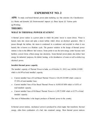
  • 6. SCHEMATIC DIAGRAM OF THERMAL POWER PLANT Fig. Typical diagram of a coal-fired thermal power station 1. Cooling tower 10. Steam Control valve 19. Superheater 2. Cooling water pump 11. High pressure steam turbine 20. Forced draught (draft) fan 3. transmission line (3-phase) 12. Deaerator 21. Reheater 4. Step-up transformer (3-phase) 13. Feedwater heater 22. Combustion air intake 5. Electrical generator (3-phase) 14. Coal conveyor 23. Economiser 6. Low pressure steam turbine 15. Coal hopper 24. Air preheater 7. Condensate pump 16. Coal pulverizer 25. Precipitator 8. Surface condenser 17. Boiler steam drum 26. Induced draught (draft) fan 9. Intermediate pressure steam turbine 18. Bottom ash hopper 27. Flue gas stack
  • 7. MAIN AND AUXILIARY EQUIPMENTS- Coal handling plant • The function of coal handling plant is automatic feeding of coal to the boiler furnace. • A thermal power plant burns enormous amounts of coal. • A 200MW plant may require around 2000 tons of coal daily Pulverizing plant In modern thermal power plant, coal is pulverised i.e. ground to dust like size and carried to the furnace in a stream of hot air. Pulverizing is a means of exposing a large surface area to the action of oxygen and consequently helping combustion. Pulverizing mills are further classified as: 1. Contact mill 2. Ball mill 3. Impact mill Draft system • The circulation of air is caused by a difference in pressure, known as Draft. • Draft is a differential pressure b/w atmosphere and inside the boiler. • It is necessary to cause the flow of gases through boiler setting • It may be – 1. Natural draft 2. Mechanical draft Boiler • A boiler or steam generator is a closed vessel in which water under pressure, is converted into steam. • It is one of the major components of a thermal power plant
  • 8. • Always designed to absorb maximum amount of heat released in the process of combustion Boilers are of two types- 1. Fire tube boiler 2. Water tube boiler Superheater and reheater Superheater: Superheater is a component of a steam-generating unit in which steam, after it has left the boiler drum, is heated above its saturation temperature. The amount of superheat added to the steam is influenced by the location, arrangement, and amount of super heater surface installed, as well as the rating of the boiler. The super heater may consist of one or more stages of tube banks arranged to effectively transfer heat from the products of combustion. Super heaters are classified as convection, radiant or combination of these. Reheater: Some of the heat of superheated steam is used to rotate the turbine where it loses some of its energy. Reheater is also steam boiler component in which heat is added to this
  • 9. intermediate-pressure steam, which has given up some of its energy in expansion through the high-pressure turbine. The steam after reheating is used to rotate the second steam turbine where the heat is converted to mechanical energy. This mechanical energy is used to run the alternator, which is coupled to turbine, there by generating electrical energy. Steam turbine A steam turbine converts heat energy of steam into mechanical energy and drives the generator. It uses the principle that steam when issuing from a small opening attains a high velocity. This velocity attained during expansion depends on the initial and final heat content of the steam. This difference b/w initial and final heat content represents the heat energy converted into kinetic energy. These are of two types:-  Impulse turbine  Reaction turbine Ash handling plant  The percentage of ash in coal varies from 5% in good quality coal to about 40% in poor quality coal  Power plants generally use poor quality of coal , thus amount of ash produced by it is pretty large  A modern 2000MW plant produces about 5000 tons of ash daily  The stations use some conveyor arrangement to carry ash to dump sites directly or for carrying and loading it to trucks and wagons which transport it to the site of disposal Condenser Steam after rotating steam turbine comes to condenser. Condenser refers here to the shell and tube heat exchanger (or surface condenser) installed at the outlet of every steam turbine in Thermal power stations of utility companies generally.  These condensers are heat exchangers which convert steam from its gaseous to its liquid state, also known as phase transition.
  • 10.  In so doing, the latent heat of steam is given out inside the condenser. Where water is in short supply an air cooled condenser is often used.  An air cooled condenser is however significantly more expensive and cannot achieve as low a steam turbine backpressure (and therefore less efficient) as a surface condenser. The purpose is to condense the outlet (or exhaust) steam from steam turbine to obtain maximum efficiency and also to get the condensed steam in the form of pure water, otherwise known as condensate, back to steam generator or (boiler) as boiler feed water. Cooling towers and ponds  A condenser needs huge quantity of water to condense the steam.  Typically a 2000MW plant needs about 1500MGallon of water.  Most plants use a closed cooling system where warm water coming from condenser is cooled and reused  Small plants use spray ponds and medium and large plants use cooling towers.  Cooling tower is a steel or concrete hyperbolic structure having a reservoir at the base for storage of cooled water
  • 11.  Height of the cooling tower may be 150 m or so and diameter at the base is 150 m Feed water heater Advantages of heating water before feeding back to the boiler:- a) Feed water heating improves overall plant efficiency. b) The dissolved oxygen and carbon dioxide which would otherwise cause boiler corrosion are removed in feed water heater c) Thermal stresses due to cold water entering the boiler drum are avoided. d) Quantity of steam produced by the boiler is increased. Some other impurities carried by the steam and condensate, due to corrosion of boiler and condenser are precipitated outside the boiler Economizer Flue gases coming out of the boiler carry lot of heat. An economizer extracts a part of this heat from flue gases and uses it for heating feed water. This use of economizer results in saving coal consumption and higher boiler efficiency
  • 12. Air preheater After flue gases leave economizer, some further heat can be extracted from them and used to heat incoming heat. Cooling of flue gases by 20 degree centigrade increases the plant efficiency by 1%. Air preheaters may be of three types  Plate type  Tubular type  Regenerative type WORKING OF THERMAL POWER PLANT Feed water heater A feed water heater is a power plant component used to pre-heat water delivered to a steam generating boiler. Preheating the feed water reduces the irreversibility involved in steam generation and therefore improves the thermodynamic efficiency of the system. This reduces plant operating costs and also helps to avoid thermal shock to the boiler metal when the feed water is introduced back into the steam cycle. Boiler A boiler is a closed vessel in which water or other fluid is heated. The heated or vaporized fluid exits the boiler for use in various processes or heating applications. Steam condensing The condenser condenses the steam from the exhaust of the turbine into liquid to allow it to be pumped. If the condenser can be made cooler, the pressure of the exhaust steam is reduced and efficiency of the cycle increases. Electrical Generator In electricity generation, an electric generator is a device that converts mechanical energy to electrical energy. Steam Turbine
  • 13. A steam turbine is a mechanical device that extracts thermal energy from pressurized steam, and converts it into rotary motion. Efficiency: The energy efficiency of a conventional thermal power station, considered as salable energy as a percent of the heating value of the fuel consumed, is typically 33% to 48%. This efficiency is limited as all heat engines are governed by the laws of thermodynamics. The rest of the energy must leave the plant in the form of heat. This waste heat can go through a condenser and be disposed of with cooling water or in cooling towers. If the waste heat is instead utilized for district heating, it is called co-generation. Planning of Power Plant involves decision on two basic parameters: 1. Total power output to be installed (e.g. 1000 MW)
  • 14. Installed capacity is determined from: • Estimated Demand: - Before setting up a power plant, we need to critically analyze demand which gives us the idea to determine capacity which needs to be installed. The installation capacity should match the demand and hence estimation of demand is the critical fact while setting up a power plant. • Growth of Demand anticipated: - While determining demand, future prospects needs to be considered so that the return on capital would be maximized and future demand could be met easily. • Reserve Capacity required: - Considering the various type of demand in a market how much reserve capacity is required to be installed is determined and hence this will help in determining installation capacity. 2. Size of generating units (e.g. 4 units of 250 MW each) Size of the generating units will depend on: • Variation of Load (Load Curve):- During the different hour of the day and in various seasons the demand varies, so the load curves. Now the number of units has to be determined to run the operations optimally and meeting the requirement daily. • Minimum start-up and shut down periods of the units • Maintenance programme planned ENVIRONMENTAL IMPACTS OF COAL BASED THERMAL POWER PLANT Impact of Thermal PowerPlant on Water Source Water Intensive  New thermal power plant of 500 MW installed capacity requires – around 14 Million m3 of water per annum.  High impact on river & ground water
  • 15.  Water demand for the once-through system is 30 to 50 times that of a closed Cycle system.  Largest emitter of mercury  Typical power plant emits 90 % of its mercury into the air and 10 percent on land  On an average 65 tonnes of mercury released in the atmosphere by Indian Thermal power plant.  Potential source of water pollution  Cooling Tower Blow Down, Boiler Blow Down, Demineralization (DM)  Plant Effluent, Coal Handling Plant Dust Suppression, Ash handling (Leachate of heavy metal (ash pond) contaminate groundwater), Effluent from oil handling and transformer areas, Power House and Turbine Area  Effluent, Domestic waste water Air pollution due to thermal power plants  Air Pollution from point source: Particulates matter, Gaseous emission - Sulphur dioxide, oxides of nitrogen, carbon monoxide, carbon dioxide, Hydrocarbon.  Air Pollution from non-point source: Transportation of coal, Loading/unloading of fuel, Coal storage yard, Fly ash Handling & Transportation., Coal storage yard