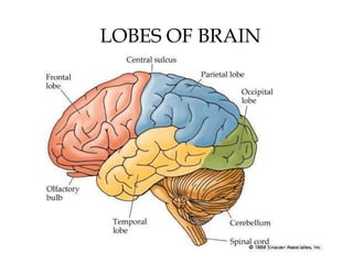
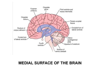
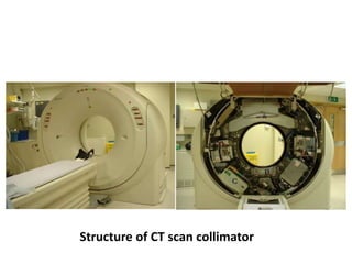
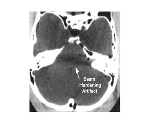
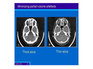
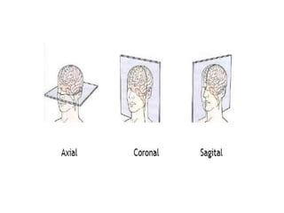
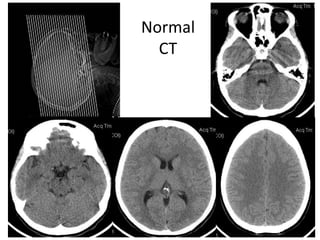
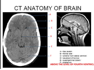
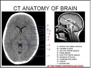
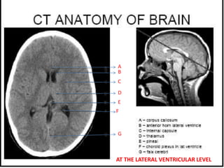
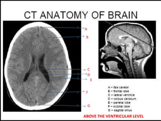
RADIOLOGICAL ANATOMY OF
NORMAL CT BRAIN
DR. PIYUSH OJHA
DM RESIDENT
DEPARTMENT OF NEUROLOGY
GOVT MEDICAL COLLEGE, KOTA
LOBES OF BRAIN
MEDIAL SURFACE OF THE BRAIN
CT History
SIR GODFREY N. HOUNSFIELD
• 1979 Nobel Laureate
in Medicine
COMPUTED TOMOGRAPHY (CT)
• Also known as Computer Assisted Tomography (CAT)
• The term Tomography refers to a process for
generating 2D image slices of an examined organ of
three dimensions (3D).
• Based on differential absorption of X- ray by various
tissues.
Structure of CT scan collimator
TECHNIQUE
• Patient is placed on the CT
table in a supine position
and the tube rotates
around the patient in the
gantry.
• To prevent unnecessary
irradiation of the orbits,
Head CTs are performed
at an angle parallel to the
base of the skull.
• Slice thickness may vary, but in general, it is
between 5 and 10 mm for a routine Head CT.
• Intravenous contrast is not routinely used, but
may be useful for evaluation of tumors,
cerebral infections.
• The degree of x-ray absorption by various tissues is
expressed and displayed as shades of gray in the CT
image.
• Darker shades correspond to lesser attenuation.
• The shades of gray correspond to a number on an
arbitrary linear scale, expressed as Hounsefield Units
(HU). (-1000 to +3000)
• WINDOWING- changing the settings to preferentially
display tissues of interest in image. Eg. Bone window
in cases of craniofacial trauma.
Pure water has an HU value of ‘0’.
DESCRIPTION Approx. HU DENSITY
Calcium > 1000 Hyperdense
Acute blood 60-80 Hyperdense
Grey matter 38 (32-42) Hyperdense
(light grey)
White matter 30 (22-32) Hyperdense
(dark grey)
CSF 0-10 ISODENSE
Fat -50 to - 80 Hypodense
Air - 1000 Hypodense
Low density High density
CSF Bone
Fluid (Edema) Calcification
Air Blood
Fat Contrast
Metallic Foreign
Bodies
CT ARTIFACTS
Artifacts are distortions or errors in the
image that are unrelated to the object
scanned .
Most common artifacts in CT are
• Motion artifacts
• Streak artifacts
• Beam hardening artifacts
• Partial volume averaging artifacts
• Ring artifacts
MOTION ARTIFACT
STREAK ARTIFACTS
Cause: Presence and
movements of objects of very
high density(contrast media,
metallic implants,surgical
clips)
Appearance: Streaks
REMEDY:-
•Remove the offending object
if possible.
RING ARTIFACT DUE TO DEFECT IN DETECTOR
SYSTEM OF THE MACHINE
CT Scan
• Advantages –
– Easy availabilty
– Fast
– Better for bone and acute blood,lesions of skull
base and calvarium
– Calcification
– Less limited by patient factors
• Disadvantages-
– high radiation
– poor visualisation of posterior fossa lesions
Normal
CT
Systemic Approach to Head CT & MRI
Interpretation
• Symmetry – Compare left and right side of the cranium
• Midline – Look for midline shift
• Cross-sectional anatomy – Review anatomical landmark
for each section.
– Brain tissue : gray matter, white matter , intracerebral
lesions
– CSF space : ventricle (dilated or not)
– Skull and soft tissue : scalp swelling, fractures, sinuses,
orbit
• Subdural windows : Look for blood collection adjacent to
the skull
• Bone windows : Skull, orbit and sinuses, intracranial air
Normal CT of Brain
• Ventricles are normal sized,
the grey versus white
distinction is clear.
• Midline is straight.
• Sulci are symmetrical on
bothsides.
• Skull is intact with no
scalp edema.
1 day 1 year 2 years
AXIAL SECTIONS OF CT HEAD
POSTERIOR FOSSA CUTS
• Above the Foramen Magnum Level
• level of the Fourth Ventricle
• Above the Fourth Ventricular Level
• Tentorial Cuts
Supratentorial Sections :
• third ventricular level
• lateral ventricular level
• above the level of Lateral Ventricle
A
B
C
D
E
F
G
ABOVE THE LEVEL OF FORAMEN MAGNUM
A
B
C
D
E
F
G
AT THE LEVEL OF FOURTH VENTRICLE
A
B
C
D
E
F
ABOVE THE LEVEL OF FOURTH VENTRICLE
A
B
C
D
E
F
G
H
I
AT THE THIRD VENTRICULAR LEVEL
A
B
C
D
E
F
G
AT THE LATERAL VENTRICULAR LEVEL
B
A
C
D
E
F
G
ABOVE THE VENTRICULAR LEVEL
A
B
C
D
ABOVE THE VENTRICULAR LEVEL
Physiologic Calcification

Normal CT BRAIN

  • 1.
    RADIOLOGICAL ANATOMY OF NORMALCT BRAIN DR. PIYUSH OJHA DM RESIDENT DEPARTMENT OF NEUROLOGY GOVT MEDICAL COLLEGE, KOTA
  • 2.
  • 3.
  • 4.
    CT History SIR GODFREYN. HOUNSFIELD • 1979 Nobel Laureate in Medicine
  • 5.
    COMPUTED TOMOGRAPHY (CT) •Also known as Computer Assisted Tomography (CAT) • The term Tomography refers to a process for generating 2D image slices of an examined organ of three dimensions (3D). • Based on differential absorption of X- ray by various tissues.
  • 6.
    Structure of CTscan collimator
  • 7.
    TECHNIQUE • Patient isplaced on the CT table in a supine position and the tube rotates around the patient in the gantry. • To prevent unnecessary irradiation of the orbits, Head CTs are performed at an angle parallel to the base of the skull.
  • 8.
    • Slice thicknessmay vary, but in general, it is between 5 and 10 mm for a routine Head CT. • Intravenous contrast is not routinely used, but may be useful for evaluation of tumors, cerebral infections.
  • 9.
    • The degreeof x-ray absorption by various tissues is expressed and displayed as shades of gray in the CT image. • Darker shades correspond to lesser attenuation. • The shades of gray correspond to a number on an arbitrary linear scale, expressed as Hounsefield Units (HU). (-1000 to +3000) • WINDOWING- changing the settings to preferentially display tissues of interest in image. Eg. Bone window in cases of craniofacial trauma.
  • 10.
    Pure water hasan HU value of ‘0’. DESCRIPTION Approx. HU DENSITY Calcium > 1000 Hyperdense Acute blood 60-80 Hyperdense Grey matter 38 (32-42) Hyperdense (light grey) White matter 30 (22-32) Hyperdense (dark grey) CSF 0-10 ISODENSE Fat -50 to - 80 Hypodense Air - 1000 Hypodense
  • 11.
    Low density Highdensity CSF Bone Fluid (Edema) Calcification Air Blood Fat Contrast Metallic Foreign Bodies
  • 13.
    CT ARTIFACTS Artifacts aredistortions or errors in the image that are unrelated to the object scanned . Most common artifacts in CT are • Motion artifacts • Streak artifacts • Beam hardening artifacts • Partial volume averaging artifacts • Ring artifacts
  • 14.
  • 15.
    STREAK ARTIFACTS Cause: Presenceand movements of objects of very high density(contrast media, metallic implants,surgical clips) Appearance: Streaks REMEDY:- •Remove the offending object if possible.
  • 18.
    RING ARTIFACT DUETO DEFECT IN DETECTOR SYSTEM OF THE MACHINE
  • 19.
    CT Scan • Advantages– – Easy availabilty – Fast – Better for bone and acute blood,lesions of skull base and calvarium – Calcification – Less limited by patient factors • Disadvantages- – high radiation – poor visualisation of posterior fossa lesions
  • 21.
  • 22.
    Systemic Approach toHead CT & MRI Interpretation • Symmetry – Compare left and right side of the cranium • Midline – Look for midline shift • Cross-sectional anatomy – Review anatomical landmark for each section. – Brain tissue : gray matter, white matter , intracerebral lesions – CSF space : ventricle (dilated or not) – Skull and soft tissue : scalp swelling, fractures, sinuses, orbit • Subdural windows : Look for blood collection adjacent to the skull • Bone windows : Skull, orbit and sinuses, intracranial air
  • 23.
    Normal CT ofBrain • Ventricles are normal sized, the grey versus white distinction is clear. • Midline is straight. • Sulci are symmetrical on bothsides. • Skull is intact with no scalp edema.
  • 24.
    1 day 1year 2 years
  • 25.
    AXIAL SECTIONS OFCT HEAD POSTERIOR FOSSA CUTS • Above the Foramen Magnum Level • level of the Fourth Ventricle • Above the Fourth Ventricular Level • Tentorial Cuts Supratentorial Sections : • third ventricular level • lateral ventricular level • above the level of Lateral Ventricle
  • 26.
  • 27.
    A B C D E F G AT THE LEVELOF FOURTH VENTRICLE
  • 28.
    A B C D E F ABOVE THE LEVELOF FOURTH VENTRICLE
  • 29.
  • 30.
  • 31.
  • 32.
  • 33.