
Recommended
More Related Content
What's hot
What's hot (20)
Similar to AB MACHINERY AND MECHANIZATION
Similar to AB MACHINERY AND MECHANIZATION (20)
Recently uploaded
Recently uploaded (20)
AB MACHINERY AND MECHANIZATION
- 1. LABO CAMPUS - COLLEGE OF AGRICULTURE AND NATURAL RESOURCES LESSON 1 ON AB MACHINERY AND MECHANIZATION (AB 125) A. INTRODUCTION AND HISTORY PHILIPPINE AGRICULTURAL AND ENGINEERING STANDARDS (PAES) The centerpiece program of the government in poverty alleviation, food security, rationale use of resources, global competitiveness, and sustainable development is the Agriculture and Fisheries Modernization Act (AFMA). A close examination of the major tenets of AFMA points to a very heavy reliance on the support from the field of agricultural engineering. Overall, AFMA places high priority on the following agricultural engineering technologies: irrigation, postharvest, structures, rural electrification, mechanization, alternative energy, domestic water supply, farm roads and bridges. In responding to the challenge, sound agricultural engineering principles and practices are required in the planning, design, construction, operation and optimization of agricultural engineering technologies, systems and services. At the onset, the availability of Philippine Agricultural Engineering Standards (PAES) is required to ensure to a great extent the success of agricultural engineering projects in terms of technical performance. Development of standards for agricultural engineering in the Philippines started in the late 1970’s with the Bureau of Product Standards of the Department of Trade and Industry creating the Technical Committee on Machinery for agriculture and forestry (BPS/TC56). Later, BPS/ TC56 was replaced by TC 19 and the Agricultural Machinery Testing and Evaluation Center (AMTEC) was designated as its official writing office. Pursuant to Articles 5 and 6, Chapter I, Title II of Republic Act No. 7394, otherwise known as the Consumer Act of the Philippines, standards development and its implementation was identified to three agencies: Department of Agriculture (agricultural products), Department of
- 2. Health (drugs, cosmetics, devices and substances) and Department of Trade and Industry (other products not covered by the two agencies). It is stated in Rule 59.1 of the Implementing Rules and Regulations of Republic Act No. 8435, otherwise known as Agriculture and Fisheries Modernization Act of 1997 or AFMA that AMTEC may be designated by the Department of Agriculture to issue standards for agriculture and fisheries machinery. On 30 May 2001, the DA secretary issued Administrative Order No. 11 series of 2001 stating that standard specifications and test procedures of agricultural machinery shall be developed. AMTEC, in partnership with the PSAE and concerned DA agencies, shall be charged with formulation and development of the official agriculture and fisheries machinery standards. Such standards, to be known as the “Philippine Standards for Agriculture and Fisheries Machinery” shall be subjected to public hearings by the NAFC through its Agricultural and Fisheries Mechanization Committee (AFMeC), prior to its approval by the Secretary of Agriculture. The University of the Philippines Los Baños (UPLB), Bureau of Agricultural Research (BAR), Bureau of Postharvest Research and Extension (BPRE), Philippine Council for Agriculture, Forestry and Natural Resources Research and Development (PCARRD), Professional Regulation Commission – Board of Agricultural Engineers (PRC-BOAE) and the Philippine Society of Agricultural Engineers (PSAE), upon realization of the dire need for standards, initiated projects that will develop a set of Philippine National Standards for Agricultural Engineering to contribute to agricultural modernization, national development and global competitiveness. However, standards development has now been mandated to the DA Bureau of Agriculture and Fisheries Standards (BAFS) in compliance with the Agricultural and Fisheries Mechanization (AFMech) Law of 2013. Section 27 of the said law states that, as the premier testing center, AMTEC shall assist BAFS in the formulation of quality, safety, and performance standards of agricultural and fisheries machinery and of accreditation guideline for testing centers. WALKING-TYPE AGRICULTURAL TRACTOR SPECIFICATIONS PHILIPPINEAGRICULTURALENGINEERINGSTANDARD PAES 109 :2000
- 3. Foreword The formulation of this Standard was initiated by the Agricultural Machinery Testing and Evaluation Center (AMTEC) under the project entitled "Enhancing the Implementation of AFMA Through Improved Agricultural Engineering Standards” which was funded by the Bureau of Agricultural Research (BAR) of the Department of Agriculture (DA). This revised standard was reviewed by the Technical Committee for Study 1- Development of Standards for Agricultural Production Machinery and was circulated to various private and government agencies/organizations concerned for their comments and reactions. This standard was presented to the Philippine Society of Agricultural Engineers (PSAE) and subjected to a public hearing organized by the National Agriculture and Fisheries Council (NAFC). The comments and reactions received during the presentation and public hearing were taken into consideration in the finalization of thisstandard. This standard has been formulated in accordance with PNS 01:Part 4:1998 - Rules for the Structure and Drafting of Philippine National Standards. In the preparation of this standard, the following documents/publications were considered: AMTEC Test Reports on walking-type agricultural tractor Republic Act No. 7394 otherwise known as “The Consumer Act of the Philippines” enacted on July 22, 1991. PHILIPPINEAGRICULTURALENGINEERINGSTANDARD PAES 109 : 2000 Agricultural Machinery – Walking-type Agricultural Tractor – Specifications Part 1 :Pull-type 1 Scope This standard specifies the requirements for walking-type agricultural tractor which is classified as pull-type. This includes tractors with chain and sprocket transmission system, gear transmission system and combination thereof. 2 References The following normative documents contain provisions, which, through reference in this text, constitute provisions of this Standard:
- 4. PAES 102:2000, Agricultural Machinery – Operator’s Manual – Content and Presentation PAES 103:2000, Agricultural Machinery – Method ofSampling. PAES 107:2000, Agricultural Machinery – Hitch for Walking-Type Agricultural Tractor – Specifications. PAES 108:2000, Agricultural Machinery – Hexagonal Axle and Hub for Walking Type Agricultural Tractor –Specifications. PAES 111:2000, Agricultural Machinery – Walking-Type Agricultural Tractor – Methods of Test. 3 Definitions For the purpose of this standard, the following definitions shall apply: 3.1 walking-type agricultural tractor hand tractor pedestrian tractor self-propelled machine having a single axle designed primarily to pull and propel trailed or mounted agricultural implements and machinery 3.2 pull type traction type capable of pulling various kinds of implements 4 Construction The basic construction and components of the tractor is shown in Figure 1.
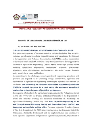
- 5. PAES 109 : 2000 A-89 Main clutch lever Throttle lever Hand grip Figure 1 – Components of Walking-type Agricultural Tractor (Pull-type) 5 Materials of Construction 5.1 The tractor shall be generally made of steel bars and sheet metals. 5.2 At least ISO chain number 10A-1 (ANSI chain number 50) shall be used for the chain and sprocket transmission system. 5.3 The handle bar shall be made of Black Iron (BI) pipe (schedule 40) with a minimum diameter of 25 mm. 6 Controls 6.1 Throttle Lever 6.1.1 This shall be accessible to the operator’s right-hand side of the handle bar. 6.1.2 Types of throttle levers 6.1.2.1 Vertical type Engine Engine pulley Belt guard Input shaft pulley Handle bar Handle bar adjustment Engine mounting frame Idler pulley Hitch Assembly Transmission assembly Mud guard Stand assembly Axle Cage wheel
- 6. PAES 109 : 2000 A-90 For this type, the throttle lever is pushed forward to increase engine speed and pulled rearward to decrease engine speed. 6.1.2.2 Horizontal Type For this type, the throttle lever is pulled to the left to increase engine speed and to the right to decrease engine speed. 6.2 Main Clutch Lever 6.2.1 This shall be accessible to the operator’s-left hand side of the handle bar. 6.2.2 In the case of a vertical lever, the lever shall be pushed forward to start the forward motion of the tractor and shall be pulled rearward to stop the tractor. An over- center linkage shall lock the lever in the forward engagedposition. 6.2.3 In the case of a horizontal lever, the lever shall be pushed upward to start the forward motion of the tractor and shall be pulled downward to stop the tractor. A lock shall be provided to hold the lever in the upward engagedposition. 7 Performance Requirements The tractor when tested in accordance with PAES 111 shall conform to the following requirements: 7.1 The peak transmission efficiency of the tractor shall be at least 85%. 7.2 The manufacturer’s specified minimum field capacity of the tractor shall be attained. The noise emitted by the tractor measured 50 mm away from the operator’s ear level shall not be more than 92 db (A). * 8 Other Requirements 8.1 For operator’s safety, the following shall beprovided
- 7. PAES 109 : 2000 A-91 8.1.1 Belt guard or cover 8.1.2 Mud guard 8.1.3 Rubber hand grip 8.2 Mechanisms for transmission belt adjustment shall beprovided. 8.3 Mechanism for handle bar height adjustment shall beprovided. 8.4 The hitch of the tractor shall be in accordance with the specifications of PAES 107. * Allowable noise level for six (6) hours of continuous exposure based on Occupational Safety and Health Standards, Ministry of Labor, Philippines. 1983. 8.5 The hexagonal axle of the tractor shall be in accordance with the specifications of PAES 108. 8.6 When the tractor is in transport mode, agricultural rubber tires shall be used. 9 Workmanship and Finish 9.1 The tractor shall be free from manufacturing defects that may be detrimental to its operation. 9.2 Any uncoated metallic surfaces shall be free from rust and shall be painted properly. The tractor shall be free from sharp edges and surfaces that may injure the operator.
- 8. PAES 109 : 2000 A-92 10 Warranty for Construction and Durability 10.1 Warranty against defective materials and workmanship shall be provided for parts and services except on consumable maintenance parts such as belts within six (6) months from the purchase of the tractor. 10.2 The construction shall be rigid and durable without breakdown of its major components (i.e. transmission systems, etc) within six (6) months from purchase by the first buyer. 11 Maintenance and Operation 11.1 Each tractor unit shall be provided with the following basic hand tools: three (3) pieces open wrenches; one (1) piece each of Philips and flat screw driver; and one (1) piece adjustable wrench. 11.2 An operator’s manual, which conforms to PAES 102, shall be provided. 12 Sampling The tractor shall be sampled for testing in accordance with PAES 103. 13 Testing The sampled tractor shall be tested in accordance with PAES 111. 14 Marking and Labeling Each tractor shall be marked with the following information using a plate, stencil or by directly punching it at the most conspicuous place: 14.1 Registered Trademark of the Manufacturer 14.2 Brand
- 9. PAES 109 : 2000 A-93 14.3 Model 14.4 Serial number 14.5 Name and address of the manufacturer 14.6 Name and address of the importer, if imported(optional) 14.7 Country of manufacture (if imported) / “Made in the Philippines” (if manufactured in the Philippines) 14.8 Power requirement, kW 14.9 Safety/precautionary markings WALKING-TYPE AGRICULTURAL TRACTOR METHODS OF TEST PHILIPPINEAGRICULTURALENGINEERINGSTANDARD PAES 111 : 2000 Foreword This standard is a revision of the Standards Administrative Order (SAO) series of 1980 – “Standardization of Procedures of Inspection and Test for Walking-type Agricultural Tractor”. The pursuance of this standard was initiated by the Agricultural Machinery Testing and Evaluation Center (AMTEC) under the project entitled “Enhancing the Implementation of AFMA Through Improved Agricultural Engineering Standards” which was funded by the Bureau of Agricultural Research (BAR) of the Department of Agriculture (DA). This standard was reviewed by the Technical Committee for Study 1- Development of Standards for Agricultural Production Machinery and was circulated to various private and government agencies/organizations concerned for their comments and reactions. This standard was presented to the Philippine Society of Agricultural Engineers (PSAE) and subjected to a public hearing organized by the National Agriculture and Fisheries Council (NAFC). The comments and reactions received during the presentation and public hearing were taken into consideration in the finalization of this standard.
- 10. PAES 109 : 2000 A-94 This standard has been technically revised in accordance with PNS 01:Part 4:1998 - Rules for the Structure and Drafting of Philippine National Standards. The main changes are listed below: 15 title of the standard has been modified in conformity to the format of International Standard; 16 the scope was delineated thereby indicating the aspects covered and the limits of applicability; and 17 items to be included in the test report were enumerated based on the actual test report submitted by AMTEC. In the preparation of this standard, reference was made to the actual testing procedure for Walking-type Agricultural Tractor. All annexes in this standard are normative. PHILIPPINEAGRICULTURALENGINEERINGSTANDARD PAES 111 : 2000 Agricultural Machinery – Walking-Type Agricultural Tractor – Methods of Test 1 Scope This standard specifies the methods of test and inspection for walking-type agricultural tractor, which can also be temporarily used for riding by the use of attachments. Specifically, it shall be used to: 1.1 verify the requirements specified in PAES 109 and PAES 110 and the specifications submitted by the manufacturer; 1.2 determine the field performance of the machine 1.3 evaluate the ease of handling and safety features 1.4 determine the laboratory performance of the machine
- 11. PAES 109 : 2000 A-95 1.4.1 transmission efficiency 1.4.2 varying load performance 1.4.3 continuous running 1.5 prepare a report on the results of the tests 2 References The following documents contain provisions, which, through reference in this text, constitute provisions of this Standard: PAES 109:2000, Agricultural Machinery – Walking-Type Agricultural Tractor – Specifications – Part 1: Pull-type PAES 110:2001, Agricultural Machinery – Walking-Type Agricultural Tractor – Specifications – Part 2: Rotary-tilling type 3 Definitions For the purpose of this standard, the definitions given in PAES 109 and PAES 110 and the following shall apply: 3.1 applicable work range of operations that could be performed by the machine as specified by the manufacturer 3.2 ground clearance distance between the supporting surface and the lowest point of the tractor
- 12. PAES 111 : 2000 A-95 3.3 overall height distance between the horizontal supporting surface and the horizontal plane touching the uppermost part of the tractor NOTE All parts of the tractor, in particular, fixed components projecting upwards are contained between these two planes. 3.4 overall length distance between two vertical planes at right angles to the median plane of the tractor and touching its front and rear extremities NOTE All parts of the tractor, in particular, components projecting at the front and at the rear are contained between these two planes. Where an adjustment of components is possible, it shall be set at minimum length. 3.5 overall width distance between two vertical planes parallel to the median plane of the tractor, each plane touching the outer-most point of the tractor on its respective side and with wheels set for minimum track NOTE All parts of the tractor, in particular, fixed components projecting laterally are contained between these two planes. 3.6 slip ratio of the difference between the speed of pulley or belt and wheels or track with load, to the speed without load 3.6.1 Belt slip of pulley is determined by the followingformula:
- 13. PAES 111 : 2000 A-96 where: n0 is the revolution/minute of the driven pulley without load, rpm n1 is the revolution/minute of the driven pulley with load, rpm 3.6.2 Slip of driving wheels or tracks is determined by the following formula: 3.7 where: N0 is the sum of the revolutions of all driving wheels for the same distance without load, rpm N1 is the sum of the revolutions of all driving wheels for a given distance with load, rpm tractor weight total weight of the machine excluding ballast and implements with the fuel tank filled to 80 percent capacity and with normal amount of cooling water and lubricating oil (if engine is integrated with the tractor) and with specified wheels. 3.8 walking-type agricultural tractor self-propelled machine having a single axle designed primarily to pull and propel trailed or mounted agricultural implements and machinery 4 General Conditions for Test and Inspection 4.1 Role of the manufacturer/dealer The manufacturer/dealer shall submit to the official testing agency the specifications and other relevant information on the walking-type agricultural tractor. An official representative shall be appointed to conduct minor repair, adjust and witness the test. It shall be the duty of the representative to make all decisions on matters of adjustment and preparation of the machine for testing. The manufacturer/dealer shall abide by the terms and conditions set forth by the official testing agency.
- 14. PAES 111 : 2000 A-97 4.2 Running-in and preliminary adjustment Before the start of the test, the tractor should have undergone a breaking-in period. Before the field performance test, the tractor shall be operated at the test site to make the necessary adjustments as per manufacturer's recommendations. No adjustments shall be permitted during the test. 4.3 Test instruments and other needs The suggested list of minimum field and laboratory test equipment and materials needed to carry out the tractor test is shown in Annex A. These instruments should be calibrated regularly. These instruments shall be physically checked for operation and shall be cleaned before and after each test. A checklist of instruments and materials shall be prepared to be used before departure to and from the testing area. 4.2 Suspension of test If during the test run, the machine malfunctions so as to affect the machine's performance, the test may be suspended with the concurrence of the official testing agency and the manufacturer’s representative. If it is the engine that fails, it can be changed with an identical unit (if the engine is not integrated with the tractor). 5 Tests and Inspection 5.1 Verification of Manufacturer’s Technical Data andInformation 5.1.1 This investigation is carried out to verify that the mechanism, main dimensions, weight and attachments of the tractor conform to the list of technical data and information submitted by the manufacturer. (see Annex A) 5.1.2 A plain and level platform shall be used for this investigation. 5.1.3 The items to be inspected and verified are given in Annex B. 5.2 Field Performance Tests 5.2.1 These are carried out to test the field performance of operations applicable to the tractor to be tested. For wetland test field, the field shall be soaked for at least twenty- four (24) hours.
- 15. PAES 111 : 2000 A-98 5.2.2 The tests shall be carried out on a dry/wet field where the soil type, dimensions, soil moisture content/depth of water, soil resistance, shape and other conditions are to be recorded.
- 16. PAES 111 : 2000 A-99 5.2.3 The kinds of field performance tests shall be thefollowing: 5.2.3.1 Plowing This shall be done for fields of not less than 500 m2 and shall be rectangular with sides in the ratio of 2:1 as far as possible with three replications using circuitous method of plowing operation. Plowing depth shall be 100 mm + 10 mm. The field may be irrigated or flooded depending on the condition. 5.2.3.2 Rotary tilling This shall be done for field of not less than 500 m2 and shall be rectangular with the sides in the ratio of 2:1 as far as possible with three replications. Tilling depth shall be 100 mm to 120 mm. The field may be irrigated or flooded depending on the condition. 5.2.3.3 Harrowing This shall be carried out after plowing test on the same field under dry/flooded conditions. 5.2.4 The items to be measured, investigated and recorded during the field performance tests are given in Annex C. 5.3 Laboratory Performance Tests 5.3.1 Transmission efficiency 5.3.1.1 This is carried out to determine the efficiency of the transmission system of the tractor, using an electric motor that is either calibrated or coupled with a torque transducer. 5.3.1.2 The tractor on test, without its wheels, shall be fixed on the test frame. Brake load is applied on the wheel axle and/or rotary tilling shaft by a dynamometer.
- 17. PAES 111 : 2000 A-100 5.3.1.3 Power is transmitted from the motor output shaft to the input shaft (first shaft) of transmission box in the same manner as those from engine to that of tractor, for instance, V- belt. The diameter of the pulley on the output shaft of the electric motor is computed so that speed of input shaft at rated speed of electric motor is the same as that of rated engine speed. This test will not be applied to a tractor which engine and transmission box are directly coupled. 5.3.1.4 Brake load shall be applied until the computed axle power or tilling shaft power reaches the maximum value. 5.3.1.5 Items to be measured and recorded are given in AnnexD. 5.3.2 Varying load performance 5.3.2.1 This is carried out to determine the performance of the tractor under different loadings applied to the wheel axle or rotary tilling shaft. 5.3.2.2 The tractor on test, with its engine but without its wheels, shall be fixed on the test frame. 5.3.2.3 The engine shall be set at its rated speed and brake load shall be applied on the wheel axle or rotary tilling shaft by a dynamometer at an increment of 5-kg load until the engine stalls. 5.3.2.4 The load, speed of engine output shaft, transmission input shaft and axle, fuel consumption and temperature of exhaust gas, transmission oil, atmospheric dry bulb and wet bulb temperatures shall be measured simultaneously every 3 minutes at each applied brake load. 5.3.2.5 Items to be measured and recorded are given in AnnexE. 5.3.3 Continuous-running test 5.3.3.1 This is carried out to evaluate the operating performance and to find out any abnormality or trouble under the continuous running condition of the tracto
- 18. PAES 111 : 2000 A-101 5.3.3.2 The tractor on test, with its engine but without its wheels, shall be fixed on the test frame. Brake load is applied on the wheel axle or rotary tilling shaft by a dynamometer. 5.3.3.3 The engine shall be set at its rated speed and a brake load equivalent to the maximum axle/rotary tilling shaft power taken during the varying load performance test shall be applied on the wheel axle/rotary tilling shaft. 5.3.3.4 The load, speed of engine, transmission input shaft and axle/rotary tilling shaft, fuel consumption, and temperature of exhaust gas and transmission oil shall be measured simultaneously every thirty (30) minutes. 5.3.3.5 The testing methods for each type of walking-type agricultural tractor shall be as follows: 5.3.3.5.1 Pull type 5.3.3.5.1.1 A brake load shall be applied on the wheelaxle. 5.3.3.5.1.2 The change-gear position shall be at the largest-ratio-reduction within the plowing speed range mentioned in the specifications. 5.3.3.5.1.3 The duration of continuous running test shall be 5hours. 5.3.3.5.2 Tilling type 5.3.3.5.2.1 A brake load shall be applied on the rotary tillingshaft. 5.3.3.5.2.2 The change-gear position shall be at the largest-ratio-reduction within the tilling speed range mentioned in the specifications. 5.3.3.5.2.3 The wheel axle shall be driven with noload. 5.3.3.5.2.4 The duration of continuous running test shall be five (5) hours.
- 19. PAES 111 : 2000 A-102 5.3.3.5.3 Dual-purpose type 5.3.3.5.3.1 There shall be two kinds of tests under dual-purpose type: wheel axle loading and tilling shaft loading tests. 5.3.3.5.3.2 The method of loading on wheel axles and rotary tilling shaft shall be the same as in pull type and tilling type, respectively. However, the duration of continuous running shall be for two and a half (2.5) hours in either case. 5.3.3.6 Items to be measured and recorded are given in AnnexF. 6 Data Analysis The formulas to be used during calculations and testing are given in Annex G. 7 Test Report The test report shall include the following information in the order given: 7.1 Name of testing agency 7.2 Test report number 7.3 Title 7.4 Summary 7.5 Purpose and scope of test 7.6 Methods of test 7.7 Description of the hand tractor 7.7.1 Table 1 – Hand tractor Specifications 7.8 Results of Field Test 7.8.1 Table 2 – Field Performance Test Data 7.9 Results of Laboratory Tests 7.9.1 Table 3 – Results of Varying Load PerformanceTest 7.9.2 Table 4 – Results of Continuous Running Test 7.9.3 Table 5 – Results of Transmission EfficiencyTest 7.10 Observations 7.11 Name and Signature of Test Engineers
- 20. PAES 111 : 2000 A-103 Annex A Suggested Minimum List of Field and Laboratory Test Equipment and Materials Items Quantity A1 Equipment A1.1 Field Equipment A1.1.1 Timers Range: 60 minutes: Accuracy 1/10 2 A1.1.2 Noise Level Meter Range : 30 to 130 db(A) 1 A1.1.3 Cone Penetrometer 1 A1.1.4 Steel Tape, 50 m 1 A1.1.5 Graduated Cylinder, capacity: 500 mL 1 A1.1.6 Width and Depth Gage 1 A1.1.7 Camera 1 A1.2 Laboratory Equipment A1.2.1 Load Cells, capacity:100 kg 2 A1.2.2 Strain Amplifier 1 A1.2.3 Multi-testers 2 A1.2.4 Tachometer, contact type 2 A1.2.5 Power Meter Maximum voltage and current: Vrms and 20 Arms 1 A2 Materials for Field Test A2.1 Pegs 10 A2.2 Aluminum Foil 1 A2.3 Labeling Tags 10
- 21. PAES 111 : 2000 A-104 Annex B Inspection Sheet for Walking-type Agricultural Tractor Name ofApplicant : Address : Telephone No.: Name ofDistributor : Address : Name ofManufacturer : Factory Address: GENERAL INFORMATION Brand : Model : Serial No. : Engine Serial No. : Classification (pull type, tilling type or dual purpose type) : Production date of walking-type agricultural tractor to be tested :
- 22. PAES 111 : 2000 A-105 Items to be inspected ITEMS Manufacturer's Specification Verification by Testing Agency B1 Dimensions and weight of tractor B1.1 Overall length, mm B1.2 Overall width, mm B1.3 Overall height, mm B1.4 Ground clearance, mm B1.5 Weight of tractor (without engine), kg B2 Engine B2.1 Make/Country of Manufacture B2.2 Model B2.3 Serial Number B2.4 Type B2.4.1 Stroke B2.4.1.1 Four-stroke B2.4.1.2 Two-stroke B2.4.2 Ignition B2.4.2.1 Compression ignition B2.4.2.2 Spark ignition ITEMS Manufacturer's Specification Verification by Testing Agency B2.5 Rated speed,rpm
- 23. PAES 111 : 2000 A-106 B2.6 Rated power, kW B2.7 Fuel system B2.7.1 Type of fuel B2.7.1.1 Gasoline B2.7.1.2 Diesel B2.7.2 Tank capacity, L B2.7.3 Fuel consumption, L/h B2.8 Cooling system B2.8.1 Air-cooled B2.8.2 Water-cooled B2.9 Starting system B2.9.1 Rope recoil B2.9.2 Hand cranked B2.10 Weight, kg B3 Type of clutch B3.1 Main clutch B3.2 Steering clutch (if any) B3.3 Tilling clutch (if any) B4 Power transmission system B4.1 Type B4.1.1 Chain and sprocket B4.1.2 Gears B4.2 Lubrication system B4.2.1 Splash type B4.2.2 Forced-feed B5 Engine pulley (outside diameter x no.of grooves x inside diameter, mm) B6 Input shaft pulley (outside diameter x no. of grooves x inside diameter, mm) B7 Axle, L x W, mm
- 24. PAES 111 : 2000 A-107 B8 Hexagonal hub B8.1 Thickness, mm B8.2 Length, mm B9 Type of hitch point B9.1 Type I – One-hole Hitch B9.2 Type II – Three-hole Hitch B10 Tractive Wheels B11.1 Pneumatic Tire Size B11.2 Cage Wheel Size, L x D,mm B11 Attachments B11.1 Plow B11.2 Harrow B11.3 Rotary tiller Annex C Field Performance Test Data Sheet
- 25. PAES 111 : 2000 A-108 Items to be Measured and Inspected ITEMS Trials Average 1 2 3 C1 Test Conditions C1.1 Condition of field C1.1.1 Location C1.1.2 Soil type (clay, clay loam, sandy,etc) C1.1.3 Dimensions of field C1.1.3.1 Length, m C1.1.3.2 Width, m C1.1.3.3 Area, m2 C1.1.4 Depth of water/moisture content, mm/% C1.1.5 No. of hours soaked (wet land) C1.1.6 Soil resistance, kg/cm2 C1.1.7 Spacing of stubbles, mm (rows x hills) C1.1.8 Height of stubbles, mm C1.1.9 Weed growth, no/m2 C1.2 Weather conditions C1.2.1 Temperature C1.2.1.1 Wet bulb, ºC C1.2.1.2 Dry bulb, ºC C1.2.2 Weather (sunny, cloudy, rainy, hot, cold..) C1.3 Condition of the tractor C1.3.1 Tractive device C1.3.1.1 Type
- 26. PAES 111 : 2000 A-109 C1.3.1.2 Size C1.3.2 Implement to be used C1.3.2.1 Type C1.3.2.2 Size C1.3.3 Wheel track C1.3.4 Additional weight, kg C1.3.4.1 Front-end C1.3.4.2 Wheel
- 27. PAES 111 : 2000 A-110 ITEMS Trials Average 1 2 3 C1.3.5 Gross weight, kg C1.3.6 Speed-gear positions C1.3.6.1 Main transmission C1.3.6.2 Auxiliary transmission C1.3.6.3 Belt speed-change C1.3.6.4 Rotary speed change C1.3.7 Others C2 Field Performance C2.1 Date of test C2.2 Kind of field operation C2.3 Duration of test, min C2.4 Time lost C2.4.1 Turning, min C2.4.2 Others (specify), min C2.5 Type of implement C2.6 Method of operation C2.7 Depth of cut, mm C2.8 Travelling speed, kph C2.9 Theoretical width of tillage, mm C2.10 Actual width of tillage, mm C2.11 Theoretical field capacity, ha/h C2.12 Actual field capacity, ha/h C2.13 Field efficiency, % C2.14 Fuel consumed, L C2.15 Fuel consumption, L/h C2.16 Others (specify) C3 Observations:
- 28. PAES 111 : 2000 A-111 C3.1 Ease of handling and stability of the tractor C3.2 Ease of manipulating of the operating levers C3.3 Ease of replacing and adjusting the parts C3.4 Safety features C3.5 Failure or abnormalities that may be observed on the tractor or its component parts C3.6 Others
- 29. PAES 111 : 2000 Annex D Transmission Efficiency Test Data Sheet Test Specimen : Prime Mover : Test Engineer : Trial No. : Date : Place of Test : Test Conditions 1. Air Temperature Motor Input Axle Dry Bulb, C : Wet Bulb, C: 2. Relative Humidity, % : No Load Speed,rpm : Speed Reduction Ratio: Time min Axle Load, kg Speed, rpm Belt Slippage % Axle Torque kg-m Axle Shaft Power kW Input Efficiency % Left Right Total Drive Shaft Axle Shaft Torque kg-m Speed rpm Power kW PAES 111 : 2000 A-106
- 30. PAES 111 : 2000
- 31. Annex E Varying Load Performance Test Data Sheet E.1 Wheel Axle Test Specimen : Prime Mover : Test Engineer : Test Conditions Trial No. : Date : Place of Test: 1. Air Temperature Motor Input Axle Dry Bulb, C : Wet Bulb, C: 2. Relative Humidity, % : No Load Speed,rpm : Speed Reduction Ratio: Time min Axle Load, kg Speed, rpm Belt Slippage % Axle Torque kg-m Axle Shaft Power kW Temperature, C Fuel Consumption L/h Specific Fuel Consumption g/kW-h Left Right Total Engine Shaft Drive Shaft Axle Shaft Exhaust gas Transmission oil
- 33. E.2 Rotary Tilling Shaft Test Specimen : Prime mover : Test Engineer : Trial No. : Date : Place of Test : Test Conditions 1. Air Temperature Dry Bulb, C : Wet Bulb, C: 2. Relative Humidity, % : Time Rotary Shaft Load Speed, rpm Belt Slippage Rotary Shaft Torque Rotary Shaft Power Temperature, C Fuel Consumption Specific Fuel Consumption Engine Shaft Drive Shaft Rotary Shaft Exhaust gas Transmission oil min kg % kg-m kW L/h g/kW-h PAES 111 : 2000 A-108
- 35. Annex F Continuous Running Test Data Sheet F.1 Wheel Axle Test Specimen : Prime Mover : Test Engineer : Trial No. : Date : Place of Test : Test Conditions 1. Air Temperature Motor Input Axle Dry Bulb, C : Wet Bulb, C: 2. Relative Humidity, % : No Load Speed,rpm : Speed Reduction Ratio: Time Axle Load, kg Speed, rpm Belt Slippage % Axle Torque kg-m Axle Shaft Power kW Temperature, C Fuel Consumption L/h Specific Fuel Consumption g/kW-h Left Right Total Engine Shaft Drive Shaft Axle Shaft Exhaust gas Transmission oil min PAES 111 : 2000 A-109
- 37. F.2 Rotary Tilling Shaft Test Specimen : Prime Mover : Test Engineer : Trial No. : Date : Place of Test : Test Conditions 1. Air Temperature Dry Bulb, C : Wet Bulb, C: 2. Relative Humidity, % : Time Rotary Shaft Load Speed, rpm Belt Slippage Rotary Shaft Torque Rotary Shaft Power Temperature, C Fuel Consumption Specific Fuel Consumption Engine Shaft Drive Shaft Rotary Shaft Exhaust gas Transmission oil min kg % kg-m kW L/h g/kW-h PAES 111 : 2000 A-110
- 39. PAES 111 : 2000 Annex G FormulasUsedDuringCalculations andTesting G1 Field Performance Test G1.1 Estimation of Effective Field Capacity G1.1.1 Average swath or width of cut, S, (m) S = W 2n where: W is the width of plot, m n 2 is the number of rounds is the number of trips per round G1.1.2 Total distance traveled, D, (m) D = A = 2nL S where: A = L x W where: A is the area of plot, m2 L is the length of the plot, m G1.1.3 Effective area accomplished, Ae, (m2 ) Ae = wD = 2nLw where: w is the width of plow or rotary tiller, m G1.1.3.1 If width of swath is less than the plow’s or rotary tiller’s width, the operator has passed over part of the area twice to secure better coverage, therefore: Ao = Ae - A
- 40. PAES 111 : 2000 where: Ao is the overlap (area which is plowed or rototilled twice), m2 G1.1.3.2 If the average width of swath is greater that the plow’s or rotary tiller’s width, the operator has left part of the area unplowed or unrototilled, therefore: Au = A - Ae where: Au is the unplowed or unrototilled area (area missed), m2 A-111
- 41. PAES 111 : 2000 PAES 111 : 2000 G1.1.4 Effective field capacity, efc, (m2 /h) efc = 60Ae t where: t is the time used during the operation,min G1.2 Theoretical Field Capacity, tfc, (m2 /h) tfc = we x v where: we is the effective or theoretical width of tillage, m v is the speed of operation, m/h G1.3 Field Efficiency, Feff, (%) Feff = efc tfc x 100 G1.4 Fuel Consumption, FC, (L/h) FC = V t G2 Laboratory Tests where: V is the volume of fuel consumed, L t is the total operating time, h G2.1 Axle/Rotary Shaft Torque, T, (kg-m)
- 42. PAES 111 : 2000 T = F x L where: F is the axle or rotary shaft load, kg L is the length of pony brake arm, m G2.2 Axle/Rotary Shaft Power, P, (kW) P = Ft x N 1340 where: Ft is the total axle or rotary shaft load, kg N is the speed of axle or rotary shaft, rpm G2.3 Specific Fuel Consumption, SFC, (g/kW-h) SFC = Fc x f P where: Fc is the fuel consumption, L/h f is the density of fuel, g/L P is the axle or rotary shaft power, kW Prepared by: ENGR. DAVE Y. RIEZA Instructor
- 43. PAES 111 : 2000