
Recommended
More Related Content
More from ujfjjkjskkemme
More from ujfjjkjskkemme (20)
Recently uploaded
Recently uploaded (20)
Jcb transmissions service repair manual
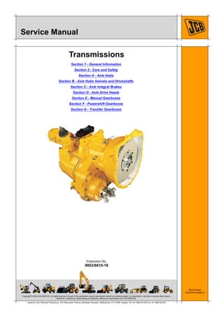
- 1. Copyright © 2004 JCB SERVICE. All rights reserved. No part of this publication may be reproduced, stored in a retrieval system, or transmitted in any form or by any other means, electronic, mechanical, photocopying or otherwise, without prior permission from JCB SERVICE. World Class Customer Support 9803/8610-18 Publication No. Issued by JCB Technical Publications, JCB Aftermarket Training, Woodseat, Rocester, Staffordshire, ST14 5BW, England. Tel +44 1889 591300 Fax +44 1889 591400 Service Manual Transmissions Section 1 - General Information Section 2 - Care and Safety Section A - Axle Hubs Section B - Axle Hubs Swivels and Driveshafts Section C - Axle Integral Brakes Section D - Axle Drive Heads Section E - Manual Gearboxes Section F - Powershift Gearboxes Section G - Transfer Gearboxes
- 2. Copyright © 2004 JCB SERVICE. All rights reserved. No part of this publication may be reproduced, stored in a retrieval system, or transmitted in any form or by any other means, electronic, mechanical, photocopying or otherwise, without prior permission from JCB SERVICE. World Class Customer Support 9803/8610-17 Publication No. Issued by JCB Technical Publications, JCB Aftermarket Training, Woodseat, Rocester, Staffordshire, ST14 5BW, England. Tel +44 1889 591300 Fax +44 1889 591400 Section 1 General Information Service Manual - Transmissions Section 1 - General Information Section 2 - Care and Safety Section A - Axle Hubs Section B - Axle Hubs Swivels and Driveshafts Section C - Axle Integral Brakes Section D - Axle Drive Heads Section E - Manual Gearboxes Section F - Powershift Gearboxes Section G - Transfer Gearboxes
- 3. Page No.Contents Section 1 - General Information 1 - i 1 - i About This Manual Scope ...................................................................................................... 1 - 1 Axles ........................................................................................................ 1 - 2 Axle Sub-assembly Identification ....................................................... 1 - 2 Applicable Machines ................................................................................ 1 - 3 Working Practice ................................................................................... 1 - 10 Torque Settings Zinc Plated Fasteners and Dacromet Fasteners ................................... 1 - 11 Introduction ....................................................................................... 1 - 11 Bolts and Screws .............................................................................. 1 - 11 Hydraulic Connections ........................................................................... 1 - 15 'O' Ring Face Seal System ............................................................... 1 - 15 'Torque Stop' Hose System .............................................................. 1 - 18 Service Tools Numerical List ........................................................................................ 1 - 19 Tool Detail Reference ............................................................................ 1 - 21 Service Aids Sealing and Retaining Compounds ....................................................... 1 - 39
- 4. Section 1 - General Information 1-1 1-19803/8610-17 About This Manual Scope The publication is built up in a modular way to include procedures for dismantling, inspection and assembly of JCB axles and gearboxes. It should be noted that procedures given in this manual are for transmission assemblies only. Service procedures specific to machine transmission installations are given in the relevant machine service manual. When applicable, procedures in this manual are referred to in the JCB machine service manual. To check the cross reference see the transmission Technical Data pages in the machine service manual. There are many transmission variants, ensure that you are referencing the correct procedures for the applicable transmission assembly.
- 5. Section 1 - General Information About This Manual Axles 1-2 1-29803/8610-17 Axles Because axles are modular many axle sizes and types are manufactured using a small number of sub-assemblies. For this reason the procedures in this manual are for axle sub-assemblies not complete axle assemblies. This means that procedures appear only once. Axle Sub-assembly Identification Sub-assembly Section Typical Axle Assemblies Axle Hubs (Includes hubs with integral brakes) A Axle Hub Swivels and Driveshafts B Axle Integral Brakes C Axle Drive Heads (Includes drive heads for 1 piece axles (A) and 3 piece axles (B)) D A B
- 6. Section 1 - General Information About This Manual Applicable Machines 1-3 1-39803/8610-17 Applicable Machines The tables show which transmission dismantle and assembly procedure is applicable to which machine. Use the cross references to the procedures in this manual. Important: One machine model can have more than one transmission option. Always cross check the Transmission Techinical Data in the applicable Machine Service Manual for the correct transmission component information. Table 1. Gearbox Procedures K Gearbox Procedures ( T 1-3) K Front Axle Procedures ( T 1-4) K Rear Axle Procedures ( T 1-6) K Brakes Procedures ( T 1-8) K Transfer Gearbox Procedures ( T 1-9) Machines Service Manual Procedures Manual Gearboxes(1) (1) Includes procedures for 2WD and 4WD gearboxes if applicable Powershift Gearboxes(1) Backhoe Loaders Section E Section F 2CX, 212 - 930000 on 9803/7130 SS500 Synchro Shuttle - 3CX - 960001 on 9803/3290 SS700 Synchro Shuttle - 3CX - 960001 to Jan 2012 9803/3290 9813/0250 SS700 Type 2 Synchro Shuttle - 3CX - Jan 2012 on 9813/0250 SS750 Synchro Shuttle - 3CX, 4CX, 5CX 960001 on 9803/3290 9813/0250 - PS766 and PS764 - 2004 model Powershift Loadalls Side Engined 768740 to 1185999 9803/3630 - PS700 Powershift Side Engined 768740 to 1185999 9803/3630 - PS750 Powershift(2) (2) Includes the 5 speed variant Side Engined up to 10.5m lift height - 1186000 to 1507999 9803/3730 - PS750 Powershift, PS750 Powershift MkIII, PS766 and PS764 - 2004 model Powershift Side Engined over 10.5m lift height - 1186000 to 1507999 9803/3730 - PS750 Powershift , PS750 Powershift MkIII Side Engined - 506-36, 507-42, 509-42, 510-55 - 1402000 on 9803/3740 9813/1800 - PS750 Powershift MkIII, PS750 Powershift MKIV Side Engined Construction Machines 1508000 on 9803/3750 9813/0950 9813/1450 PS750 Powershift MkIII, PS750 Powershift MKIV, PS766 and PS764 - 2004 model Powershift Side Engined Agricultural Machines 1508000 on 9803/3760 9813/0900 9813/1500 SS700 Type 2 Synchro Shuttle PS750 Powershift MkIII, PS750 Powershift MKIV, PS766 and PS764 - 2004 model Powershift Rear Engined 1182000 on 9803/3710 SS600 Synchro Shuttle PS750 Powershift, PS750 Powershift MkIII Rough Terrain Fork Lifts 921, 926, 930, 940 - 600001 on 9803/5100 SS600 Synchro Shuttle -
- 7. Section 1 - General Information About This Manual Applicable Machines 1-4 1-49803/8610-17 Table 2. Front Axle Procedures Machines Service Manual Procedures Drive Head Hub Swivel and Driveshaft Hub Section D Section B Section A Backhoe Loaders Midi 9803/9400 40 Series Drive Head (3 Piece Axles) - 40 Series Hub 2CX, 212 - 930000 on 9803/7130 55 and 80 Series Drive Head (1 Piece Axles) - 55 and 70 Series Hub 3CX (2WS, 2WD) - 960001 on 9803/3290 - Refer to Hub Dead Steer Hub 3CX, 4CX (2WS, 4WD) - 960001 on 9803/3290 9813/0250 55 and 80 Series Drive Head (1 Piece Axles) 55 Series Hub Swivel and Diveshaft 55 and 70 Series Hub 3CX, 4CX, 5CX (4WS, 4WD) - 960001 on 9803/3290 9813/0250 55 and 80 Series Drive Head (1 Piece Axles) 55 Series Hub Swivel and Diveshaft 80 Series Hub Loadalls Side Engined - 768740 to 1185999 9803/3630 80 Series Drive Head (3 Piece Axles) 55 Series Hub Swivel and Diveshaft 80 Series Hub Side Engined - 1186000 to 1507999 9803/3730 80 Series Drive Head (3 Piece Axles) 55 Series Hub Swivel and Diveshaft 80 Series Hub Side Engined - 506-36 - 1402000 on 9803/3740 80 Series Drive Head (3 Piece Axles) 55 Series Hub Swivel and Diveshaft 55 Series Hub Side Engined - 507-42, 509-42, 510-55 - 1402000 on 9803/3740 9813/1800 80 Series Drive Head (3 Piece Axles) 55 Series Hub Swivel and Diveshaft 80 Series Hub Side Engined `low boom'- 1186000 to 1507999 9803/3730 9813/0950 9813/1450 80 Series Drive Head (3 Piece Axles) 55 Series Hub Swivel and Diveshaft 80 Series Hub Side Engined Construction Machines - 1508000 on 9803/3750 9813/9050 9813/1450 80 Series Drive Head (3 Piece Axles) 55 Series Hub Swivel and Diveshaft 80 Series Hub Side Engined Agricultural Machines - 1508000 on 9803/3760 9813/0900 9813/1500 80 Series Drive Head (3 Piece Axles) 55 Series Hub Swivel and Diveshaft 55 and 70 Series Hub, 80 Series Hub Side Engined Hydrostatic Machines - 527-58 - 1473000 on 9813/0200 55 Series Drive Head (3 Piece Axles) 55 Series Hub Swivel and Diveshaft 55 and 70 Series Hub
- 8. Section 1 - General Information About This Manual Applicable Machines 1-5 1-59803/8610-17 Rear Engined 1182000 on 9803/3710 80 Series Drive Head (3 Piece Axles) 55 Series Hub Swivel and Diveshaft 80 Series Hub Compact - 515-40,520-40 from 1012000 9803/3690 40 Series Drive Head (1 Piece Axles) 40 Series Hub Swivel and Driveshaft 40 Series Hub Compact 524-50,527-55 from 1068000 9803/3690 55 and 80 Series Drive Head (1 Piece Axles) 55 Series Hub Swivel and Diveshaft 40 Series Hub Rough Terrain Fork Lifts 921, 926, 930, 940 - 600001 on 9803/5100 80 Series Drive Head (3 Piece Axles) 70 Series Driveshaft 55 and 70 Series Hub Wheeled Loading Shovels 414S, 416S, 416HT September 2011 on 80 Series Drive Head (3 Piece Axles) 70 Series Driveshaft 87 Series Hub Machines Service Manual Procedures Drive Head Hub Swivel and Driveshaft Hub Section D Section B Section A
- 9. Section 1 - General Information About This Manual Applicable Machines 1-6 1-69803/8610-17 Table 3. Rear Axle Procedures Machines Service Manual Procedures Drive Head Hub Swivel and Driveshaft Hub Section D Section B Section A Backhoe Loaders Midi 9803/9400 40 Series Drive Head and Drop Box (3 Piece Axles) 70 Series Driveshaft 40 Series Hub 2CX, 212 - 930000 on 9803/7130 80 Series Drive Head (3 Piece Axles) 70 Series Driveshaft 55 and 70 Series Hub 3CX (2WS, 2WD) - 960001 on 9803/3290 9813/0250 80 Series Drive Head (3 Piece Axles) 70 Series Driveshaft 55 and 70 Series Hub 3CX, 4CX (2WS, 4WD) - 960001 on 9803/3290 9813/0250 80 Series Drive Head (3 Piece Axles) 70 Series Driveshaft 55 and 70 Series Hub 3CX, 4CX (4WS, 4WD) - 960001 on 9803/3290 9813/0250 80 Series Drive Head (3 Piece Axles) 55 Series Hub Swivel and Driveshaft 80 Series Hub Loadalls Side Engined up to 10.5 metre lift height - 768740 to 1185999 9803/3630 55 and 80 Series Drive Head (1 Piece Axles) 55 Series Hub Swivel and Driveshaft 55 and 70 Series Hub Side Engined over 10.5 metre lift height - 768740 to 1185999 9803/3630 55 and 80 Series Drive Head (1 Piece Axles) 55 Series Hub Swivel and Driveshaft 80 Series Hub with Integral Brake Side Engined up to 10.5 metre lift height - 1186000 to 1507999 9803/3730 55 and 80 Series Drive Head (1 Piece Axles) 55 Series Hub Swivel and Driveshaft 55 and 70 Series Hub Side Engined `low boom'- 1186000 to 1507999 9803/3730 80 Series Drive Head (3 Piece Axles) 55 Series Hub Swivel and Driveshaft 80 Series Hub Side Engined - 506-36 - 1402000 on 9803/3740 9813/1800 55 Series Drive Head (1 Piece Axles) 55 Series Hub Swivel and Driveshaft 55 Series Hub Side Engined - 507-42, 509-42, 510-55 - 1402000 on 9803/3740 9813/1800 80 Series Drive Head (3 Piece Axles) 55 Series Hub Swivel and Driveshaft 55 Series Hub Side Engined over 10.5 metre lift height - 1186000 to 1507999 9803/3730 55 and 80 Series Drive Head (1 Piece Axles) 55 Series Hub Swivel and Driveshaft 80 Series Hub with Integral Brake
- 10. Section 1 - General Information About This Manual Applicable Machines 1-7 1-79803/8610-17 Side Engined Construction Machines - 1508000 on 9803/3750 9813/0950 9813/1450 55 and 80 Series Drive Head (1 Piece Axles), 80 Series Drive Head (3 Piece Axles) 55 Series Hub Swivel and Driveshaft 80 Series Hub, 80 Series Hub with Integral Brake Side Engined Agricultural Machines - 1508000 on 9803/3760 9813/0900 9813/1500 55 and 80 Series Drive Head (1 Piece Axles) 55 Series Hub Swivel and Driveshaft 55 and 70 Series Hubs Side Engined Hydrostatic Machines - 527-58 - 1473000 on 9813/0200 55 and 80 Series Drive Head (1 Piece Axles) 55 Series Hub Swivel and Diveshaft 55 and 70 Series Hub Rear Engined 1182000 on 9803/3710 80 Series Drive Head (3 Piece Axles) 55 Series Hub Swivel and Driveshaft 80 Series Hub Compact 515-40,520-40 from 1012000 9803/3690 40 Series Drive Head (1 Piece Axles) 40 Series Hub Swivel and Driveshaft 40 Series Hub Compact 524-50,527-55 from 1068000 9803/3690 55 and 80 Series Drive Head (1 Piece Axles) 55 Series Hub Swivel and Diveshaft 40 Series Hub Rough Terrain Fork Lifts 921, 926, 930, 940 2WD - 600001 on 9803/5100 - - Dead Steer Hub 921, 926, 930, 940 4WD - 600001 on 9803/5100 55 and 80 Series Drive Head (1 Piece Axles) 55 Series Hub Swivel and Diveshaft 55 and 70 Series Hub Wheeled Loading Shovels 416, 416S, 414S 80 Series Drive Head (3 Piece Axles) 70 Series Driveshaft 87 Series Hub Machines Service Manual Procedures Drive Head Hub Swivel and Driveshaft Hub Section D Section B Section A
- 11. Section 1 - General Information About This Manual Applicable Machines 1-8 1-89803/8610-17 Table 4. Brakes Procedures Machines Service Manual Procedures Axle Integral Brakes Hub Brakes Section C Section A Backhoe Loaders Midi 9803/9400 40 Series Integral Brakes (3 Piece Axles) - 2CX, 212 - 930000 on 9803/7130 70 Series Integral Brakes (3 Piece Axles) - 3CX ,4CX - 960001 on 9803/3290 9813/0250 70 Series Integral Brakes (3 Piece Axles) - Loadalls Side Engined up to 10.5 metre lift height - 768740 to 1185999 9803/3630 70 Series Integral Brakes (3 Piece Axles) - Side Engined over 10.5 metre lift height - 768740 to 1185999 9803/3630 70 Series Integral Brakes (3 Piece Axles) 80 Series Hub with Integral Brake Side Engined up to 10.5 metre lift height - 1186000 to 1507999 9803/3730 70 Series Integral Brakes (3 Piece Axles) - Side Engined `low boom'- 1186000 to 1507999 9803/3730 70 Series Integral Brakes (3 Piece Axles) 70 Series Integral Brakes (3 Piece Axles) Side Engined - 506-36 - 1402000 on 9803/3740 9813/1800 70 Series Integral Brakes (3 Piece Axles) Side Engined - 507-42, 509-42, 510-55 - 1402000 on 9803/3740 9813/1800 70 Series Integral Brakes (3 Piece Axles) Side Engined over 10.5 metre lift height - 1186000 to 1507999 9803/3730 70 Series Integral Brakes (3 Piece Axles) 80 Series Hub with Integral Brake Side Engined Construction Machines - 1508000 on 9803/3750 9813/0950 9813/1450 70 Series Integral Brakes (3 Piece Axles) 80 Series Hub with Integral Brake Side Engined Agricultural Machines -1508000 on 9803/3760 9813/0900 9813/1500 70 Series Integral Brakes (3 Piece Axles) - Side Engined Hydrostatic Machines - 527-58 - 1473000 on 9813/0200 70 Series Integral Brakes (3 Piece Axles) - Rear Engined 1182000 on 9803/3710 70 Series Integral Brakes (3 Piece Axles) - Rough Terrain Fork Lifts 921, 926, 930, 940 - 600001 on 9803/5100 70 Series Integral Brakes (3 Piece Axles) Wheeled Loading Shovels 416, 416S, 414S 70 Series Integral Brakes (3 Piece Axles)
- 12. Section 1 - General Information About This Manual Applicable Machines 1-9 1-99803/8610-17 Table 5. Transfer Gearbox Procedures Machines Service Manual Procedures Section G Backhoe Loaders Midi 9803/9400 The drop box is part of the rear axle drive head. K Rear Axle Procedures ( T 1-6) Loadalls Side Engined - 768740 to 1185999 9803/3630 Bevel Gearbox Side Engined - 1186000 to 1507999 9803/3730 Bevel Gearbox Side Engined - 506-36, 507-42, 509-42, 510-55 - 1402000 on 9803/3740 9813/1800 Bevel Gearbox Side Engined Construction Machines - 1508000 on 9803/3750 9813/0950 9813/1450 Bevel Gearbox Side Engined Agricultural Machines - 1508000 on 9803/3760 9813/0900 9813/1500 Bevel Gearbox Rear Engined 1182000 on 9803/3710 70 Series Drop Box Compact 515-40,520-40 from 1012000 9803/3690 HG 310 Compact 524-50,527-55 from 1068000 to 1069457 9803/3690 HG 700
- 13. Section 1 - General Information About This Manual Working Practice 1-10 1-109803/8610-17 Working Practice This publication is designed for the benefit of JCB Distributor Service Engineers who are receiving, or have received, training by JCB Technical Training Department. These personnel should have a sound knowledge of workshop practice, safety procedures, and general techniques associated with the maintenance and repair of earthmoving transmissions. Renewal of oil seals, gaskets, etc., and any component showing obvious signs of wear or damage is expected as a matter of course. Cleanliness is of the utmost importance when servicing transmission assemblies, be sure to take every precaution to prevent the ingress of dirt and debris. Finally, please remember above all else SAFETY MUST COME FIRST!
- 14. Section 1 - General Information Torque Settings Zinc Plated Fasteners and Dacromet Fasteners 1-11 1-119803/8610-17 Torque Settings Zinc Plated Fasteners and Dacromet Fasteners T11-002 Introduction Some external fasteners on JCB machines are manufactured using an improved type of corrosion resistant finish. This type of finish is called Dacromet and replaces the original Zinc and Yellow Plating used on earlier machines. The two types of fasteners can be readily identified by colour and part number suffix. K Table 6. Fastener Types ( T 1-11). Table 6. Fastener Types Note: As the Dacromet fasteners have a lower torque setting than the Zinc and Yellow fasteners, the torque figures used must be relevant to the type of fastener. Note: A Dacromet bolt should not be used in conjunction with a Zinc or Yellow plated nut, as this could change the torque characteristics of the torque setting further. For the same reason, a Dacromet nut should not be used with a Zinc or Yellow plated bolt. Note: All bolts used on JCB machines are high tensile and must not be replaced by bolts of a lesser tensile specification. Note: Dacromet bolts, due to their high corrosion resistance are used in areas where rust could occur. Dacromet bolts are only used for external applications. They are not used in applications such as gearbox or engine joint seams or internal applications. Bolts and Screws Use the following torque setting tables only where no torque setting is specified in the text. Note: Dacromet fasteners are lubricated as part of the plating process, do not lubricate. Torque settings are given for the following conditions: Condition 1 – Un-lubricated fasteners – Zinc fasteners – Yellow plated fasteners Condition 2 – Zinc flake (Dacromet) fasteners – Lubricated zinc and yellow plated fasteners – Where there is a natural lubrication. For example, cast iron components Verbus Ripp Bolts Fig 1. Torque settings for these bolts are determined by the application. Refer to the relevant procedure for the required settings. Fastener Type Colour Part No. Suffix Zinc and Yellow Golden finish 'Z' (e.g. 1315/3712Z) Dacromet Mottled silver finish 'D' (e.g. 1315/3712D)
- 15. Section 1 - General Information Torque Settings Zinc Plated Fasteners and Dacromet Fasteners 1-12 1-129803/8610-17 Table 7. Torque Settings - UNF Grade 'S' Fasteners Table 8. Torque Settings - Metric Grade 8.8 Fasteners Bolt Size Hexagon (A/F) Condition 1 Condition 2 in. mm in. Nm kgf m lbf ft Nm kgf m lbf ft 1/4 6.3 7/16 11.2 1.1 8.3 10.0 1.0 7.4 5/16 7.9 1/2 22.3 2.3 16.4 20.0 2.0 14.7 3/8 9.5 9/16 40.0 4.1 29.5 36.0 3.7 26.5 7/16 11.1 5/8 64.0 6.5 47.2 57.0 5.8 42.0 1/2 12.7 3/4 98.00 10.0 72.3 88.0 9.0 64.9 9/16 14.3 13/16 140.0 14.3 103.2 126.0 12.8 92.9 5/8 15.9 15/16 196.0 20.0 144.6 177.0 18.0 130.5 3/4 19.0 1 1/8 343.0 35.0 253.0 309.0 31.5 227.9 7/8 22.2 1 15/16 547.0 55.8 403.4 492.0 50.2 362.9 1 25.4 1 1/2 814.0 83.0 600.4 732.0 74.6 539.9 1 1/8 31.7 1 7/8 1181.0 120.4 871.1 1063.0 108.4 784.0 1 1/4 38.1 2 1/4 1646.0 167.8 1214.0 1481.0 151.0 1092.3 Bolt Size Hexagon (A/F) Condition 1 Condition 2 ISO Metric Thread mm mm Nm kgf m lbf ft Nm kgf m lbf ft M5 5 8 5.8 0.6 4.3 5.2 0.5 3.8 M6 6 10 9.9 1.0 7.3 9.0 0.9 6.6 M8 8 13 24.0 2.4 17.7 22.0 2.2 16.2 M10 10 17 47.0 4.8 34.7 43.0 4.4 31.7 M12 12 19 83.0 8.5 61.2 74.0 7.5 54.6 M16 16 24 205.0 20.9 151.2 184.0 18.8 135.7 M20 20 30 400.0 40.8 295.0 360.0 36.7 265.5 M24 24 36 690.0 70.4 508.9 621.0 63.3 458.0 M30 30 46 1372.0 139.9 1011.9 1235.0 125.9 910.9 M36 36 55 2399.0 244.6 1769.4 2159.0 220.0 1592.4
- 16. Section 1 - General Information Torque Settings Zinc Plated Fasteners and Dacromet Fasteners 1-13 1-139803/8610-17 Table 9. Metric Grade 10.9 Fasteners Table 10. Metric Grade 12.9 Fasteners Bolt Size Hexagon (A/F) Condition 1 Condition 2 ISO Metric Thread mm mm Nm kgf m lbf ft Nm kgf m lbf ft M5 5 8 8.1 0.8 6.0 7.3 0.7 5.4 M6 6 10 13.9 1.4 10.2 12.5 1.3 9.2 M8 8 13 34.0 3.5 25.0 30.0 3.0 22.1 M10 10 17 67.0 6.8 49.4 60.0 6.1 44.2 M12 12 19 116.0 11.8 85.5 104.0 10.6 76.7 M16 16 24 288.0 29.4 212.4 259.0 26.4 191.0 M20 20 30 562.0 57.3 414.5 506.0 51.6 373.2 M24 24 36 971.0 99.0 716.9 874.0 89.1 644.6 M30 30 46 1930.0 196.8 1423.5 1737.0 177.1 1281.1 M36 36 55 3374.0 344.0 2488.5 3036.0 309.6 2239.2 Bolt Size Hexagon (A/F) Condition 1 Condition 2 ISO Metric Thread mm mm Nm kgf m lbf ft Nm kgf m lbf ft M5 5 8 9.8 1.0 7.2 8.8 0.9 6.5 M6 6 10 16.6 1.7 12.2 15.0 1.5 11.1 M8 8 13 40.0 4.1 29.5 36.0 3.7 26.5 M10 10 17 80.0 8.1 59.0 72.0 7.3 53.1 M12 12 19 139.0 14.2 102.5 125.0 12.7 92.2 M16 16 24 345.0 35.2 254.4 311.0 31.7 229.4 M20 20 30 674.0 68.7 497.1 607.0 61.9 447.7 M24 24 36 1165.0 118.8 859.2 1048.0 106.9 773.0 M30 30 46 2316.0 236.2 1708.2 2084.0 212.5 1537.1 M36 36 55 4049.0 412.9 2986.4 3644.0 371.6 2687.7
- 17. Section 1 - General Information Torque Settings Zinc Plated Fasteners and Dacromet Fasteners 1-14 1-149803/8610-17 Table 11. Torque Settings - Rivet Nut Bolts/Screws Table 12. Torque Settings - Internal Hexagon Headed Cap Screws (Zinc) Bolt Size Nm kgf m lbf ft ISO Metric Thread mm M3 3 1.2 0.1 0.9 M4 4 3.0 0.3 2.0 M5 5 6.0 0.6 4.5 M6 6 10.0 1.0 7.5 M8 8 24.0 2.5 18.0 M10 10 48.0 4.9 35.5 M12 12 82.0 8.4 60.5 Bolt Size Nm kgf m lbf ft ISO Metric Thread M3 2.0 0.2 1.5 M4 6.0 0.6 4.5 M5 11.0 1.1 8.0 M6 19.0 1.9 14.0 M8 46.0 4.7 34.0 M10 91.0 9.3 67.0 M12 159.0 16.2 117.0 M16 395.0 40.0 292.0 M18 550.0 56.0 406.0 M20 770.0 79.0 568.0 M24 1332.0 136.0 983.0
- 18. Section 1 - General Information Torque Settings Hydraulic Connections 1-15 1-159803/8610-17 Hydraulic Connections T11-003 'O' Ring Face Seal System Adaptors Screwed into Valve Blocks Adaptor screwed into valve blocks, seal onto an 'O' ring which is compressed into a 45° seat machined into the face of the tapped port. Table 13. Torque Settings - BSP Adaptors Table 14. Torque Settings - SAE Connections BSP Adaptor Size Hexagon (A/F) Nm kgf m lbf ftin. mm 1/4 19.0 18.0 1.8 13.0 3/8 22.0 31.0 3.2 23.0 1/2 27.0 49.0 5.0 36.0 5/8 30.0 60.0 6.1 44.0 3/4 32.0 81.0 8.2 60.0 1 38.0 129.0 13.1 95.0 1 1/4 50.0 206.0 21.0 152.0 SAE Tube Size SAE Port Thread Size Hexagon (A/F) Nm kgf m lbf ftmm 4 7/16 - 20 15.9 20.0 - 28.0 2.0 - 2.8 16.5 - 18.5 6 9/16 - 18 19.1 46.0 - 54.0 4.7 - 5.5 34.0 - 40.0 8 3/4 - 16 22.2 95.0 - 105.0 9.7 - 10.7 69.0 - 77.0 10 7/8 - 14 27.0 130.0 - 140.0 13.2 - 14.3 96.0 - 104.0 12 1 1/16 - 12 31.8 190.0 - 210.0 19.4 - 21.4 141.0 - 155.0 16 1 5/16 - 12 38.1 290.0 - 310.0 29.6 - 31.6 216.0 - 230.0 20 1 5/8 47.6 280.0 - 380.0 28.5 - 38.7 210.0 - 280.0
- 19. Section 1 - General Information Torque Settings Hydraulic Connections 1-16 1-169803/8610-17 Hoses Screwed into Adaptors Fig 2. Hoses 2-B screwed into adaptors 2-A seal onto an `O' ring 2-C which is compressed into a 45° seat machined into the face of the adaptor port. Note: Dimension 2-D will vary depending upon the torque applied. Table 15. BSP Hose - Torque Settings BSP Hose Size Hexagon (A/F) Nm kgf m lbf ftin. mm 1/8 14.0 14.0 - 16.00 1.4 - 1.6 10.3 - 11.8 1/4 19.0 24.0 - 27.0 2.4 - 2.7 17.7 - 19.9 3/8 22.0 33.0 - 40.0 3.4 - 4.1 24.3 - 29.5 1/2 27.0 44.0 - 50.0 4.5 - 5.1 32.4 - 36.9 5/8 30.0 58.0 - 65.0 5.9 - 6.6 42.8 - 47.9 3/4 32.0 84.0 - 92.0 8.6 - 9.4 61.9 - 67.8 1 38.0 115.0 - 126.0 11.7 - 12.8 84.8 - 92.9 1 1/4 50.0 189.0 - 200.0 19.3 - 20.4 139.4 - 147.5 1 1/2 55.0 244.0 - 260.0 24.9 - 26.5 180.0 - 191.8
- 20. Thank you very much for your reading. Please Click Here. Then Get COMPLETE MANUAL. NO WAITING NOTE: If there is no response to click on the link above, please download the PDF document first and then click on it.
- 21. Section 1 - General Information Torque Settings Hydraulic Connections 1-17 1-179803/8610-17 Adaptors into Component Connections with Bonded Washers Table 16. BSP Adaptors with Bonded Washers - Torque Settings BSP Size Nm kgf m lbf ftin. 1/8 20.0 2.1 15.0 1/4 34.0 3.4 25.0 3/8 75.0 7.6 55.0 1/2 102.0 10.3 75.0 5/8 122.0 12.4 90.0 3/4 183.0 18.7 135.0 1 203.0 20.7 150.0 1 1/4 305.0 31.0 225.0 1 1/2 305.0 31.0 225.0
- 22. Section 1 - General Information Torque Settings Hydraulic Connections 1-18 1-189803/8610-17 'Torque Stop' Hose System Fig 3. `Torque Stop' Hoses 3-B screwed into adaptors 3-A seal onto an 'O' ring 3-C which is compressed into a 45° seat machined in the face of the adaptor port. To prevent the 'O' ring being damages as a result of over tightening, 'Torque Stop' Hoses have an additional shoulder 3-D, which acts as a physical stop. Note: Minimum dimension 3-E fixed by shoulder 3-D. Table 17. BSP `Torque Stop' Hose - Torque Settings BSP Hose Size Hexagon (A/F) Nm kgf m lbf ftin. mm 1/8 14.0 14.0 1.4 10.0 1/4 19.0 27.0 2.7 20.0 3/8 22.0 40.0 4.1 30.0 1/2 27.0 55.0 5.6 40.0 5/8 30.0 65.0 6.6 48.0 3/4 32.0 95.0 9.7 70.0 1 38.0 120.0 12.2 89.0 1 1/4 50.0 189.0 19.3 140.0 1 1/2 55.0 244.0 24.9 180.0
- 23. Section 1 - General Information Service Tools Numerical List 1-19 1-199803/8610-17 Service Tools Numerical List The tools listed in the table are special tools required for dismantling and assembly of the JCB transmissions covered in this publication. These tools are available from JCB Service or, in some instances, can be manufactured locally from specifications given in this section. For lists of tools required for a given axle or gearbox see the relevant transmission section. Some tools are supplied as kits. Cross references are given to tables showing kit contents. Note: Tools other than those listed will be required. It is expected that such general tools will be available in any well equipped workshop or be available locally from any good tool supplier. Part Number Description Used In Section Tool Detail Reference - Torque measuring tool - Wheel hub seals A K Fig 4. ( T 1-21) 445/04700 Shim Kit E K Fig 5. ( T 1-21) 459/70378 Spacer Kit E K Fig 6. ( T 1-22) 459/70379 Spacer Kit E K Fig 7. ( T 1-22) 823/10420 Thrust washer kit F K Fig 8. ( T 1-23) 823/10547 Spacer Kit F K Fig 9. ( T 1-23) 921/M0229 Shim Kit D K Fig 10. ( T 1-23) 921/M0103 Spacer Kit D K Fig 11. ( T 1-24) 921/52100 Spacer Kit D K Fig 12. ( T 1-24) 892/00174 Measuring cup D K Fig 13. ( T 1-24) 892/00179 Bearing press A, E K Fig 14. ( T 1-25) 892/00182 Bearing pad driver - 892/00224 Impulse extractor B K Fig 16. ( T 1-25) 892/00225 Adaptor for extractor - 892/00295 End float setting tool F K Fig 17. ( T 1-25) 892/00333 Heavy duty socket - 19mm A K Fig 18. ( T 1-25) 892/00812 Drive coupling spanner D, E, F K Fig 19. ( T 1-25) 892/00819 Heavy duty socket - 15mm D - 892/00891 Wheel hub seal dolly A K Fig 32. ( T 1-29) 892/00912 Heavy duty socket - 46mm G - 892/00914 Heavy duty socket - 55mm G - 892/00915 Reaction block fixture G K Fig 20. ( T 1-26) 892/00918 Setting tool kit D, E, F K Fig 21. ( T 1-26) 892/01064 Adaptor spanner E K Fig 22. ( T 1-26) 892/01065 Holding fixture E K Fig 23. ( T 1-26)