
Recommended
More Related Content
What's hot
What's hot (20)
Similar to Macromechanical Analysis of a Lamina
Similar to Macromechanical Analysis of a Lamina (20)
More from EmHetchMaidabino
More from EmHetchMaidabino (10)
Recently uploaded
Recently uploaded (20)
Macromechanical Analysis of a Lamina
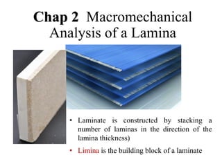
- 1. Chap 2 Macromechanical Analysis of a Lamina • Laminate is constructed by stacking a number of laminas in the direction of the lamina thickness) • Limina is the building block of a laminate
- 2. 2.1 Brief Review •Macromechanics means that the average mechanical properties are focused, ignoring the interaction of components in composites. •Generally, a single-layer board is analyzed in terms of a plane stress problem since its thickness is much smaller than its length and width. Only the in-plane stresses exist.
- 4. 12 31 23 3 2 1 66 56 46 36 26 16 56 55 45 35 25 15 46 45 44 34 24 14 36 35 34 33 23 13 26 25 24 23 22 12 16 15 14 13 12 11 12 31 23 3 2 1 C C C C C C C C C C C C C C C C C C C C C C C C C C C C C C C C C C C C • Constants Cij=Cji • C is symmetrical, including 21 independent constants. For anisotropic elastomers:
- 5. Material with one plane of symmetry • If the material has one symmetry plane, the number of elastic parameters is reduced to 13. 12 31 23 3 2 1 66 36 26 16 55 45 45 44 36 33 23 13 26 23 22 12 16 13 12 11 12 31 23 3 2 1 C 0 0 C C C 0 C C 0 0 0 0 C C 0 0 0 C 0 0 C C C C 0 0 C C C C 0 0 C C C 单对称材料
- 6. Orthotropic Material •More symmetry planes lead to the reduction of independent constants. -- If there are two symmetry planes -- 9 independent constants. 12 31 23 3 2 1 66 55 44 33 23 31 23 22 21 13 12 11 12 31 23 3 2 1 C 0 0 0 0 0 0 C 0 0 0 0 0 0 C 0 0 0 0 0 0 C C C 0 0 0 C C C 0 0 0 C C C No coupling!
- 7. Transversely Isotropic Material •Five independent constants 12 31 23 3 2 1 12 11 44 44 33 13 13 13 11 12 13 12 11 12 31 23 3 2 1 2 C C 0 0 0 0 0 0 C 0 0 0 0 0 0 C 0 0 0 0 0 0 C C C 0 0 0 C C C 0 0 0 C C C 2 C C C 12 11 66 Subscripts 1 and 2 can exchange
- 9. Constitutive equation(flexibility matrix) 12 31 23 3 2 1 66 56 46 36 26 16 56 55 45 35 25 15 46 45 44 34 24 14 36 35 34 33 23 13 26 25 24 23 22 12 16 15 14 13 12 11 12 31 23 3 2 1 S S S S S S S S S S S S S S S S S S S S S S S S S S S S S S S S S S S S • It is inverse to stiffness matrix • The both matrices has the same features
- 10. Flexibility matrix expressed by engineering constants 12 31 23 3 2 23 1 13 3 32 2 1 12 3 31 2 21 1 ij G 1 0 0 0 0 0 0 G 1 0 0 0 0 0 0 G 1 0 0 0 0 0 0 E 1 E E 0 0 0 E E 1 E 0 0 0 E E E 1 S (Orthotropic material)
- 11. 12 2 1 66 22 12 12 11 12 2 1 S 0 0 0 S S 0 S S 2.2 Relationship in Plane stress State (Orthotropic) 1 2 3 Only three stresses 1, 2,12 are non-zero. The flexibility matrix is simplified as
- 12. 12 12 12 2 2 ) 2 ( 2 2 1 12 ) 2 ( 1 1 1 12 ) 1 ( 2 1 1 ) 1 ( 1 G 1 E 1 E E E 1 1 2 1 2 12 1 2 12 Deducing… by 2.2 Relationship in Plane stress State (Orthotropic) by by No coupling!
- 13. Based on the superposition principle: 12 12 12 2 2 1 1 12 ) 2 ( 2 ) 1 ( 2 2 2 1 12 1 1 ) 2 ( 1 ) 1 ( 1 1 G 1 E 1 E E E 1 12 2 1 12 2 1 12 2 21 1 12 2 1 G 1 0 0 0 E 1 E 0 E E 1 12 2 1 66 22 12 12 11 12 2 1 S 0 0 0 S S 0 S S 12 66 2 22 2 21 1 12 12 1 11 G 1 S E 1 S E E S E 1 S
- 16. 34 . 0 , GPa 80 . 5 G , GPa 50 . 8 E , GPa 3 . 134 E 12 12 2 1 Try to calculate the stiffness constants and flexibility constants. GPa 80 . 5 G Q GPa 91 . 2 E m Q Q GPa 56 . 8 mE Q , GPa 3 . 135 mE Q 0074 . 1 ) E E 1 ( m , TPa 4 . 172 G / 1 S TPa 53 . 2 E / S S TPa 6 . 117 E / 1 S , TPa 45 . 7 E / 1 S 12 66 2 12 21 12 2 22 1 11 1 1 2 2 12 1 12 66 1 1 12 21 12 1 2 22 1 1 11 1 1 2 2 12 1 21 12 ) E E 1 ( ) 1 ( m Let Eg. The engineering constants for a lamina (T300/648) are
- 17. 2.3 Constitutive eq of single-layer board in arbitrary direction Coordinate Transformation is necessary when the principle directions are inconsistent with the geometric directions. Oblique to the shaft 1 2 y x +
- 18. Using the stresses σ1, σ2 and σ3 in 1-2 coordinate system to express σx, σy and σz in x-y coordinate system: 2.3 Constitutive eq of single-layer board in arbitrary direction T T 1 2 y x 1 cos( , ) l x x 2 cos( , ) l y x 3 cos( , ) l z x 1 cos( , ) m x y 2 cos( , ) m y y 3 cos( , ) m z y 1 cos( , ) n x z 2 cos( , ) n y z 3 cos( , ) n z z
- 19. 2 2 2 1 1 1 1 1 1 1 1 1 2 2 2 2 2 2 2 2 2 2 2 2 2 2 2 3 3 3 3 3 3 3 3 3 2 3 2 3 2 3 2 3 3 2 2 3 3 2 2 3 3 2 3 1 3 1 3 1 3 1 1 3 3 1 1 3 3 1 1 3 1 2 1 2 1 2 2 2 2 2 2 2 2 2 x y z yz zx xy l m n m n n l l m l m n m n n l l m l m n m n n l l m l l m m n n m n m n n l n l l m l m l l m m n n m n m n n l n l l m l m l l m m n n 2 1 2 2 1 1 2 2 1 1 2 2 1 x y z yz zx xy m n m n n l n l l m l m 2 2 2 1 1 1 1 1 1 1 1 1 2 2 2 2 2 2 2 2 2 2 2 2 2 2 2 3 3 3 3 3 3 3 3 3 2 3 2 3 2 3 2 3 3 2 2 3 3 2 2 3 3 2 3 1 3 1 3 1 3 1 1 3 3 1 1 3 3 1 1 3 1 2 1 2 1 2 2 2 2 2 2 2 2 2 x y z yz zx xy l m n m n nl l m l m n m n n l l m l m n m n n l l m l l m m n n m n m n n l n l l m l m l l m m n n m n m n n l nl l m l m l l m m n n 2 1 2 2 1 1 2 2 1 1 2 2 1 x y z yz zx xy m n m n nl n l l m l m
- 20. 12 2 1 2 2 2 2 2 2 xy y x sin cos cos sin cos sin cos sin 2 cos sin cos sin 2 sin cos Similarly, Coordinate transformation matrix 𝜀𝑥 𝜀𝑦 𝜏𝑥𝑦 = cos2𝜃 sin2𝜃 −sin𝜃cos𝜃 sin2 𝜃 cos2 𝜃 sin𝜃cos𝜃 2sin𝜃cos𝜃 −2sin𝜃cos𝜃 cos2𝜃 − sin2𝜃 𝜀1 𝜀2 𝜏12 T T
- 21. 12 2 1 66 11 12 12 11 12 2 1 xy y x Q 0 0 0 Q Q 0 Q Q 12 2 1 12 2 1 Q When the principle axises of material are consistent with the coordinate system: If inconsistent: 2.3 Constitutive eq of single-layer board in arbitrary direction 1 T S T S 1 T C T C T S T S T T C T C T
- 22. xy y x 66 26 16 26 22 12 16 12 11 xy y x xy y x Q Q Q Q Q Q Q Q Q Q ) sin (cos Q cos sin ) Q 2 Q 2 Q Q ( Q cos sin ) Q 2 Q Q ( cos sin ) Q 2 Q Q ( Q cos sin ) Q 2 Q Q ( cos sin ) Q 2 Q Q ( Q cos Q cos sin ) Q 2 Q ( 2 sin Q Q ) sin (cos Q cos sin ) Q 4 Q Q ( Q sin Q cos sin ) Q 2 Q ( 2 cos Q Q 4 4 66 2 2 66 12 22 11 66 3 66 22 12 3 66 12 11 26 3 66 22 12 3 66 12 11 16 4 22 2 2 66 12 4 11 22 4 4 12 2 2 66 22 11 12 4 22 2 2 66 12 4 11 11 • Nine non-zero constants. • Coupling phenomena occur in this generalized constitutive eq. for orthotropic materials. Be quite different from Q! Odd Even functions
- 23. 12 2 1 66 22 12 12 11 12 2 1 S 0 0 0 S S 0 S S xy y x 66 26 16 26 22 12 16 12 11 xy y x T xy y x S S S S S S S S S T S T ) sin (cos S cos sin ) S S 4 S 2 S 2 ( 2 S cos sin ) S S 2 S 2 ( cos sin ) S S 2 S 2 ( S cos sin ) S S 2 S 2 ( cos sin ) S S 2 S 2 ( S cos S cos sin ) S 2 S 2 ( sin S S ) sin (cos S cos sin ) S S S ( S sin S cos sin ) S S 2 ( cos S S 4 4 66 2 2 66 12 22 11 66 3 66 12 22 3 66 12 11 26 3 66 12 22 3 66 12 11 16 4 22 2 2 66 12 4 11 22 4 4 12 2 2 66 22 11 12 4 22 2 2 66 12 4 11 11 Similarly, the strain can be expressed by stress in x-y system:
- 24. 12 2 1 66 26 16 26 11 12 16 12 11 12 2 1 Q Q Q Q Q Q Q Q Q 12 2 1 66 26 16 26 22 12 16 12 11 12 2 1 S S S S S S S S S 12 12 , 2 2 3 , 12 26 12 12 , 1 1 1 , 12 16 12 66 2 22 2 21 1 12 12 1 11 G E S G E S G 1 S E 1 S E E S E 1 S i ij i , ij ij i ij , i The generalized constitutive eq. of a common anisotropic elastomer can be deduced in a similar way. Hint: The off-axis tension in composites leads to axial extension and shear strain! (New engineering constants — interaction coefficient )
- 25. i ij i , ij ij i ij , i New engineering constants — interaction coefficient The first kind: the extension in i-direction caused by the shear stress in i-j plane Off-axis tension in composites The second kind: the shear stress in i-j plane caused by the normal stress in i-direction
- 28. •Generalized elasticity modulus of anisotropic elastomers varies with the angle between the loading direction and the principle direction of composite material under off-axis loading. •The ultimate value of material performance (max. or min.) may not appear in the principle directions of material. •Performance of composites can be designed and optimized according to the above features. Summary
- 29. 2.4 Strength of Orthotropic Laminae Strength -- an important concept •Practically, a lamina is hardly used due to its low strength and stiffness in transverse direction. However, multi-layer composite board is often used as structural materials. •Purpose of this section is to express the strength in arbitrary direction by the properties in the principle directions of material. (differing from the traditional isotropic materials)
- 30. •Basic strength – in the principle of material Xt -- longitudinal tensile strength Xc -- longitudinal compressive stength Yt -- transverse tensile strength Yc -- transverse compressive strength S -- in-plane shear strength •They, together with E1,E2,12 and G12, are called engineering constants. (9 constants) •Strength is dependent of direction.
- 31. The strength of isotropic material reflects the material strength in simple loading state. •Plastic – yield stress or constraint yield stress •Brittle – ultimate stress •Others: shear yield stress, fatigue, etc. For orthotropic materials •Strength varies with direction •The mechanism of tensile failure differs from that of compressive failure •In-plane shear strength is independent.
- 32. Eg. A unidirectional fibre reinforced lamina is shown in Fig.1. 1 2 X Y S 2 2 2 cm / N 2000 S cm / N 1000 Y cm / N 50000 X Stress field 2 12 2 2 2 1 cm / N 1000 cm / N 2000 cm / N 45000 Fig. 1 The maximum principle stress σ1 is lower than the maximum material strength X, but the board will fail in 2-direction, resulting from the higher stress σ2 when compared to the strength in 2-direction. Conclusions Strength
- 33. •The shear strength in the principle direction is independent of tension and compression. The maximum value of shear stress -- constant regardless of the performance difference between compression and tension. -- invariable in spite of a positive shear stress or a positive shear stress. •The maximum value of the off-axis shear strength is dependent of the positive/negative sign of shear stress. Eg.
- 34. Different off-axis shear strengths 1 2 1 2 1 2 1 2 Shear in principle directions Shear at 45֠ to the principle axises complicate (identical max. ) (different shear strength) + - = =
- 35. Experimentally Determining Strength and Stiffness •Strength constants Xt Xc Yt Yc S •Stiffness constants E1 – elasticity modulus in 1-direction E2 – elasticity modulus in 1-direction 12 = 2/1, when 1= and other stress =0 21 = -1/2, when 2= and other stress = 0 G12 – shear modulus in 1-2 plane
- 36. •Basic principle in tests: The stress-strain relationship is linear with the increase of the load until failure. • Generally, the tensile curve exactly shows linear feature while the compressive curve and shear curve are nonlinear. •The key point in the tests is to load specimens evenly. Experimentally Determining Strength and Stiffness
- 37. Normal stress and shear strain Shear strain and normal stress Normal stress and bending curvature Bending stress and normal strain Coupling effect for orthotropic materials, the orthotropy often leads to coupling phenomena when the load is off-axis. Experimentally Determining Strength and Stiffness
- 38. Unidirectional tensile test in 1-direction 1 2 P P × 1 1 1 E1 1 max=X 1、2 can be determined by measurement A / P X E A / P max 1 2 12 1 1 1 1 Experimentally Determining Strength and Stiffness
- 39. Unidirectional tensile test in 2-direction 2 1 P P × 2 2 1 E2 2 max=Y Measure 1、2 A / P Y E A / P max 2 1 21 2 2 2 2 Experimentally Determining Strength and Stiffness
- 40. 2 21 1 12 E E Stiffness coefficients must meet the equation: The test devices are not accurate; Miscalculation; The stress-strain relationship of the tested material is nonlinear. If not Experimentally Determining Strength and Stiffness
- 41. Unidirectional test at 45 degrees to 1-axis 450 2 y 1 x P P x x 1 Ex 2 1 1 12 x 12 2 12 1 12 1 x x x E 1 E 1 E 2 E 4 1 G E 1 G 1 E 2 E 1 4 1 E 1 A / P E Measure x (G12 is determined) Based on Experimentally Determining Strength and Stiffness
- 42. 2.5 Bidirectional strength theory of anisotropic laminae • The above methods often used in unidirectional stress state. • Practically, an elastomer may be loaded in two or three directions. • A new failure criterion should be identified when loading in multi-directions. • Failure criterion is used for predicting failures. It is not the model of true failures and consequently the failure mechanism cannot be uncovered by it.
- 43. x y Failure Data × Failure × Yield 2.5 Bidirectional strength theory of anisotropic laminae Failure envelope -- combinations of the normal and shear stresses. Two-dimensional failure envelope with a given shear stress
- 44. 1. Maximum Stress Failure Theory In plane stress state, a failure is predicted in a unidirectional lamina if any stress component in the local axes equals or exceeds the corresponding ultimate strength. This criterion includes 3 independent expressions or 3 sub-criteria. The stress should be expressed in the principle axises of material. Description
- 45. S Y X 12 t 2 t 1 S Y X 12 c 2 c 1 cos sin S sin Y cos X cos sin sin cos x 2 x 2 t x x 12 2 x 2 2 x 1 Criterion Tensile Compressive Theoretical and experimental results are often conflicted
- 46. 2. Maximum Strain Failure Theory The criterion also includes 3 independent expressions or sub-criterions. Strain should be expressed in the material axes. Especially, a term incorporating Poisson’s ratio is involved in the expression, which indicates the effect of bidirectional stress is considered. The effect will be small if the Poisson’s ratio is small. Description In plane stress state, a failure is predicted if any strain component in the material axes exceeds the maximum strain.
- 47. Expressions S Y X 12 2 1 t t 12 12 12 1 21 2 2 2 2 12 1 1 1 G ) ( E 1 ) ( E 1 In 2-D state (plane stress state):
- 48. x 12 12 x 2 21 2 2 2 x 2 12 2 1 1 ) cos (sin G 1 ) cos (sin E 1 ) sin (cos E 1 2 c 1 c 12 2 t 1 t E Y Y E X X G S S E Y Y E X X c c t t cos sin S cos sin Y sin cos X x 2 21 2 x 2 12 2 t x cos sin sin cos x 12 2 x 2 2 x 1 Maximum Strain theory Big difference between theoretical and experimental results Unidirectional: Let
- 49. 3. Tsai-Hill Failure Theory 1 N 2 M 2 L 2 F 2 G 2 H 2 ) G F ( ) H F ( ) H G ( 2 12 2 13 2 23 3 2 3 1 2 1 2 3 2 2 2 1 Yield criterion where F, G, H, L, M, N are constants related to failure load. This theory is based on the Von-Mises’ distortional energy yield criterion.
- 50. Tsai-Hill Theory 2 2 2 2 Z 1 G F Y 1 H F X 1 H G S 1 N 2 If only 12 is applied If only 1 is applied If only 2 is applied If only 3 is applied 2 2 2 2 2 2 2 2 2 Z 1 Y 1 X 1 F 2 Z 1 Y 1 X 1 G 2 Z 1 Y 1 X 1 H 2 According to the criterion ( X, Y, Z are failure strengths in the three orthotropic directions, respectively )
- 51. 1 S Y X X 2 2 12 2 2 2 2 2 1 2 2 1 0 23 13 3 cos sin sin cos x 12 2 x 2 2 x 1 2 x 2 4 2 2 2 2 2 4 1 Y sin sin cos X 1 S 1 X cos Based on transformation eq. Hill-Tsai Theory Unidirectional loading For a unidimentional lamina under plane stress:
- 52. Features of Tsai-Hill Theory It is a failure criterion. Strength curve varying with direction angle is smooth without sharp point. Unidirectional strength decreases with respect to the direction angle (different from Max. Stress Theory and Max Strain Theory) The results are more consistent with experimental results. In Hill-Tsai theory, the interaction among the failure strengths X, Y and S is significantly considered, which is ignored by the other strength theory. The result for isotropic elastomers can be obtained by simplification.
- 53. Disadvantages It is not suitable for all materials. The function should be applied for compressive loading differs from the function for tensile loading. Hoffman suggested a adapted failure criterion for the materials with different behavior under compressive loading when compared to tensile loading. 1 S Y Y Y Y X X X X Y Y X X 2 2 12 2 c t t C 1 c t t C c t 2 2 c t 2 1 2 1 -- Hoffman failure criterion
- 54. 4. Tsai-Wu Failure Theory 6 , 2 , 1 j , i 1 F F j i ij i i 1 F 2 F F F F F F 2 1 12 2 6 66 2 2 22 2 1 11 6 6 2 2 1 1 Assume that the failure surface in stress space is ( Fi and Fij are coefficient tensors) 12 6 13 5 23 4 For orthotropic elastomers in plane stress state, This failure theory is based on the total strain energy failure theory of Beltrami.
- 55. Tsai-Wu Failure Theory 1 X F X F 2 t 11 t 1 c t 22 c t 2 Y Y 1 F Y 1 Y 1 F 1 X F X F 2 c 11 c 1 Apply 1=Xt, 2= 0=12: c t 11 c t 1 X X 1 F X 1 X 1 F Similarly in plane stress state Some components of the strength tensor can be determined by engineering parameters: The shear strength in the principle directions is independent of the positive/ negative sign of shear stress. Apply 1=Xc, 2= 0=12: Apply 1=0, 2= 0,12=S(-S)
- 56. Tsai-Wu Failure Theory 1 ) F 2 F F ( ) F F ( 2 12 22 11 2 1 The tensor coefficient Fij indicates the interaction of the stresses in two orthotropic directions (1 and 2). 2 1 2 c t c t c t c t 2 12 Y Y 1 X X 1 Y 1 Y 1 X 1 X 1 1 2 1 F Substituting the stresses into the tensor eq. in plane stress state yields If 2F12=-F11, the eq. is as same as Hoffman. If compressive strengths are identical, 2F12=-1/X2. (as same as Hill-Tsai eq.) Design a bidirectional tensile test:
- 57. Features of Tsai-Wu failure theory • The linear terms Fi describe the effect of unidirectional stress; • The quadratic terms Fij describe the effect of the space stresses, dependent of the interaction of the normal stressesi and j. • The quadratic terms Fij are symmetric. 6 , 2 , 1 j , i 1 F F j i ij i i