


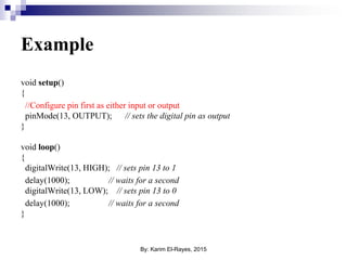
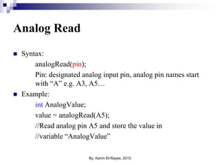
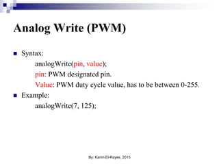
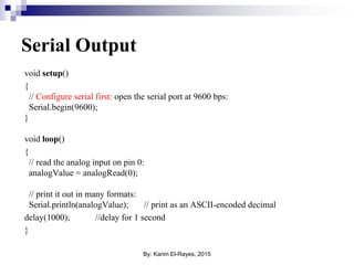
![Arrays
Array is a list of variables of the same type, instead of
declaring every variable separately they are declared in the
form list or “Array”.
Example:
int Numbers[10]; Array of 10 integers.
char MyArray[20]; Array of 20 character
Note: a string in C is just an array of characters.
By: Karim El-Rayes, 2015](https://image.slidesharecdn.com/introtoarduino-150408175822-conversion-gate01/85/Introduction-to-Arduino-28-320.jpg)

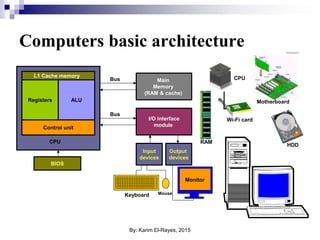
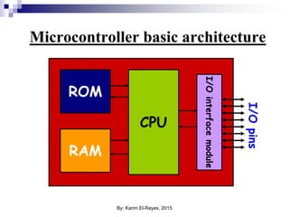
The document serves as an introduction to Arduino, covering the basic architecture of computers and microcontrollers, including components like CPUs, RAM, and input/output interfaces. It discusses programming microcontrollers using languages like C, the syntax for Arduino coding, and key concepts such as digital and analog signal processing. Additionally, it highlights various communication protocols and methods for controlling systems using Arduino, alongside examples of coding practices.