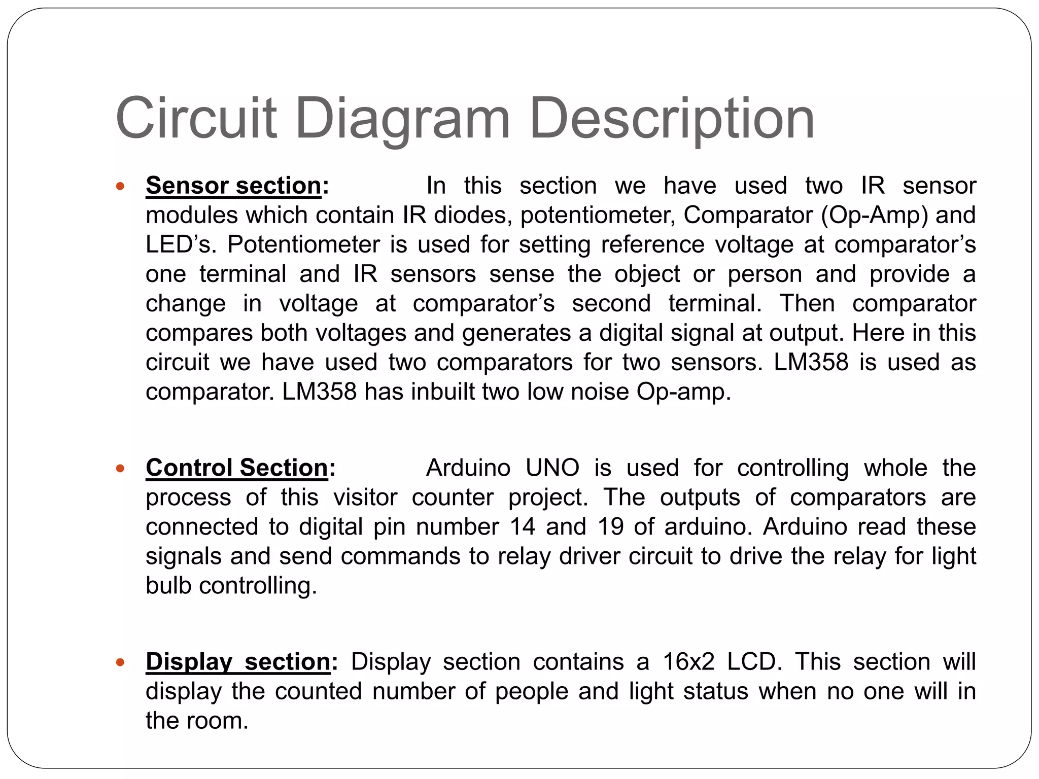
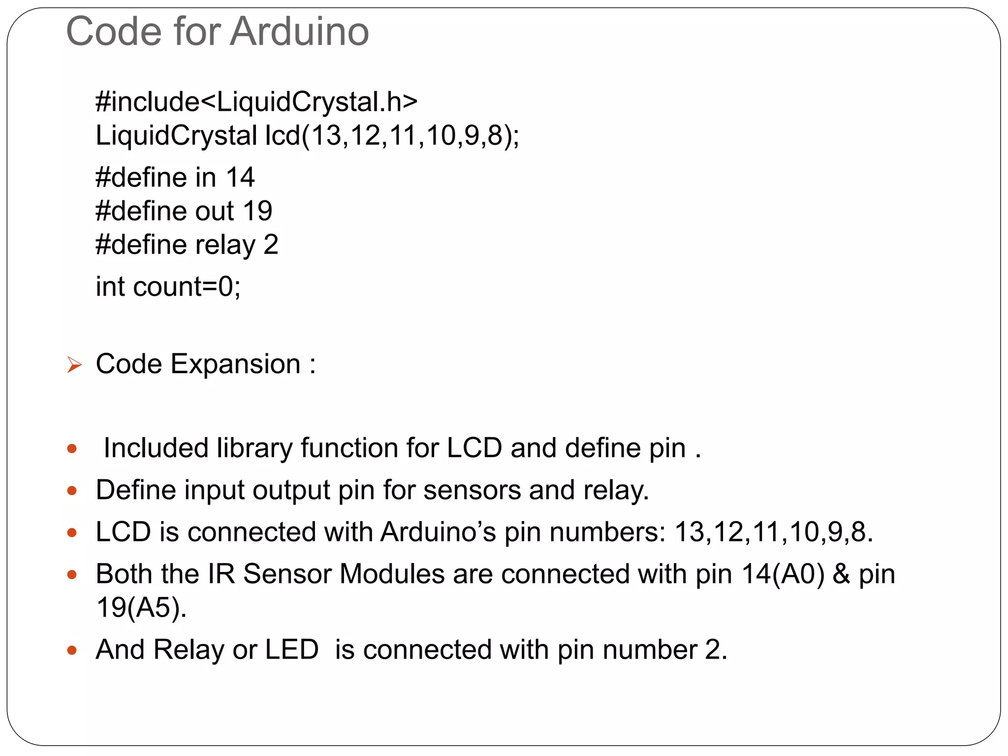
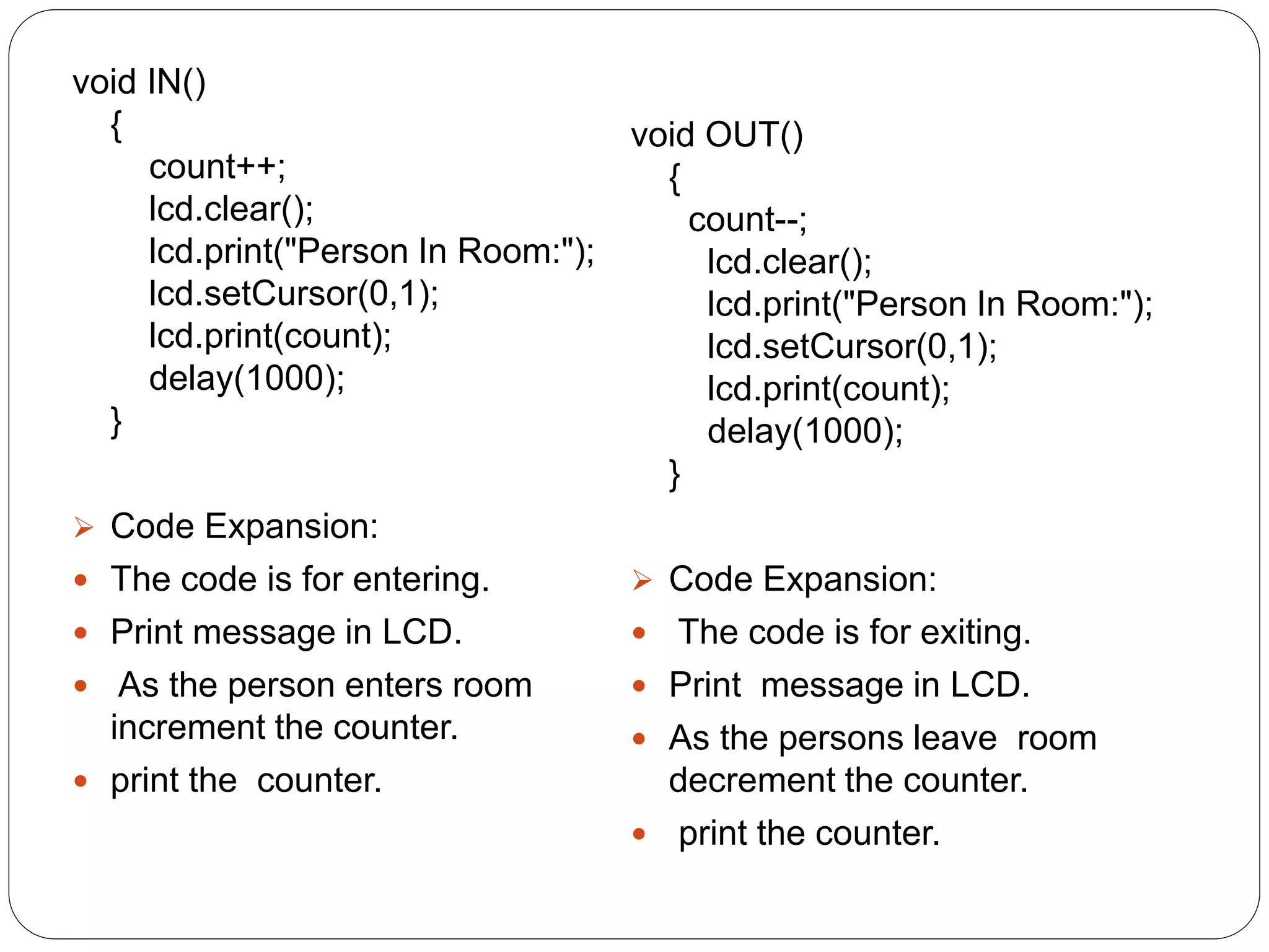
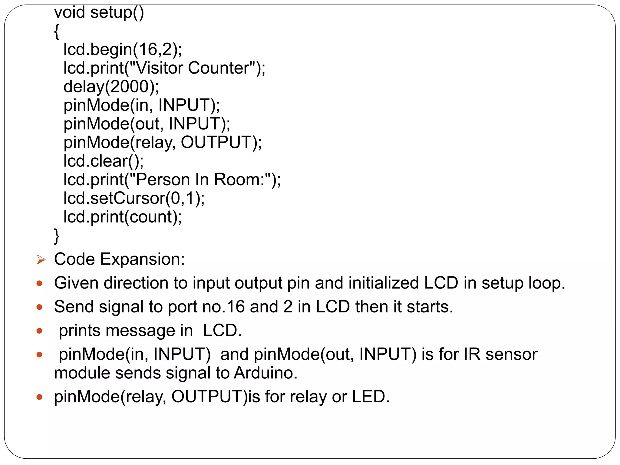
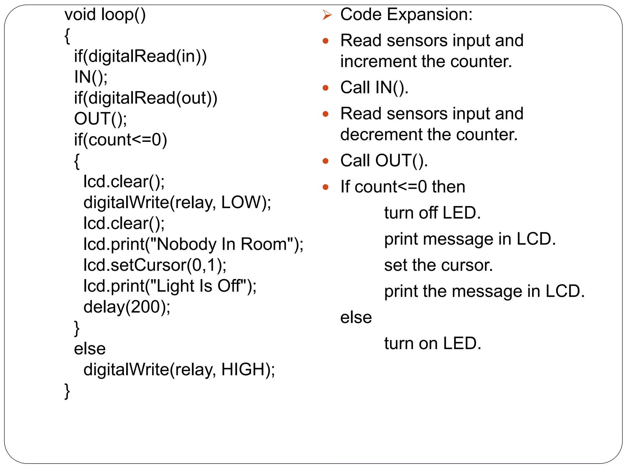
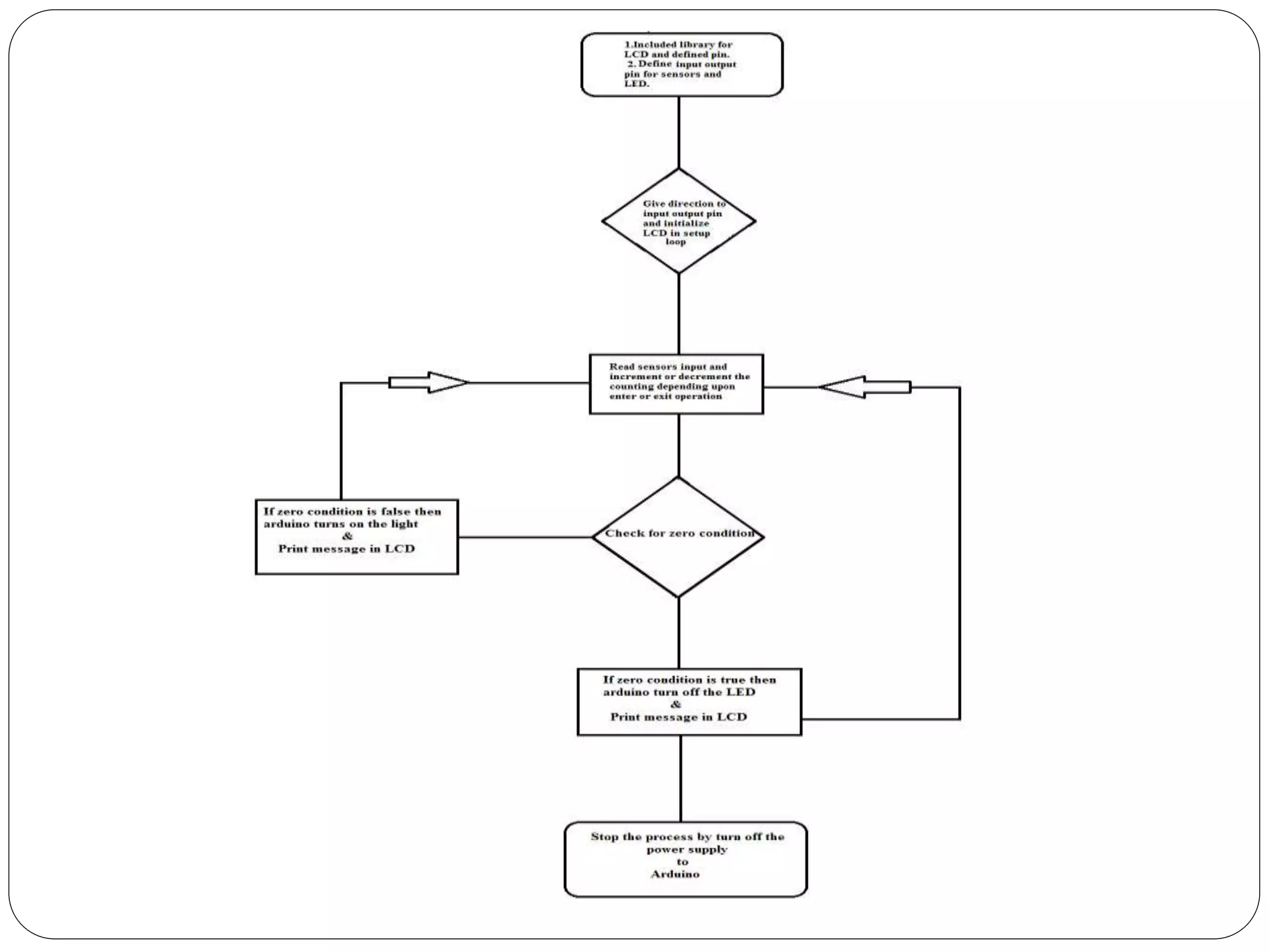
Prepared and Presented
by
Amrita Sil
Avik Adhikary
Mazhar Raza
Dipan Ghosh
Bidirectional Visitor Counter with
Automatic ON-OFF Switch
SILIGURI INSTITUTE OF TECHNOLOGY
SILIGURI -734004
Hardware Part
Circuit Diagram
Circuit Diagram Description
 Sensor section: In this section we have used two IR sensor
modules which contain IR diodes, potentiometer, Comparator (Op-Amp) and
LED’s. Potentiometer is used for setting reference voltage at comparator’s
one terminal and IR sensors sense the object or person and provide a
change in voltage at comparator’s second terminal. Then comparator
compares both voltages and generates a digital signal at output. Here in this
circuit we have used two comparators for two sensors. LM358 is used as
comparator. LM358 has inbuilt two low noise Op-amp.
 Control Section: Arduino UNO is used for controlling whole the
process of this visitor counter project. The outputs of comparators are
connected to digital pin number 14 and 19 of arduino. Arduino read these
signals and send commands to relay driver circuit to drive the relay for light
bulb controlling.
 Display section: Display section contains a 16x2 LCD. This section will
display the counted number of people and light status when no one will in
the room.
Code for Arduino
#include<LiquidCrystal.h>
LiquidCrystal lcd(13,12,11,10,9,8);
#define in 14
#define out 19
#define relay 2
int count=0;
 Code Expansion :
 Included library function for LCD and define pin .
 Define input output pin for sensors and relay.
 LCD is connected with Arduino’s pin numbers: 13,12,11,10,9,8.
 Both the IR Sensor Modules are connected with pin 14(A0) & pin
19(A5).
 And Relay or LED is connected with pin number 2.
void IN()
{
count++;
lcd.clear();
lcd.print("Person In Room:");
lcd.setCursor(0,1);
lcd.print(count);
delay(1000);
}
 Code Expansion:
 The code is for entering.
 Print message in LCD.
 As the person enters room
increment the counter.
 print the counter.
void OUT()
{
count--;
lcd.clear();
lcd.print("Person In Room:");
lcd.setCursor(0,1);
lcd.print(count);
delay(1000);
}
 Code Expansion:
 The code is for exiting.
 Print message in LCD.
 As the persons leave room
decrement the counter.
 print the counter.
void setup()
{
lcd.begin(16,2);
lcd.print("Visitor Counter");
delay(2000);
pinMode(in, INPUT);
pinMode(out, INPUT);
pinMode(relay, OUTPUT);
lcd.clear();
lcd.print("Person In Room:");
lcd.setCursor(0,1);
lcd.print(count);
}
 Code Expansion:
 Given direction to input output pin and initialized LCD in setup loop.
 Send signal to port no.16 and 2 in LCD then it starts.
 prints message in LCD.
 pinMode(in, INPUT) and pinMode(out, INPUT) is for IR sensor
module sends signal to Arduino.
 pinMode(relay, OUTPUT)is for relay or LED.
void loop()
{
if(digitalRead(in))
IN();
if(digitalRead(out))
OUT();
if(count<=0)
{
lcd.clear();
digitalWrite(relay, LOW);
lcd.clear();
lcd.print("Nobody In Room");
lcd.setCursor(0,1);
lcd.print("Light Is Off");
delay(200);
}
else
digitalWrite(relay, HIGH);
}
 Code Expansion:
 Read sensors input and
increment the counter.
 Call IN().
 Read sensors input and
decrement the counter.
 Call OUT().
 If count<=0 then
turn off LED.
print message in LCD.
set the cursor.
print the message in LCD.
else
turn on LED.
Thank You

Bidirectional Visitor Counter with Automatic ON-OFF Switch2

  • 1.
    Prepared and Presented by AmritaSil Avik Adhikary Mazhar Raza Dipan Ghosh Bidirectional Visitor Counter with Automatic ON-OFF Switch SILIGURI INSTITUTE OF TECHNOLOGY SILIGURI -734004
  • 2.
  • 3.
  • 4.
    Circuit Diagram Description Sensor section: In this section we have used two IR sensor modules which contain IR diodes, potentiometer, Comparator (Op-Amp) and LED’s. Potentiometer is used for setting reference voltage at comparator’s one terminal and IR sensors sense the object or person and provide a change in voltage at comparator’s second terminal. Then comparator compares both voltages and generates a digital signal at output. Here in this circuit we have used two comparators for two sensors. LM358 is used as comparator. LM358 has inbuilt two low noise Op-amp.  Control Section: Arduino UNO is used for controlling whole the process of this visitor counter project. The outputs of comparators are connected to digital pin number 14 and 19 of arduino. Arduino read these signals and send commands to relay driver circuit to drive the relay for light bulb controlling.  Display section: Display section contains a 16x2 LCD. This section will display the counted number of people and light status when no one will in the room.
  • 5.
    Code for Arduino #include<LiquidCrystal.h> LiquidCrystallcd(13,12,11,10,9,8); #define in 14 #define out 19 #define relay 2 int count=0;  Code Expansion :  Included library function for LCD and define pin .  Define input output pin for sensors and relay.  LCD is connected with Arduino’s pin numbers: 13,12,11,10,9,8.  Both the IR Sensor Modules are connected with pin 14(A0) & pin 19(A5).  And Relay or LED is connected with pin number 2.
  • 6.
    void IN() { count++; lcd.clear(); lcd.print("Person InRoom:"); lcd.setCursor(0,1); lcd.print(count); delay(1000); }  Code Expansion:  The code is for entering.  Print message in LCD.  As the person enters room increment the counter.  print the counter. void OUT() { count--; lcd.clear(); lcd.print("Person In Room:"); lcd.setCursor(0,1); lcd.print(count); delay(1000); }  Code Expansion:  The code is for exiting.  Print message in LCD.  As the persons leave room decrement the counter.  print the counter.
  • 7.
    void setup() { lcd.begin(16,2); lcd.print("Visitor Counter"); delay(2000); pinMode(in,INPUT); pinMode(out, INPUT); pinMode(relay, OUTPUT); lcd.clear(); lcd.print("Person In Room:"); lcd.setCursor(0,1); lcd.print(count); }  Code Expansion:  Given direction to input output pin and initialized LCD in setup loop.  Send signal to port no.16 and 2 in LCD then it starts.  prints message in LCD.  pinMode(in, INPUT) and pinMode(out, INPUT) is for IR sensor module sends signal to Arduino.  pinMode(relay, OUTPUT)is for relay or LED.
  • 8.
    void loop() { if(digitalRead(in)) IN(); if(digitalRead(out)) OUT(); if(count<=0) { lcd.clear(); digitalWrite(relay, LOW); lcd.clear(); lcd.print("NobodyIn Room"); lcd.setCursor(0,1); lcd.print("Light Is Off"); delay(200); } else digitalWrite(relay, HIGH); }  Code Expansion:  Read sensors input and increment the counter.  Call IN().  Read sensors input and decrement the counter.  Call OUT().  If count<=0 then turn off LED. print message in LCD. set the cursor. print the message in LCD. else turn on LED.
  • 10.