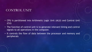
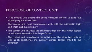
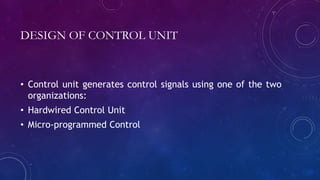
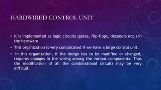
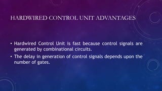
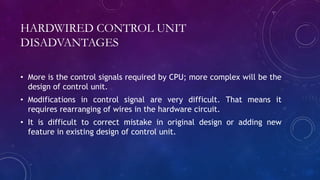
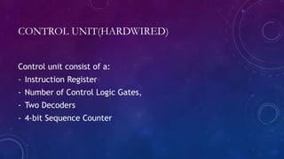
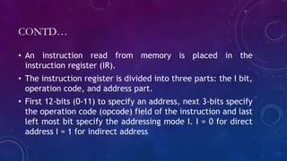
TIMING AND CONTROL
UNIT
CONTROL UNIT
• CPU is partitioned into Arithmetic Logic Unit (ALU) and Control Unit
(CU)
• The function of control unit is to generate relevant timing and control
signals to all operations in the computer.
• It controls the flow of data between the processor and memory and
peripherals
FUNCTIONS OF CONTROL UNIT
• The control unit directs the entire computer system to carry out
stored program instructions.
• The control unit must communicate with both the arithmetic logic
unit (ALU) and main memory.
• The control unit instructs the arithmetic logic unit that which logical
or arithmetic operation is to be performed.
• The control unit co-ordinates the activities of the other two units as
well as all peripherals and auxiliary storage devices linked to the
computer.
DESIGN OF CONTROL UNIT
• Control unit generates control signals using one of the two
organizations:
• Hardwired Control Unit
• Micro-programmed Control
HARDWIRED CONTROL UNIT
• It is implemented as logic circuits (gates, flip-flops, decoders etc.) in
the hardware.
• This organization is very complicated if we have a large control unit.
• In this organization, if the design has to be modified or changed,
requires changes in the wiring among the various components. Thus
the modification of all the combinational circuits may be very
difficult.
HARDWIRED CONTROL UNIT ADVANTAGES
• Hardwired Control Unit is fast because control signals are
generated by combinational circuits.
• The delay in generation of control signals depends upon the
number of gates.
HARDWIRED CONTROL UNIT
DISADVANTAGES
• More is the control signals required by CPU; more complex will be the
design of control unit.
• Modifications in control signal are very difficult. That means it
requires rearranging of wires in the hardware circuit.
• It is difficult to correct mistake in original design or adding new
feature in existing design of control unit.
CONTROL UNIT(HARDWIRED)
Control unit consist of a:
- Instruction Register
- Number of Control Logic Gates,
- Two Decoders
- 4-bit Sequence Counter
CONTD…
• An instruction read from memory is placed in the
instruction register (IR).
• The instruction register is divided into three parts: the I bit,
operation code, and address part.
• First 12-bits (0-11) to specify an address, next 3-bits specify
the operation code (opcode) field of the instruction and last
left most bit specify the addressing mode I. I = 0 for direct
address I = 1 for indirect address
CONTD..
• First 12-bits (0-11) are applied to the control logic gates.
• The operation code bits (12 – 14) are decoded with a 3 x 8
decoder.
• The eight outputs ( D0 through D7) from a decoder goes to
the control logic gates to perform specific operation.
• Last bit 15 is transferred to a I flip-flop designated by
symbol I.
CONTD…
• The 4-bit sequence counter SC can count in binary from 0
through 15.
• The counter output is decoded into 16 timing pulses T0
through T15.
• The sequence counter can be incremented by INR input or
clear by CLR input synchronously.
CONTD…
• For example: Consider the case where SC is incremented to
provide timing signals T0, T1, T 2 , T3, and T4 in sequence.
At time T4 , SC is cleared to 0 if decoder output D3 is
active. This is expressed symbolically by the statement:
D3 T4 : SC ← 0
• The timing diagram shows the time relationship of the
control signals.
Timing and control unit

Timing and control unit

  • 1.
  • 2.
    CONTROL UNIT • CPUis partitioned into Arithmetic Logic Unit (ALU) and Control Unit (CU) • The function of control unit is to generate relevant timing and control signals to all operations in the computer. • It controls the flow of data between the processor and memory and peripherals
  • 3.
    FUNCTIONS OF CONTROLUNIT • The control unit directs the entire computer system to carry out stored program instructions. • The control unit must communicate with both the arithmetic logic unit (ALU) and main memory. • The control unit instructs the arithmetic logic unit that which logical or arithmetic operation is to be performed. • The control unit co-ordinates the activities of the other two units as well as all peripherals and auxiliary storage devices linked to the computer.
  • 4.
    DESIGN OF CONTROLUNIT • Control unit generates control signals using one of the two organizations: • Hardwired Control Unit • Micro-programmed Control
  • 5.
    HARDWIRED CONTROL UNIT •It is implemented as logic circuits (gates, flip-flops, decoders etc.) in the hardware. • This organization is very complicated if we have a large control unit. • In this organization, if the design has to be modified or changed, requires changes in the wiring among the various components. Thus the modification of all the combinational circuits may be very difficult.
  • 6.
    HARDWIRED CONTROL UNITADVANTAGES • Hardwired Control Unit is fast because control signals are generated by combinational circuits. • The delay in generation of control signals depends upon the number of gates.
  • 7.
    HARDWIRED CONTROL UNIT DISADVANTAGES •More is the control signals required by CPU; more complex will be the design of control unit. • Modifications in control signal are very difficult. That means it requires rearranging of wires in the hardware circuit. • It is difficult to correct mistake in original design or adding new feature in existing design of control unit.
  • 8.
    CONTROL UNIT(HARDWIRED) Control unitconsist of a: - Instruction Register - Number of Control Logic Gates, - Two Decoders - 4-bit Sequence Counter
  • 10.
    CONTD… • An instructionread from memory is placed in the instruction register (IR). • The instruction register is divided into three parts: the I bit, operation code, and address part. • First 12-bits (0-11) to specify an address, next 3-bits specify the operation code (opcode) field of the instruction and last left most bit specify the addressing mode I. I = 0 for direct address I = 1 for indirect address
  • 11.
    CONTD.. • First 12-bits(0-11) are applied to the control logic gates. • The operation code bits (12 – 14) are decoded with a 3 x 8 decoder. • The eight outputs ( D0 through D7) from a decoder goes to the control logic gates to perform specific operation. • Last bit 15 is transferred to a I flip-flop designated by symbol I.
  • 12.
    CONTD… • The 4-bitsequence counter SC can count in binary from 0 through 15. • The counter output is decoded into 16 timing pulses T0 through T15. • The sequence counter can be incremented by INR input or clear by CLR input synchronously.
  • 14.
    CONTD… • For example:Consider the case where SC is incremented to provide timing signals T0, T1, T 2 , T3, and T4 in sequence. At time T4 , SC is cleared to 0 if decoder output D3 is active. This is expressed symbolically by the statement: D3 T4 : SC ← 0 • The timing diagram shows the time relationship of the control signals.