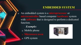
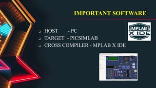
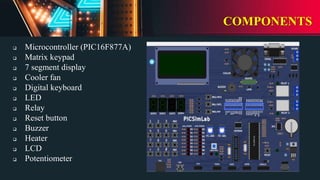
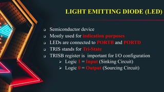
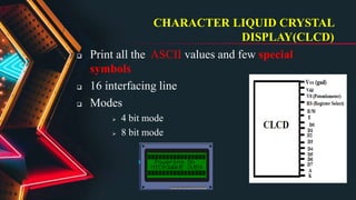
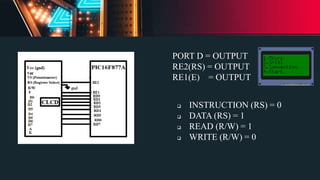
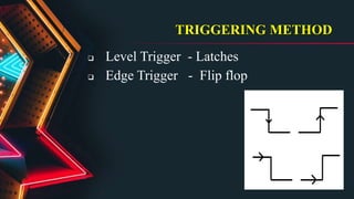
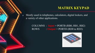
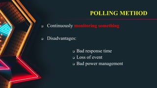
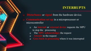
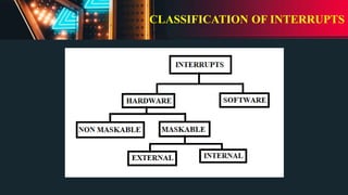
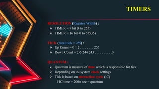
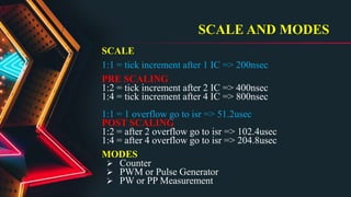
MICROWAVE OVEN
by
BOOMIKA D
BANNARI AMMAN INSTITUTE
OF TECHNOLOGY
EMBEDDED SYSTEM
 An embedded system is a microprocessor or
microcontroller based computer hardware system
with software that is designed to perform a dedicated
function.
Example:
 Mobile phone
 Microwave oven
 GPS system
IMPORTANT SOFTWARE
❏ HOST - PC
❏ TARGET - PICSIMLAB
❏ CROSS COMPILER - MPLAB X IDE
COMPONENTS
 Microcontroller (PIC16F877A)
 Matrix keypad
 7 segment display
 Cooler fan
 Digital keyboard
 LED
 Relay
 Reset button
 Buzzer
 Heater
 LCD
 Potentiometer
LIGHT EMITTING DIODE (LED)
 Semiconductor device
 Mostly used for indication purposes
 LEDs are connected to PORTB and PORTD
 TRIS stands for Tri-State
 TRISB register is important for I/O configuration
 Logic 1 = Input (Sinking Circuit)
 Logic 0 = Output (Sourcing Circuit)
CHARACTER LIQUID CRYSTAL
DISPLAY(CLCD)
 Print all the ASCII values and few special
symbols
 16 interfacing line
 Modes
 4 bit mode
 8 bit mode
PORT D = OUTPUT
RE2(RS) = OUTPUT
RE1(E) = OUTPUT
 INSTRUCTION (RS) = 0
 DATA (RS) = 1
 READ (R/W) = 1
 WRITE (R/W) = 0
TRIGGERING METHOD
 Level Trigger - Latches
 Edge Trigger - Flip flop
MATRIX KEYPAD
 Mostly used in telephones, calculators, digital lockers, and
a variety of other applications.
COLUMNS : Input = PORTB (RB0, RB1, RB2)
ROWS : Output = PORTD (RD0 to RD3)
POLLING METHOD
 Continuously monitoring something
 Disadvantages:
 Bad response time
 Loss of event
 Bad power management
INTERRUPTS
 Disturbance or signal from the hardware device.
 Communication set up in a microprocessor or
microcontroller
❏ An internal or external device requests the MPU
to stop the processing
❏ The MPU acknowledges the request
❏ Attends to the request
❏ Goes back to processing where it was interrupted
.
CLASSIFICATION OF INTERRUPTS
TIMERS
RESOLUTION (Register Width) :
 TIMER = 8 bit (0 to 255)
 TIMER = 16 bit (0 to 65535)
TICK (total tick = 255) :
 Up Count = 0 1 2 . . . . . . . . 255
 Down Count = 255 244 243 . . . . . . . . . .0
QUANTUM :
 Quantum is measure of time which is responsible for tick.
 Depending on the system clock settings
 Tick is based on instruction cycle (IC)
1 IC time = 200 n sec = quantum
SCALE AND MODES
SCALE
1:1 = tick increment after 1 IC => 200nsec
PRE SCALING
1:2 = tick increment after 2 IC => 400nsec
1:4 = tick increment after 4 IC => 800nsec
1:1 = 1 overflow go to isr => 51.2usec
POST SCALING
1:2 = after 2 overflow go to isr => 102.4usec
1:4 = after 4 overflow go to isr => 204.8usec
MODES
 Counter
 PWM or Pulse Generator
 PW or PP Measurement
THANK YOU

Embedded Systems using Microwave oven

  • 1.
    MICROWAVE OVEN by BOOMIKA D BANNARIAMMAN INSTITUTE OF TECHNOLOGY
  • 2.
    EMBEDDED SYSTEM  Anembedded system is a microprocessor or microcontroller based computer hardware system with software that is designed to perform a dedicated function. Example:  Mobile phone  Microwave oven  GPS system
  • 3.
    IMPORTANT SOFTWARE ❏ HOST- PC ❏ TARGET - PICSIMLAB ❏ CROSS COMPILER - MPLAB X IDE
  • 4.
    COMPONENTS  Microcontroller (PIC16F877A) Matrix keypad  7 segment display  Cooler fan  Digital keyboard  LED  Relay  Reset button  Buzzer  Heater  LCD  Potentiometer
  • 5.
    LIGHT EMITTING DIODE(LED)  Semiconductor device  Mostly used for indication purposes  LEDs are connected to PORTB and PORTD  TRIS stands for Tri-State  TRISB register is important for I/O configuration  Logic 1 = Input (Sinking Circuit)  Logic 0 = Output (Sourcing Circuit)
  • 6.
    CHARACTER LIQUID CRYSTAL DISPLAY(CLCD) Print all the ASCII values and few special symbols  16 interfacing line  Modes  4 bit mode  8 bit mode
  • 7.
    PORT D =OUTPUT RE2(RS) = OUTPUT RE1(E) = OUTPUT  INSTRUCTION (RS) = 0  DATA (RS) = 1  READ (R/W) = 1  WRITE (R/W) = 0
  • 8.
    TRIGGERING METHOD  LevelTrigger - Latches  Edge Trigger - Flip flop
  • 9.
    MATRIX KEYPAD  Mostlyused in telephones, calculators, digital lockers, and a variety of other applications. COLUMNS : Input = PORTB (RB0, RB1, RB2) ROWS : Output = PORTD (RD0 to RD3)
  • 10.
    POLLING METHOD  Continuouslymonitoring something  Disadvantages:  Bad response time  Loss of event  Bad power management
  • 11.
    INTERRUPTS  Disturbance orsignal from the hardware device.  Communication set up in a microprocessor or microcontroller ❏ An internal or external device requests the MPU to stop the processing ❏ The MPU acknowledges the request ❏ Attends to the request ❏ Goes back to processing where it was interrupted .
  • 12.
  • 13.
    TIMERS RESOLUTION (Register Width):  TIMER = 8 bit (0 to 255)  TIMER = 16 bit (0 to 65535) TICK (total tick = 255) :  Up Count = 0 1 2 . . . . . . . . 255  Down Count = 255 244 243 . . . . . . . . . .0 QUANTUM :  Quantum is measure of time which is responsible for tick.  Depending on the system clock settings  Tick is based on instruction cycle (IC) 1 IC time = 200 n sec = quantum
  • 14.
    SCALE AND MODES SCALE 1:1= tick increment after 1 IC => 200nsec PRE SCALING 1:2 = tick increment after 2 IC => 400nsec 1:4 = tick increment after 4 IC => 800nsec 1:1 = 1 overflow go to isr => 51.2usec POST SCALING 1:2 = after 2 overflow go to isr => 102.4usec 1:4 = after 4 overflow go to isr => 204.8usec MODES  Counter  PWM or Pulse Generator  PW or PP Measurement
  • 15.