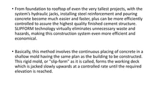
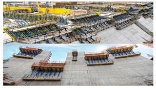
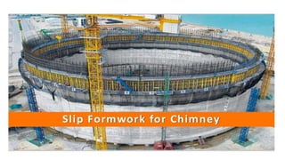
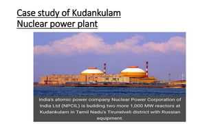
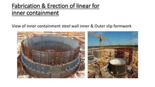
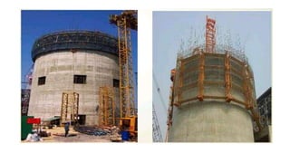
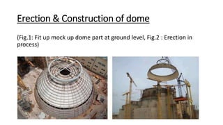
SLIP FORMWORK FOR
CHIMNEY
Submitted by,
ABHISHEK PARMAR (20MCL001)
AXAY SHARMA (20MCL002)
DHRUVIL DEVANI (20MCL003)
ANJALI JAIN (20MCL004)
AASH PANKHANIYA (20MCL005)
CONTENT
• Introduction to slip formwork
• Pictures of traditional slip Form work
• Slip Formwork For Chimney
• Procedure
• Steps of slip form work .
• Structural Concerns
• Components
• Advantage And Disadvantages
• Case Study
INTRODUCTION
• Slip-form construction is a method for Building large towers or
bridges from Concrete. The name refers to the moving form the
concrete is poured into, which moves along the project as the
previously poured concrete hardens behind it. The technique has also
been applied to road construction.
• “The technique was in use by the Early 20th Century for building silos
and grain elevators.”
• Vertical slip-form relies on the quick-setting properties of concrete
requiring a balance between early strength gain and workability.
Concrete needs to be workable enough to be placed to the formwork
and strong enough to develop early strength so that the form can slip
upwards without any disturbance to the freshly placed concrete.
• A notable use of the method was the Skylon Tower in Niagara Falls,
Ontario, which was completed in 1965. The technique was soon
utilized to build the Inco Super stack in Sudbury, Ontario and the CN
Tower in Toronto. It is the most common method for construction of
tall buildings in Australia.
• From foundation to rooftop of even the very tallest projects, with the
system’s hydraulic jacks, installing steel reinforcement and pouring
concrete become much easier and faster, plus can be more efficiently
controlled to assure the highest quality finished cement structure.
SLIPFORM technology virtually eliminates unnecessary waste and
hazards, making this construction system even more efficient and
economical.
• Basically, this method involves the continuous placing of concrete in a
shallow mold having the same plan as the building to be constructed.
This rigid mold, or "slip-form" as it is called, forms the working deck
which is jacked slowly upwards at a controlled rate until the required
elevation is reached.
SLIP FORM TECHNOLOGY
• Method of vertically extruding a reinforced concrete section and is
suitable for construction of core walls in high-rise structures – lift
shafts, stair shafts, towers.
• The formwork rises continuously, at a rate of about 300 mm per hour,
supporting itself on the core and not relying on support or access
from other parts of the building or permanent works.
• Allows for the continuous pouring of concrete into walls of a structure
and only stops when the full required height of the structure has
been reached.
• The height of the formwork is designed in such a way that while the
top of the formwork is being filled by concrete the lowest layer of
concrete poured earlier has already gained an initial set. When the
formwork is moved upwards the concrete that is then exposed
remains firm.
Steps & Points
1. Assembly can Only Start Once The Foundations Are In Place and the
wall starter is in correct alignment.
2. Slip form shuttering is aligned with the help of yokes.
3. Horizontal crossbeams connect the yokes.
4. Hydraulic jacks are attached to these Crossbeams for simultaneous
upward movement.
5. Height of the slip form ranges from 1.1-1.5 meters.
6. Yokes and crossbeams also used to support the working platform.
7. Structure should be rigid and shape maintained at all times.
8. Make sure there is no lag or else it prevents the structure from free
upward movement
9. It is also possible to reduce wall thicknesses
10. as the construction gains height and arrangements have to be made
in the slip form structure that will enable such reduction at regular
intervals.
Components
• Work deck
• Slip-form jack
• Yoke
• Form panels
• Hanging scaffolding
• walers
Structural Concerns
1. It is necessary to use a low slump concrete in slip forming processes
where the formwork is moved horizontally in order for the slab or
pavement to retain its shape as the paving machine advances.
2. Presently, slip form pavements use “high early strength.” concrete,
which achieves the required strength in approximately 12 hours, as
compared to conventional concrete which requires 5-14 days.
3. The water content of this type of concrete is lower than it is for
standard material, resulting in improved strength as well as improved
resistance to the permeation of salt, thereby increasing the finished
concrete's resistance to deterioration from chloride ions.
PRECAUTIONS
• Concrete is continuously protected against loss of moisture and rapid
temperature changes for 7 days
• Unhardened concrete is protected from rain and flowing water
• Prevent plastic shrinkage
• Plastic cracks are filled by injection of epoxy resin.
RELATION BETWEEN CONCRETE
SETTING TIME AND SLIPFORM RATE
• It is calculated by using the following
equation:
• Vs = (H1- H2 ) / (ts– tt)
• Where
• Vs – slip-form rate (mm / h)
• H1 = the distance from the top of the
slipform panel to the average curing front
(mm)
• H2 = The distance from the top of the
slipform panel to average freeboard (mm)
• Ts = setting time (h)
• Tt = Time from mixing concrete to placing
Advantages and Disadvantages of Slip-
formwork
ADVANTAGES
• Non-stop Method of Construction
• Increase rate of construction
• Increase the productivity
• Provide more working space
• Creates safe work environment for the
workers
• Cost effective
• The reduction in the movement of formwork and workers also leads
to far more safe working conditions that also make it a major
advantage.
• Great reduction in the cost of formwork as well as time saving for re-
erection.
• Continuous use of manpower and lifting equipment like cranes.
SUSTAINABILITY FEATURES :
❖The formwork system is easy to clean and reuse with little formwork
waste generated compared to traditional formwork.
❖Climbing formwork systems offer simplicity, safety and cost
effectiveness for certain high-rise building structures.
❖ Many repeated uses of formwork are possible before maintenance
or replacement is needed, the number of uses depending on the
quality of the surface finish of concrete specified.
❖ The repetitive nature of the work, combined with the engineered
nature of the formwork, allows fine tuning of the construction
operations, which in turn leads to minimal concrete wastage.
APPLICATIONS OF SLIP-FORM CONSTRUCTION
• Slip-form construction is used for tall structures, such as towers,
buildings, and dams, as well as horizontal structures, such as roadway
barriers. It enables continuous, non-interrupted, cast-in-place joint-less
concrete structures which have superior performance characteristics
over construction methods using discrete form elements. Slip forming
relies on the quick setting properties of concrete, and requires a
balance between quick-setting capacity and workability.
DISADAVANTAGES :
• The materials deliveries, such as concrete and reinforcing steel,
should be made on schedule in order to develop a maximum rate of
slip.
• Specialized help is required for the duration of the slip form work,
much more so than in conventional construction.
• It is imperative that some person thoroughly familiar with the overall
operation be on the form at all times If care is taken in the planning
stage and carried through the complete operation, many of the normal
pitfalls can be avoided and an efficient operation can be achieved.
Case study of Kudankulam
Nuclear power plant
• Client :Nuclear Power Corporation of India Ltd.
• Contract value : Rs. 6210 Million
• Project Location :Tamil Nadu
• Construction of 2X 1000 Mwe nuclear power project with collobration
with Russian government.
• HCC has been in the forefront of construction Nuclear power projects
and has build built 50% of india’s nuclear power generation capacity.
Civil works of the entire project was mainly divided into six packages:
• Package 1 : Earth work
• Package 2 : Subsoil Investigation
• Package 3 : Construction of reactor building & reactor auxillary
buildings & associates
• Package 4: Construction of Turbine buildings & Associated Works
• Package 5: Construction of Auxiliary buildings & Associated Works
• Package 6: Construction of Hydro technical structures& Associated
Works
Components Slipform (Kudankulam Nuclear Power Plant)
Procedure
• Assembly can only start once the foundations are in place and the wall starter is in correct
alignment.
• Slip form shuttering is aligned with the help of yokes.Horizontal crossbeams connect these yokes.
• Hydraulic jacks are attached to these crossbeams for simultaneous upward movement.
• Height of the slip form ranges from 1.1 to 1.5 meters.
• Yokes and crossbeams also used to support the working platform.
• Structure should be rigid and shape maintained at all times. Make sure there is no lag or else it
prevents the structure from free upward movement.
• It is also possible to reduce wall thicknesses as the construction gains height and arrangements
have to be made in the slip form structure that will enable such reduction at regular intervals.
Construction of reactor building & reactor
auxillary buildings & associates
• Structural work of two reactor building
along with auxiliary & Control room
buildings.
• Height : 88 meters
• Foundation : Raft foundation at 8.85 m
below GL.
• Thickness 4.6 m at End & 1.6 m at Middle
• Base Slab upto 1.1 m above GL.
• 6000 m3 concrete required.
(Source:www.hccindia.com)
Fabrication & Erection of linear for
inner containment
View of inner containment steel wall inner & Outer slip formwork
• Detailed planning was required to fabricate the liners of the 44m
diameter walls.
• The cylindrical part of linear to cover a height of 38.5m and have been
made in 8 tiers.
• The maximum height of one tier is 6.5m.
• Each segment is made of 6mm thick steel sheet stiffened by structural
section on backside.
• All welded joints were subjected to 100% leak tightness test by
vacuums box & 20% Ultrasonic examination.
• In order to take care of correct fabrication ,Jigs were fabricated
Inspected and cleared for each type of panel for mass production.
Erection & Construction of dome
(Fig.1: Fit up mock up dome part at ground level, Fig.2 : Erection in
process)
Erection
• Dome liner is of hemispherical shape of 22mradius made out of 6mm thick
radius.
• Part 1 : 5.60m Height and of 15 segments in situ.
• Part 2 :7.6m Height
• Part 3: 8.8 m Height
• special feature undertaken in India for the first time is a completely steel
lined dome of the inner containment of the reactor building. The dome
was constructed in three parts.
• Two of the three parts , weighing 90 metric tons (MT) and 159 MT each
were fabricated and assembled on the ground.
• A 650MT crane was then used to lift these dome assemblies and place
them at a level around 57 meters from the ground.
Concreting of Dome
• Slab Thickness : 600 mm
References
• https://www.google.com/amp/s/www.indiatvnews.com/amp/news/i
ndia/kudankulam-nuclear-power-plant-russia-ships-equipment-
627451
• https://www.npcil.nic.in/Content/Hindi/index.aspx
• https://www.designingbuildings.co.uk/wiki/Slip%20form%20concrete
• https://youtu.be/XEAc11FHzpY (Video Link)
Slip formwork for chimney

Slip formwork for chimney

  • 1.
    SLIP FORMWORK FOR CHIMNEY Submittedby, ABHISHEK PARMAR (20MCL001) AXAY SHARMA (20MCL002) DHRUVIL DEVANI (20MCL003) ANJALI JAIN (20MCL004) AASH PANKHANIYA (20MCL005)
  • 2.
    CONTENT • Introduction toslip formwork • Pictures of traditional slip Form work • Slip Formwork For Chimney • Procedure • Steps of slip form work . • Structural Concerns • Components • Advantage And Disadvantages • Case Study
  • 3.
    INTRODUCTION • Slip-form constructionis a method for Building large towers or bridges from Concrete. The name refers to the moving form the concrete is poured into, which moves along the project as the previously poured concrete hardens behind it. The technique has also been applied to road construction. • “The technique was in use by the Early 20th Century for building silos and grain elevators.”
  • 4.
    • Vertical slip-formrelies on the quick-setting properties of concrete requiring a balance between early strength gain and workability. Concrete needs to be workable enough to be placed to the formwork and strong enough to develop early strength so that the form can slip upwards without any disturbance to the freshly placed concrete. • A notable use of the method was the Skylon Tower in Niagara Falls, Ontario, which was completed in 1965. The technique was soon utilized to build the Inco Super stack in Sudbury, Ontario and the CN Tower in Toronto. It is the most common method for construction of tall buildings in Australia.
  • 5.
    • From foundationto rooftop of even the very tallest projects, with the system’s hydraulic jacks, installing steel reinforcement and pouring concrete become much easier and faster, plus can be more efficiently controlled to assure the highest quality finished cement structure. SLIPFORM technology virtually eliminates unnecessary waste and hazards, making this construction system even more efficient and economical. • Basically, this method involves the continuous placing of concrete in a shallow mold having the same plan as the building to be constructed. This rigid mold, or "slip-form" as it is called, forms the working deck which is jacked slowly upwards at a controlled rate until the required elevation is reached.
  • 8.
    SLIP FORM TECHNOLOGY •Method of vertically extruding a reinforced concrete section and is suitable for construction of core walls in high-rise structures – lift shafts, stair shafts, towers. • The formwork rises continuously, at a rate of about 300 mm per hour, supporting itself on the core and not relying on support or access from other parts of the building or permanent works.
  • 9.
    • Allows forthe continuous pouring of concrete into walls of a structure and only stops when the full required height of the structure has been reached. • The height of the formwork is designed in such a way that while the top of the formwork is being filled by concrete the lowest layer of concrete poured earlier has already gained an initial set. When the formwork is moved upwards the concrete that is then exposed remains firm.
  • 12.
    Steps & Points 1.Assembly can Only Start Once The Foundations Are In Place and the wall starter is in correct alignment. 2. Slip form shuttering is aligned with the help of yokes. 3. Horizontal crossbeams connect the yokes. 4. Hydraulic jacks are attached to these Crossbeams for simultaneous upward movement. 5. Height of the slip form ranges from 1.1-1.5 meters.
  • 13.
    6. Yokes andcrossbeams also used to support the working platform. 7. Structure should be rigid and shape maintained at all times. 8. Make sure there is no lag or else it prevents the structure from free upward movement 9. It is also possible to reduce wall thicknesses 10. as the construction gains height and arrangements have to be made in the slip form structure that will enable such reduction at regular intervals.
  • 14.
    Components • Work deck •Slip-form jack • Yoke • Form panels • Hanging scaffolding • walers
  • 15.
    Structural Concerns 1. Itis necessary to use a low slump concrete in slip forming processes where the formwork is moved horizontally in order for the slab or pavement to retain its shape as the paving machine advances. 2. Presently, slip form pavements use “high early strength.” concrete, which achieves the required strength in approximately 12 hours, as compared to conventional concrete which requires 5-14 days. 3. The water content of this type of concrete is lower than it is for standard material, resulting in improved strength as well as improved resistance to the permeation of salt, thereby increasing the finished concrete's resistance to deterioration from chloride ions.
  • 16.
    PRECAUTIONS • Concrete iscontinuously protected against loss of moisture and rapid temperature changes for 7 days • Unhardened concrete is protected from rain and flowing water • Prevent plastic shrinkage • Plastic cracks are filled by injection of epoxy resin.
  • 18.
    RELATION BETWEEN CONCRETE SETTINGTIME AND SLIPFORM RATE • It is calculated by using the following equation: • Vs = (H1- H2 ) / (ts– tt) • Where • Vs – slip-form rate (mm / h) • H1 = the distance from the top of the slipform panel to the average curing front (mm) • H2 = The distance from the top of the slipform panel to average freeboard (mm) • Ts = setting time (h) • Tt = Time from mixing concrete to placing
  • 19.
  • 20.
    ADVANTAGES • Non-stop Methodof Construction • Increase rate of construction • Increase the productivity • Provide more working space • Creates safe work environment for the workers
  • 21.
    • Cost effective •The reduction in the movement of formwork and workers also leads to far more safe working conditions that also make it a major advantage. • Great reduction in the cost of formwork as well as time saving for re- erection. • Continuous use of manpower and lifting equipment like cranes.
  • 22.
    SUSTAINABILITY FEATURES : ❖Theformwork system is easy to clean and reuse with little formwork waste generated compared to traditional formwork. ❖Climbing formwork systems offer simplicity, safety and cost effectiveness for certain high-rise building structures.
  • 23.
    ❖ Many repeateduses of formwork are possible before maintenance or replacement is needed, the number of uses depending on the quality of the surface finish of concrete specified. ❖ The repetitive nature of the work, combined with the engineered nature of the formwork, allows fine tuning of the construction operations, which in turn leads to minimal concrete wastage.
  • 24.
    APPLICATIONS OF SLIP-FORMCONSTRUCTION • Slip-form construction is used for tall structures, such as towers, buildings, and dams, as well as horizontal structures, such as roadway barriers. It enables continuous, non-interrupted, cast-in-place joint-less concrete structures which have superior performance characteristics over construction methods using discrete form elements. Slip forming relies on the quick setting properties of concrete, and requires a balance between quick-setting capacity and workability.
  • 26.
    DISADAVANTAGES : • Thematerials deliveries, such as concrete and reinforcing steel, should be made on schedule in order to develop a maximum rate of slip. • Specialized help is required for the duration of the slip form work, much more so than in conventional construction. • It is imperative that some person thoroughly familiar with the overall operation be on the form at all times If care is taken in the planning stage and carried through the complete operation, many of the normal pitfalls can be avoided and an efficient operation can be achieved.
  • 27.
    Case study ofKudankulam Nuclear power plant
  • 28.
    • Client :NuclearPower Corporation of India Ltd. • Contract value : Rs. 6210 Million • Project Location :Tamil Nadu • Construction of 2X 1000 Mwe nuclear power project with collobration with Russian government. • HCC has been in the forefront of construction Nuclear power projects and has build built 50% of india’s nuclear power generation capacity.
  • 29.
    Civil works ofthe entire project was mainly divided into six packages: • Package 1 : Earth work • Package 2 : Subsoil Investigation • Package 3 : Construction of reactor building & reactor auxillary buildings & associates • Package 4: Construction of Turbine buildings & Associated Works • Package 5: Construction of Auxiliary buildings & Associated Works • Package 6: Construction of Hydro technical structures& Associated Works
  • 30.
    Components Slipform (KudankulamNuclear Power Plant)
  • 31.
    Procedure • Assembly canonly start once the foundations are in place and the wall starter is in correct alignment. • Slip form shuttering is aligned with the help of yokes.Horizontal crossbeams connect these yokes. • Hydraulic jacks are attached to these crossbeams for simultaneous upward movement. • Height of the slip form ranges from 1.1 to 1.5 meters. • Yokes and crossbeams also used to support the working platform. • Structure should be rigid and shape maintained at all times. Make sure there is no lag or else it prevents the structure from free upward movement. • It is also possible to reduce wall thicknesses as the construction gains height and arrangements have to be made in the slip form structure that will enable such reduction at regular intervals.
  • 32.
    Construction of reactorbuilding & reactor auxillary buildings & associates • Structural work of two reactor building along with auxiliary & Control room buildings. • Height : 88 meters • Foundation : Raft foundation at 8.85 m below GL. • Thickness 4.6 m at End & 1.6 m at Middle • Base Slab upto 1.1 m above GL. • 6000 m3 concrete required. (Source:www.hccindia.com)
  • 33.
    Fabrication & Erectionof linear for inner containment View of inner containment steel wall inner & Outer slip formwork
  • 35.
    • Detailed planningwas required to fabricate the liners of the 44m diameter walls. • The cylindrical part of linear to cover a height of 38.5m and have been made in 8 tiers. • The maximum height of one tier is 6.5m. • Each segment is made of 6mm thick steel sheet stiffened by structural section on backside. • All welded joints were subjected to 100% leak tightness test by vacuums box & 20% Ultrasonic examination. • In order to take care of correct fabrication ,Jigs were fabricated Inspected and cleared for each type of panel for mass production.
  • 36.
    Erection & Constructionof dome (Fig.1: Fit up mock up dome part at ground level, Fig.2 : Erection in process)
  • 37.
    Erection • Dome lineris of hemispherical shape of 22mradius made out of 6mm thick radius. • Part 1 : 5.60m Height and of 15 segments in situ. • Part 2 :7.6m Height • Part 3: 8.8 m Height • special feature undertaken in India for the first time is a completely steel lined dome of the inner containment of the reactor building. The dome was constructed in three parts. • Two of the three parts , weighing 90 metric tons (MT) and 159 MT each were fabricated and assembled on the ground. • A 650MT crane was then used to lift these dome assemblies and place them at a level around 57 meters from the ground.
  • 38.
    Concreting of Dome •Slab Thickness : 600 mm
  • 39.