Zigzag electrode acquisition strategy to improve 2-D Electrical Resistivity Tomography profiles
•Download as PPTX, PDF•
1 like•82 views

Zigzag electrode layout that provides additional 3-D subsurface information (such as orientation and location of resistivity contrasts) near the profile line. Our approach takes advantage of the ease and convenience of 2-D surveys, but allows for effective 3-D inversion of ERT data.
Recommended

Recommended
More Related Content
What's hot
What's hot (19)
Similar to Zigzag electrode acquisition strategy to improve 2-D Electrical Resistivity Tomography profiles
Similar to Zigzag electrode acquisition strategy to improve 2-D Electrical Resistivity Tomography profiles (20)
Recently uploaded
Recently uploaded (20)
Zigzag electrode acquisition strategy to improve 2-D Electrical Resistivity Tomography profiles
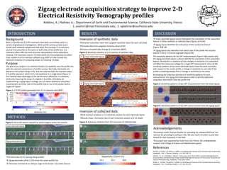
- 1. Zigzag electrode acquisition strategy to improve 2-D Electrical Resistivity Tomography profiles Robbins, A.; Plattner, A.; Department of Earth and Environmental Science, California State University, Fresno 1. austinrr@mail.fresnostate.edu; 2. aplattner@csufresno.edu INTRODUCTION METHODS RESULTS DISCUSSION Inversion of synthetic data Inversion of collected data Generate subsurface mesh with assigned resistivity values for each cell (E4D) Simulate data from assigned resistivity values (E4D) Process simulated data through 3-D inversion (BERT) E4D inversion produces a 3-D resistivity solution for each electrode layout Results show a horizontal slice of each resistivity solution at 0.5m depth Linear electrode layout cannot distinguish the orientation of the subsurface feature in either synthetic or collected data (Figures 3A & 4A) Zigzag layout identifies the orientation of the conductive feature (Figure 3B & 4B) Zigzag layout also identifies from which side of the profile the resistive feature in the 2.5-D result originates (Figure 4B) The sensitivity patterns for the ERT measurements (Figure 5 &6) explain why the zigzag electrode layout is able to identify the orientation of the subsurface feature. Sensitivity is a measure of how changes in resistivity of a subsurface cell affect the measured voltage for a single ERT measurement. Since all the sensitivity patterns of the linear electrode layout have the same symmetry with respect to the center profile, a change in resistivity on one side of the profile is indistinguishable from a change in resistivity on the other. By breaking the collective symmetry of sensitivity patterns for each measurement, the zigzag electrode layout is able to identify additional subsurface information near the profile line. Acknowledgements The authors thank Thomas Günther for providing his software BERT and Tim Johnson for providing his software E4D. We also thank Christine Liu and Alex Briand for their assistance in the field. This project was supported by funds from CSU Fresno, ASI undergraduate research and College of Science and Mathematics grants. 28 electrodes (0.5m spacing along profile) Zigzag electrodes offset 0.25m from the center profile line Electrodes oriented at an oblique angle to the known subsurface feature References Günther, T.; Rücker, C. & Spitzer, K. (2006): 3-d modeling and inversion of DC resistivity data incorporating topography - Part II: Inversion. Geophys. J. Int. 166, 506-517 Johnson, T. C., R. J. Versteeg, A. Ward, F. D. Day-Lewis, and A. Revil (2010), Improved Hydrogeophysical Characterization and Monitoring Through Parallel Modeling and Inversion of Time-domain Resistivity and Induced Polarization Data, Geophysics, 75(4), Wa27-Wa41 Rücker, C.; Günther, T. & Spitzer, K. (2006): 3-d modeling and inversion of DC resistivity data incorporating topography - Part I: Modeling. Geophys. J. Int. 166, 495-505 Figure 1: 2-D ERT profile generated from 2.5-D inversion with BERT Figure 3: Resistivity solutions of 3-D inversion of synthetic data Zigzag electrode layout Figure 4: Resistivity solutions from 3-D inversions of collected data Linear electrode layout Figure 2: Electrode layouts overlaid on aerial imagery of the site location Figure 6: Sensitivity patterns of two ERT measurements from the zigzag layout Figure 5: Sensitivity patterns of two ERT measurements from the linear layout Both 2-D profile and 3-D ERT inversions have been successfully used in a variety of geophysical investigations. While profile surveys provide quick results with relatively inexpensive field work, the ensuing 2.5-D inversions assume the subsurface is the same on both sides of the profile line. 3-D inversions often offer the most accurate interpretation of the subsurface; however, 3-D inversions require 3-D data which are more expensive to collect. Free, modern full 3-D inversion software (e.g. BERT or E4D) remove the historical limitation of computing power on inverting 3-D data. Background Purpose The goal of our project is to combine limited 3-D capability near the profile line with the ease and convenience of profile surveys. Normally, electrodes are placed on the surface along a line. And the collected data are inverted using a 2-D profile approach, which limits interpretation to a single plane (Figure 1). Our method takes advantage of the performance offered by 3-D software, while only requiring the setup of a typical 2-D profile. Ultimately, by implementing a zigzag layout strategy, we can obtain additional subsurface characteristics on either side of the profile (into or out of the poster) with a single ERT layout. A B Linear electrode layout Zigzag electrode layout