Download as PDF, PPTX


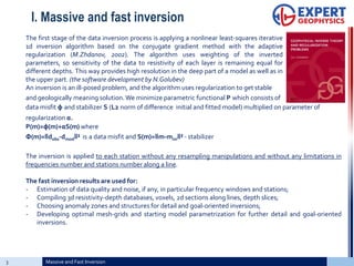
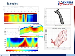
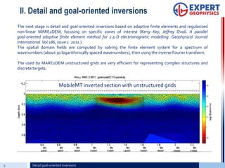
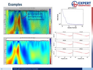
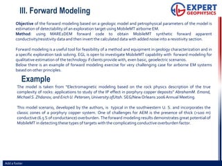
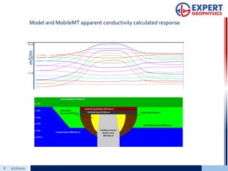


I. Massive and fast inversions provide high resolution inversion of MobileMT data into resistivity-depth models without limitations on frequency or station numbers. Results are used to assess data quality and compile databases for further analysis. II. Detail and goal-oriented inversions use adaptive finite element modeling focused on specific zones, providing more detailed models of complex structures. III. Forward modeling estimates the detectability of exploration targets using MobileMT, helping evaluate the technology's capability for specific geology.