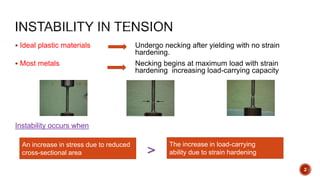
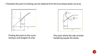
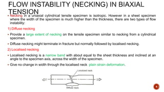
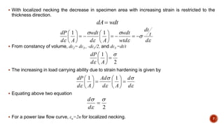
Study on Air-Water & Water-Water Heat Exchange in a Finned Tube Exchanger
Necking
1.
2. Ideal plastic materials Undergo necking after yielding with no strain
hardening.
Most metals Necking begins at maximum load with strain
hardening increasing load-carrying capacity
Instability occurs when
>
An increase in stress due to reduced
cross-sectional area
The increase in load-carrying
ability due to strain hardening
2
3. The condition of instability, which leads to localized deformation is defined by dP=0.
From the constancy of volume relationship,
From instability condition
So that at a point of tensile instability
3
4. Therefore the point of necking can be obtained from the true stress-strain curve by
Finding the point on the curve
having a sub tangent of unity
The point where the rate of strain
hardening equals the stress
4
5. The maximum load can be determined from Considère’s construction when the stress-strain
curve is plotted in terms of true stress σ and conventional strain e.
Let point A represent a negative strain of 1.
A line drawn from point ‘A’ which is tangent to the stress-strain curve will give maximum load with
the slope of σ/(1+e).
This strain is the true uniform strain εu.
Considère’s construction for the
determination of the point maximum load
5
6. Necking in a uniaxial cylindrical tensile specimen is isotropic. However in a sheet specimen
where the width of the specimen is much higher than the thickness, there are two types of flow
instability:
1) Diffuse necking
Provide a large extent of necking on the tensile specimen similar to necking from a cylindrical
specimen.
Diffuse necking might terminate in fracture but normally followed by localised necking.
2) Localised necking
Localised necking is a narrow band with about equal to the sheet thickness and inclined at an
angle to the specimen axis, across the width of the specimen.
Give no change in width through the localised neck plain strain deformation.
6
7. With localized necking the decrease in specimen area with increasing strain is restricted to the
thickness direction.
From constancy of volume, dε2= dε3= -dε1/2, and dε3 =dt/t
The increasing in load carrying ability due to strain hardening is given by
Equating above two equation
For a power law flow curve, εu=2n for localized necking.
d
t
dt
wtd
wdt
Ad
wdt
Ad
dP
11
2
1
Ad
dP
d
d
Ad
Ad
Ad
dP
11
2
d
d
7
wdtdA
8. Necking introduces a complex triaxial state of stress in the necked region. The neck region is in
effect a mild notch.
The average true stress at necking, which is much higher than the stress would be required to
cause a normal plastic flow due to stresses in width and thickness directions.
(a) Geometry of necked region
(b) Stress acting on element at point ‘O’ 8
9. Bridgman made a mathematical analysis which provides a correction to the average axial stress
to compensate for the introduction of transverse stresses.
This analysis was based on the following assumptions:
a) The contour of the neck is approximated by the arc of a circle.
b) The cross section of the necked region remains circular throughout the test.
c) The von Mises’ criterion for yielding applies.
d) The strains are constant over the cross section of the neck.
According to Bridgman’s analysis, the uniaxial flow stress corresponding to that which would
exist in the tension test if necking had not introduced triaxial stresses is
where, (σx)avg is the measured stress in the axial direction,
R is the radius of curvature of the neck
a is the linear distance.
RaaR
x avg
2/1ln/21
9
10. Measured elongation in tension specimen depends on the gauge length or cross-sectional
area.
The total extension consists of two components, the uniform extension up to necking and the
localized extension once necking begins.
The extent of uniform extension will depend on the Metallurgical condition of the material
(through n) and the specimen size and shape on the development of necking.
The shorter the gauge length the greater the effect of
localized deformation at necking on total elongation
Variation of local elongation with position along gauge
length of tensile specimen
10
11. The extension of a specimen at fracture can be expressed by
Where, α is the local necking extension
euL0 is the uniform extension
The tensile elongation then is given by
According to Barba’s law, and the elongation equation is
LeLL uf 00
e
LL
LL
e u
f
f
00
0
A0
e
L
A
e uf
0
0
11
12. Dimensional relationships of tensile specimens for sheet and round
specimens
Elongation depends on the original gauge length L0. The shorter gauge length the greater the
percentage of elongation.
12
13. Difference between % elongation and reduction of area
% Elongation:
% Elongation is chiefly influenced by uniform elongation and thus it is dependent on the strain-
hardening capacity of the material.
Reduction of area:
Reduction of area is more a measure of the deformation required to produce failure and its chief
contribution results from the necking process.
Because of the complicated stress state in the neck, values of reduction of area are dependent
on specimen geometry and deformation behaviour, and they should not be taken as true
material properties.
Reduction of area is the most structure-sensitive ductility parameter and is useful in detecting
quality changes in the materials.
13
14. Strain rate is applied to the specimen can have an important influence on the stress.
Strain rate unit is s-1.
14
dt
d
Flow stress dependence of
strain rate and temperature
15. The crosshead velocity is v=dL/dt. The rate expressed in terms of conventional linear starin is
The true strain rate is given by
The above equation indicates that for a constant crosshead speed the true strain rate will
decreases as the specimen elongates.
The true strain rate is related to the conventional strain rate by the following equation:
15
e
00
00 1/L-L
L
v
dt
dL
Ldt
Ld
dt
de
e
L
v
dt
dL
Ldt
d
dt
d
1L/Lln 0
e
e
dt
de
edt
de
L
L
L
v
11
10
16. To maintain a constant true strain rate using open loop control the deformation velocity must
increases in proportion to the increases in the length of the specimen as
For deformation occurring at constant volume a constant true strain rate is obtained if the
specimen area changes as
A general relationship between flow stress and strain rate, at constant strain and temperature as
Where m is strain rate sensitivity.
16
tLv exp0
tAA exp0
12
12
12
12
,, /log
/log
loglog
loglog
log
log
ln
ln
TT
m
17. The velocity dislocation motion was very strongly dependent on stress according to
Strain rate is related to velocity of mobile dislocation by
Therefore,
If there is no change in the mobile dislocation density with increasing stress, m’=1/m.
17
'm
Av
bv
'
ln
ln
m
v
ln
ln
ln
ln
ln
ln1
v
m
ln
ln1
'
m
m
18. Strain rate sensitivity (m) indicates any changes in deformation behaviour. Measurement of
strain rate sensitivity can be linked to dislocation concept.
High strain rate sensitivity is a characteristic of superplastic metals and alloys.
From the definition of true strain rate
Combining above two equations
The above equation states that so long as m is less than 1 the smaller the cross sectional area,
the more rapidly the area is reduced.
18
m
C
A
P
or
mm
AC
P
/1/1
1
dt
dA
Adt
dL
L
11
m
m
C
P
AA
dt
dA
/1
/11
mm
m
AC
P
dt
dA
/1
/1
1
19. When m=1 the deformation is Newtonian viscous and dA/dt is independent of ‘A’ and any neck is
simply preserved during elongation and does not propagate inward. As ‘m’ approaches unity, the
rate of growth of incipient necks is drastically reduced.
19
Dependence of tensile
elongation on strain-rate
sensitivity
Dependence of rate of decrease
of area on cross sectional area for
different values of ‘m’
20. Notch tensile test is used to evaluate notch sensitivity (the tendency for reduced tensile ductility
in the presence of a triaxial stress field and steep stress gradients).
Notch tension specimens have been used for fracture mechanics measurements.
Notch tensile specimen
60° notch with a root radius of 0.025 mm or less introduced into a round (circumferential notch)
or a flat (double-edge notch) tensile specimen.
The cross-sectional area under the notch root is one-half of the unnotched area.
20
Notch tensile specimen Stress distribution around tensile notches
21. Notch strength
Notch strength is defined as the maximum load divided by the original cross-sectional area at
the notch.
Due to the constraint at the notch, the notch strength is higher than the tensile strength of the
unnotched specimen.
Notch-strength ratio (NSR) detects notch brittleness (high notch sensitivity) from
If the NSR is < 1, the material is notch brittle.
21
specimen)unnotchedforstrength(tensile
load)maximumatspecimennotched(for
Su
Snet
NSR