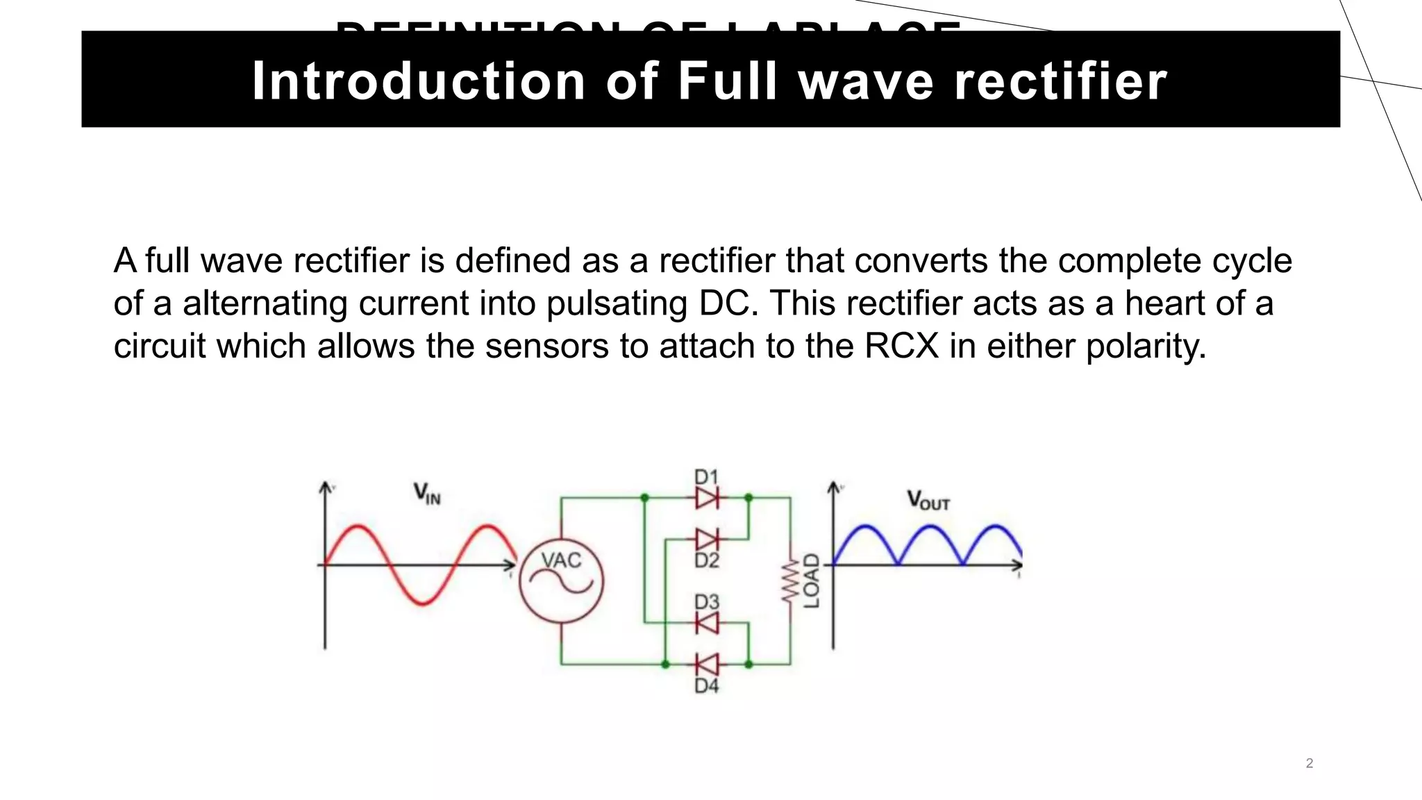
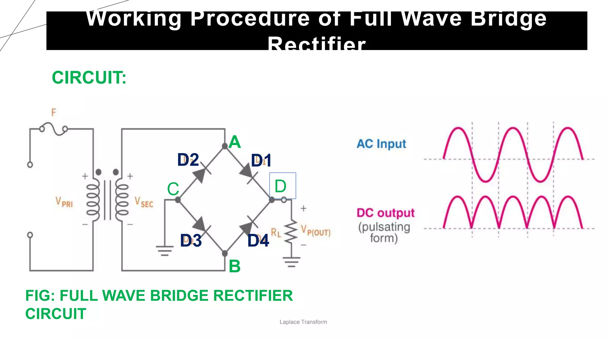
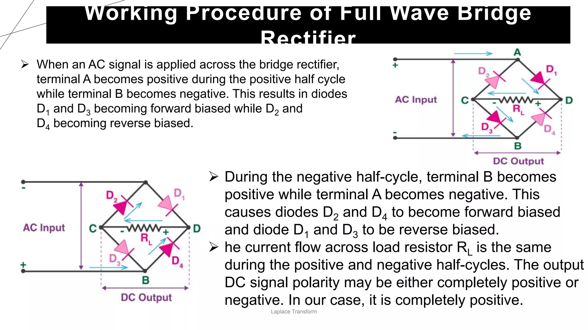
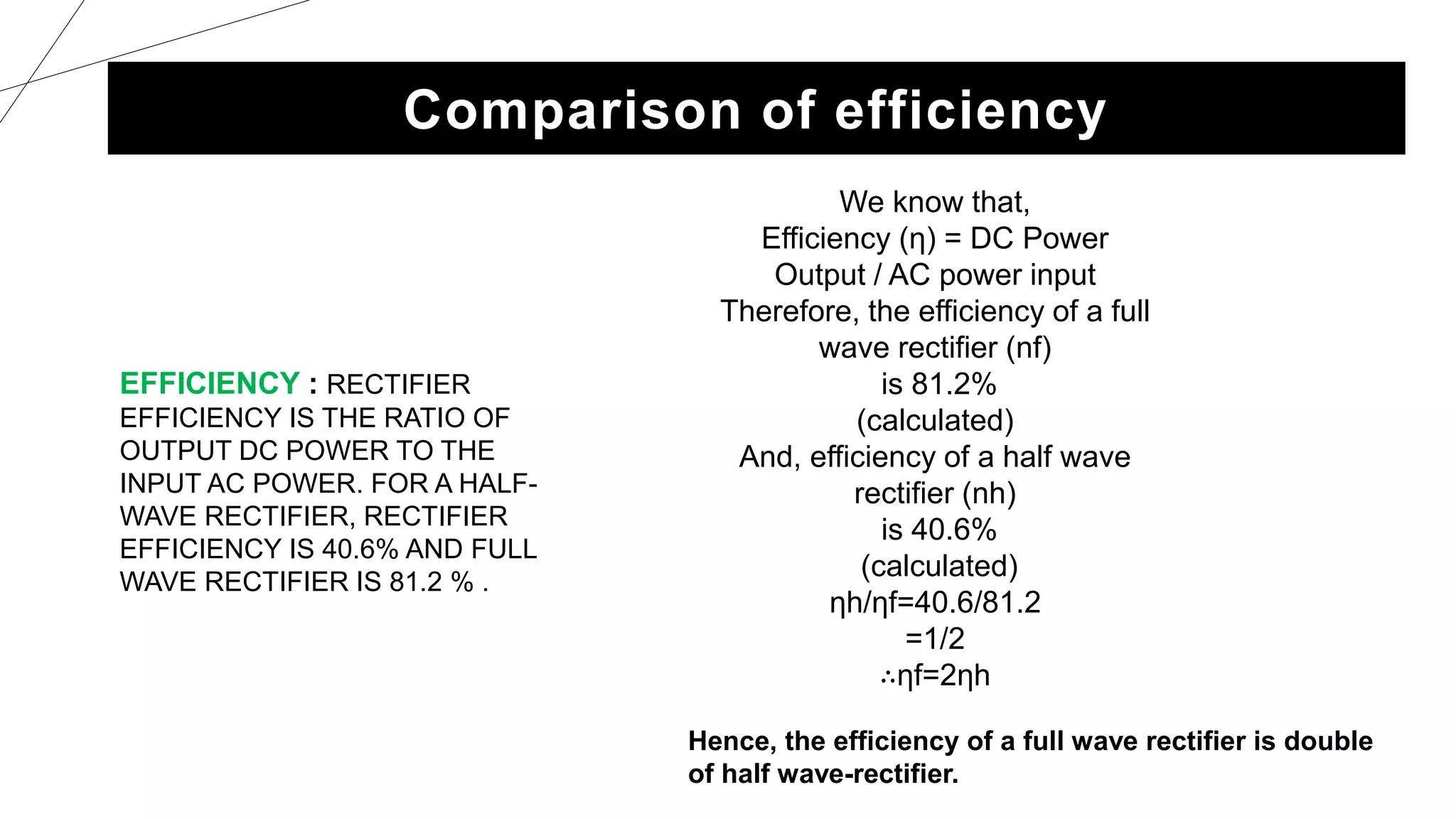
2. 2
DEFINITION OF LAPLACE
TRANSFORM
Introduction of Full wave rectifier
A full wave rectifier is defined as a rectifier that converts the complete cycle
of a alternating current into pulsating DC. This rectifier acts as a heart of a
circuit which allows the sensors to attach to the RCX in either polarity.
3. 3
Full Wave Rectifier is a diode circuit which is used to transform the complete
cycle of Alternating Voltage to Direct Voltage .
In full wave rectification, current flows through the load in the same direction
for the complete cycle of input AC Supply.
Types of Full Wave Rectifiers:
1.Centre Tap Full Wave Rectifier.
2. Full Wave Bridge Rectifier.
Classification of full wave rectifier
4. 4
Center Tapped Full Wave Rectifier
A center tapped full wave rectifier is a type of rectifier which uses a
center tapped transformer and two diodes to convert the complete
AC signal into DC signal.
The center tapped full wave rectifier is made up of an AC source, a
center tapped transformer, two diodes, and a load resistor.
5. During the positive half cycle, diode D1 is forward
biased as it is connected to the top of the secondary
winding while diode D2 is reverse biased as it is
connected to the bottom of the secondary winding.
Due to this, diode D1 will conduct acting as a short
circuit and D2 will not conduct acting as an open
circuit.
During the negative half cycle, the diode D1 is reverse
biased and the diode D2 is forward biased because
the top half of the secondary circuit becomes
negative and the bottom half of the circuit becomes
positive. Thus in a full wave rectifiers, DC voltage is
obtained for both positive and negative half cycle.
5
Working Procedure of Center Tapped Full Wave Rectifier
6. Laplace Transform
Full Wave Bridge Rectifier
BASIC COMPONENTS OF A FULL-WAVE BRIDGE
RECTIFIER
Four diodes arranged in a "bridge" configuration
Transformer used to step down inputted higher
voltage to suitable lower voltage.
Load resistor to smooth out the output DC voltage
Wires , resistance etc.
8. Laplace Transform
Working Procedure of Full Wave Bridge
Rectifier
When an AC signal is applied across the bridge rectifier,
terminal A becomes positive during the positive half cycle
while terminal B becomes negative. This results in diodes
D1 and D3 becoming forward biased while D2 and
D4 becoming reverse biased.
During the negative half-cycle, terminal B becomes
positive while terminal A becomes negative. This
causes diodes D2 and D4 to become forward biased
and diode D1 and D3 to be reverse biased.
he current flow across load resistor RL is the same
during the positive and negative half-cycles. The output
DC signal polarity may be either completely positive or
negative. In our case, it is completely positive.
10. We know that,
Efficiency (η) = DC Power
Output / AC power input
Therefore, the efficiency of a full
wave rectifier (nf)
is 81.2%
(calculated)
And, efficiency of a half wave
rectifier (nh)
is 40.6%
(calculated)
ηh/ηf=40.6/81.2
=1/2
∴ηf=2ηh
Comparison of efficiency
EFFICIENCY : RECTIFIER
EFFICIENCY IS THE RATIO OF
OUTPUT DC POWER TO THE
INPUT AC POWER. FOR A HALF-
WAVE RECTIFIER, RECTIFIER
EFFICIENCY IS 40.6% AND FULL
WAVE RECTIFIER IS 81.2 % .
Hence, the efficiency of a full wave rectifier is double
of half wave-rectifier.
11. Advantage of full-wave rectifier
• The rectifying efficiency of full wave rectifiers is higher than that
of half-wave rectifiers. Consequently, they are more efficient at
converting AC into DC.
• Compared to half-wave rectifiers, full wave rectifiers have a
lower ripple factor.
• In the process of rectification, there is no waste of voltage
signal, which allows them to have low power loss.
• Full wave bridge rectifiers have the advantage of not requiring a
special center-tapped transformer, which allows them to reduce
their size and cost.
12. 12
Disadvantages of full-wave rectifier
• More complicated than half-wave rectifier.
• It requires more diodes, two for center tap rectifier and four for
bridge rectifier.
• The cost of the center tap transformer is high.
• The DC output is small as using each of diode utilized only one-half
of the transformer secondary voltages.
• When a small voltage is required to be rectified, the full-wave
rectifier circuit is not suitable.