Download as PDF, PPTX
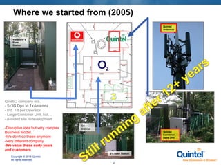
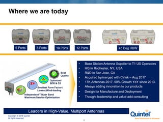
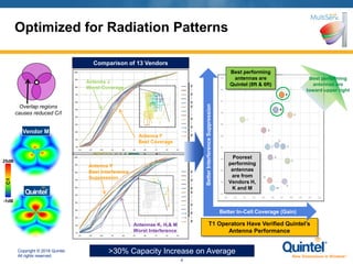

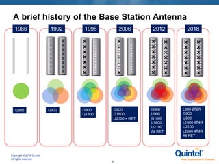

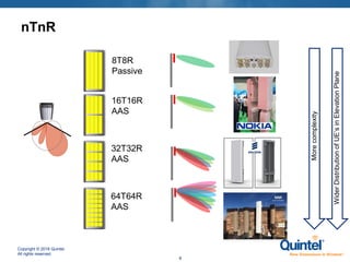
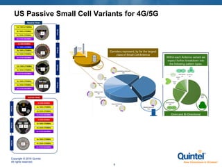
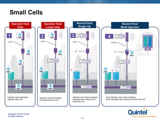
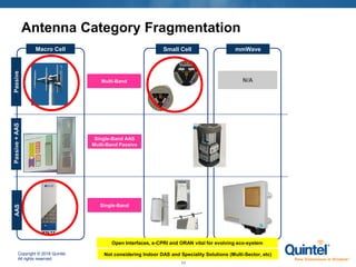
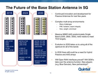
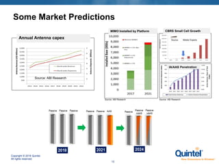
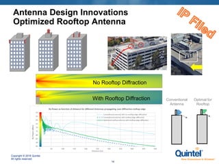


The document presents an overview of advancements in base station antennas for 5G technology, highlighting Quintel's evolution from early 3G solutions to their current leadership in multi-port antennas and performance improvements. It discusses the company's growth, innovative products, and the performance comparisons against other vendors, emphasizing the optimization for wind loading and interference suppression. Additionally, it outlines future trends and challenges in antenna technology as it progresses towards 2030.