Downloaded 175 times


![Propagation Models19
MAPL
Propagation
Model
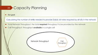
Cell
Radius
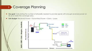
An RF propagation model is a mathematical formula used to characterize the radio wave
propagation between the transmitter and receiver.
Okumura-Hata: [150MHz,1500MHz]
hms & hb are the UE and eNB heights, R is the separation between Tx and Rx antennas
By substituting PL by MAPL in the previous equation we get the cell Radius
COST231-Hata: [1500MHz,2000MHz]](https://image.slidesharecdn.com/ltecellplanning-170508051224/85/LTE-Cell-Planning-19-320.jpg)


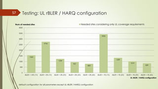
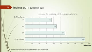
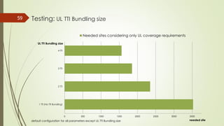
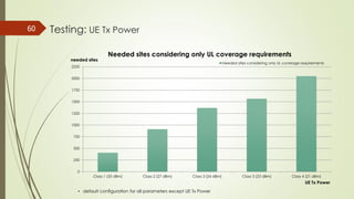
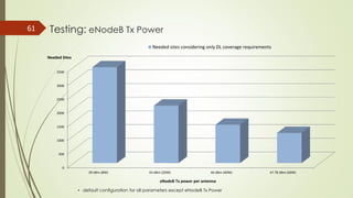
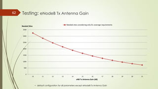
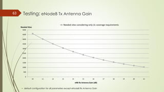
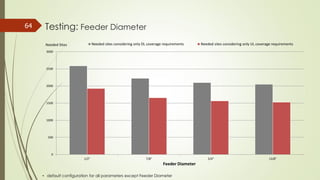
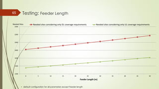
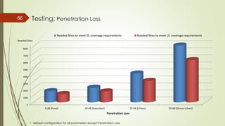
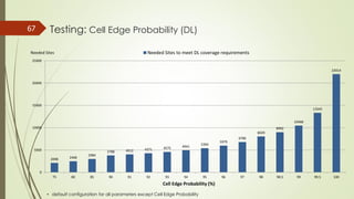
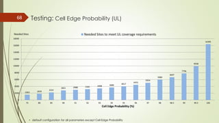


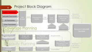
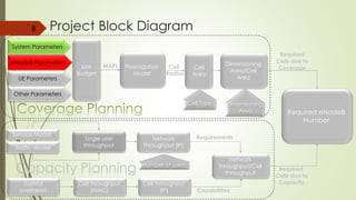
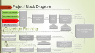
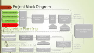
The document presents a comprehensive planning tool focused on LTE network design, detailing key parameters, project phases, coverage planning, and capacity calculations. It encompasses various topics including radio propagation models, link budget calculations, and testing methodologies, aimed at optimizing the number of required eNodeBs to meet coverage and capacity demands. Additionally, it highlights necessary enodeb parameters, system characteristics, and performance metrics essential for effective network planning.