Downloaded 1,471 times
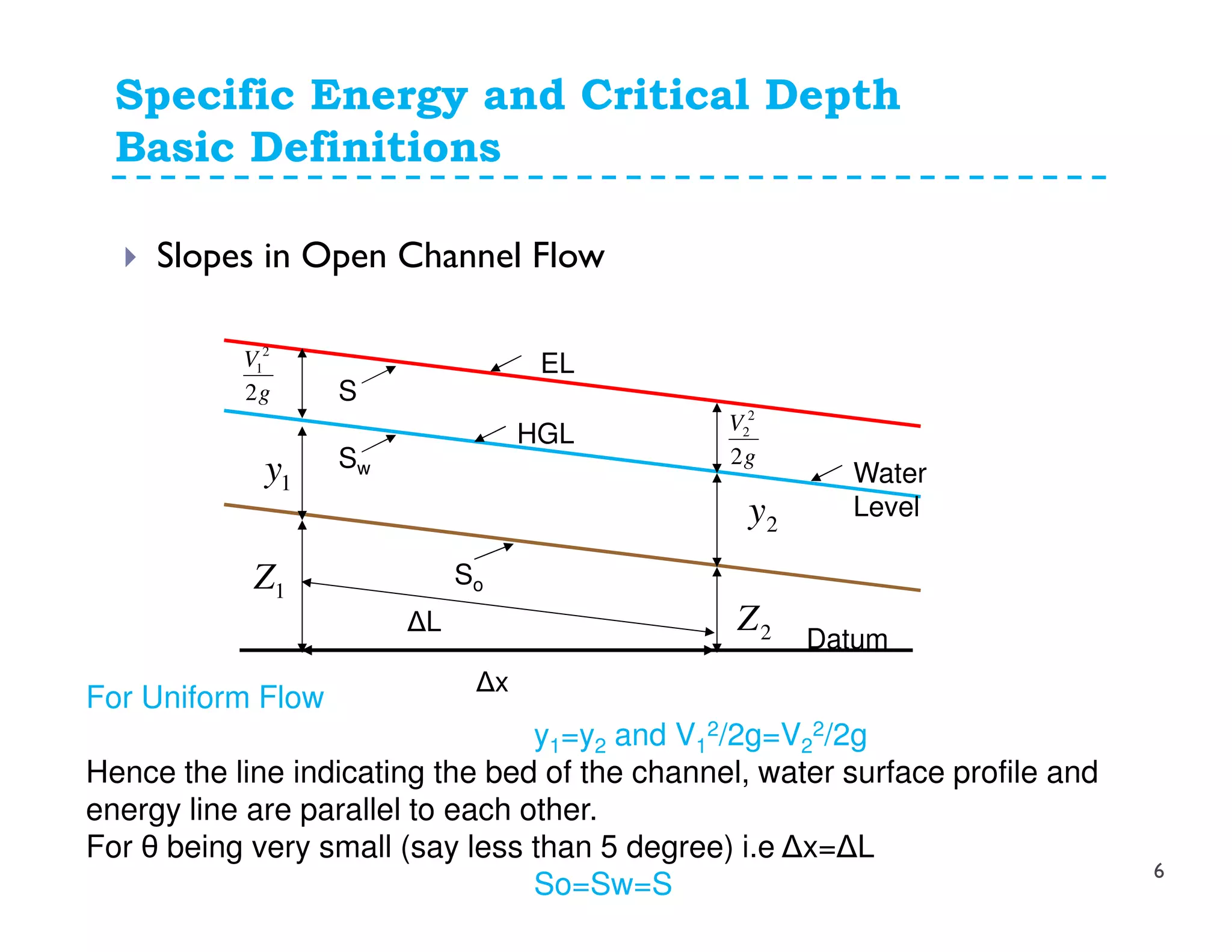
![Slopes in Open Channel Flow
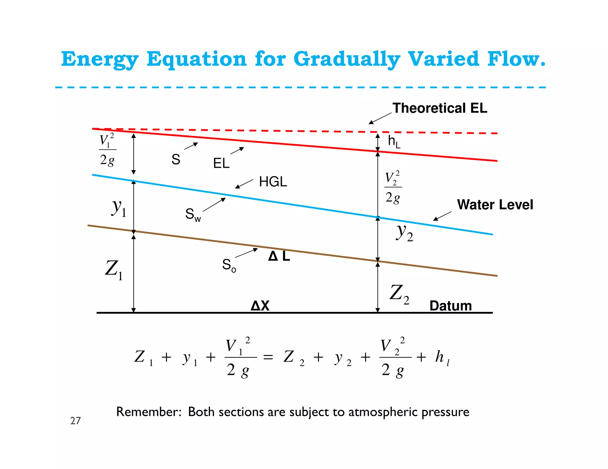
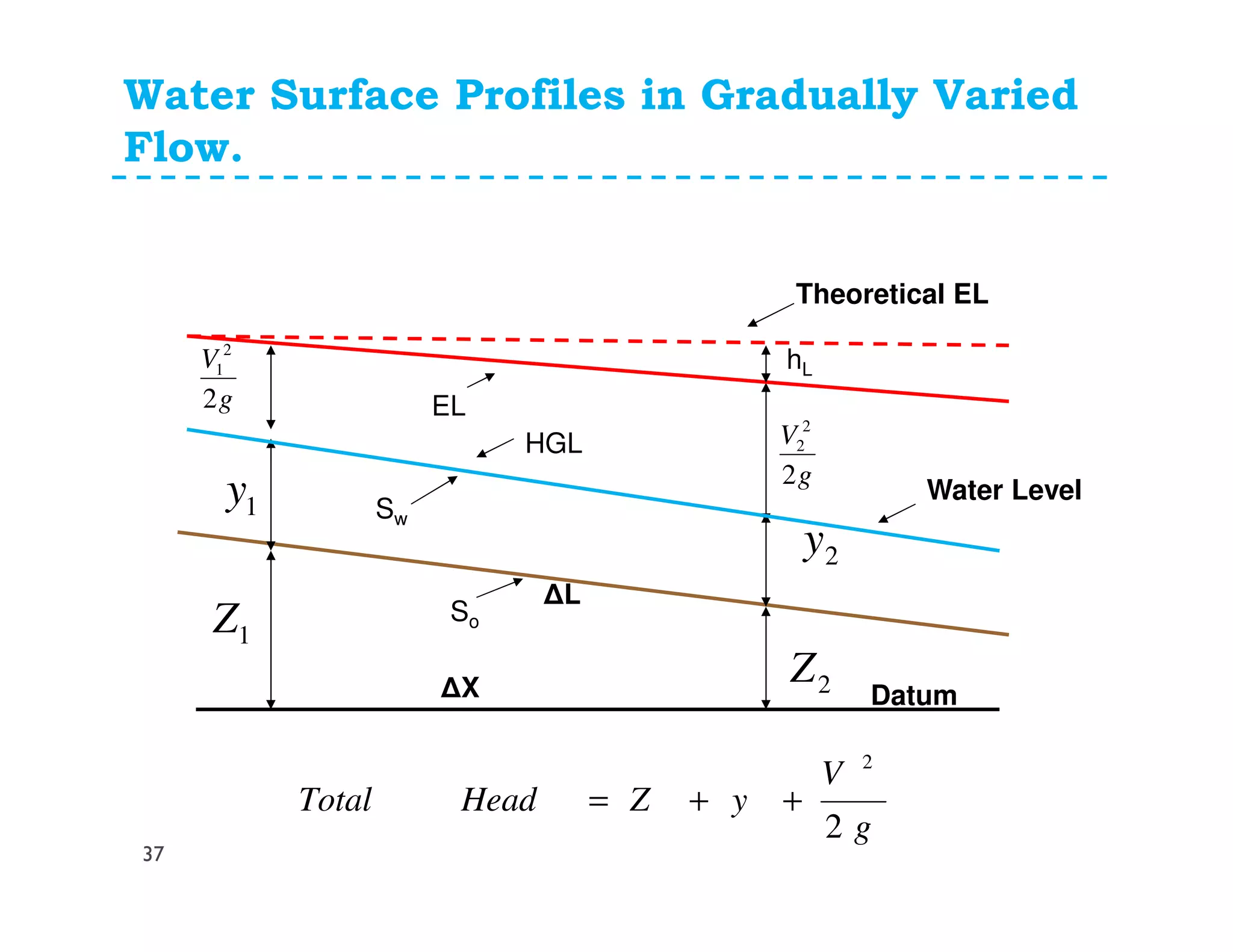
So= Slope of Channel Bed = (Z1-Z2)/(Δx)= -ΔZ/Δx
Sw= Slope of Water Surface= [(Z1+y1)-(Z2+y2)]/Δx
S= Slope of Energy Line= [(Z1+y1+V1
2/2g)-(Z2+y2+V2
2/2g)]/Δx
= hl/ΔL
1Z
g
V
2
2
1
Datum
So
1y
2Z
g
V
2
2
2
2y
HGL
EL
Water
Level
Sw
S
∆L
∆x
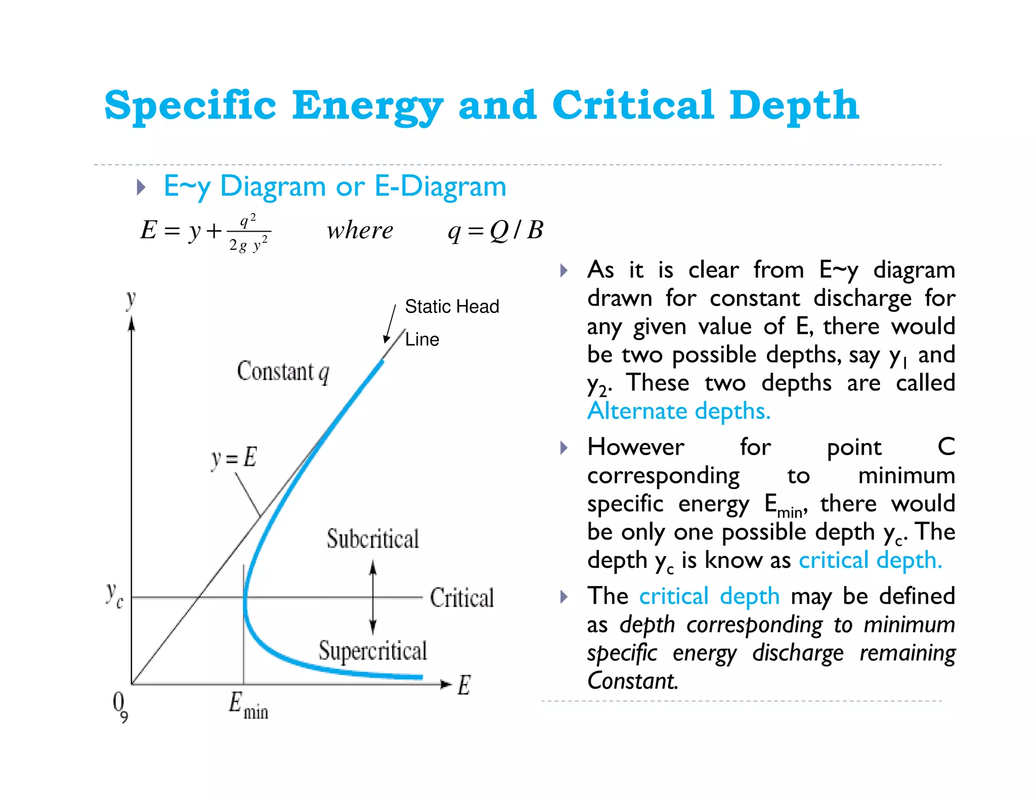
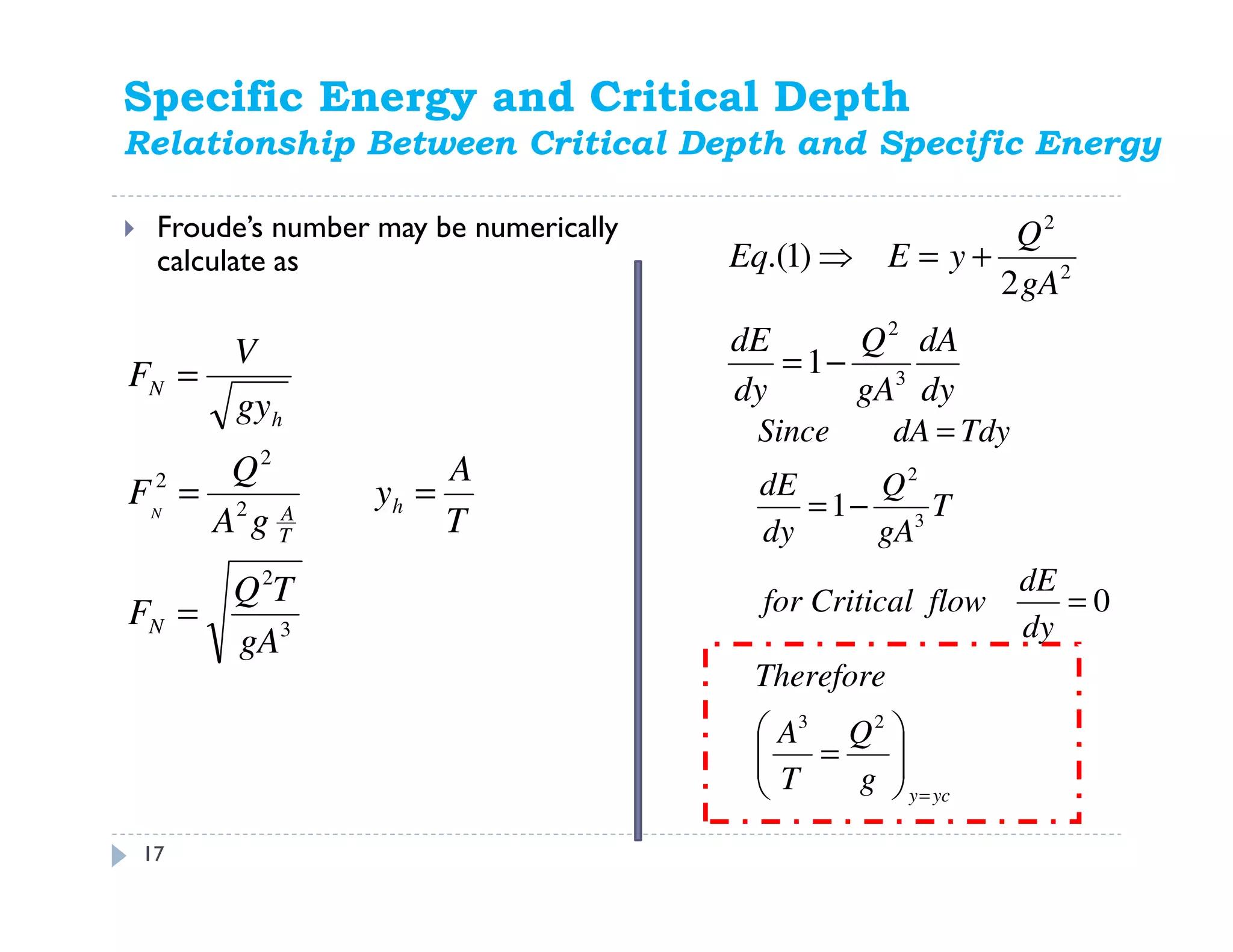
Specific Energy and Critical Depth
Basic Definitions
5](https://image.slidesharecdn.com/part-ii-openchannels-150316011348-conversion-gate01/75/Part-ii-open-channels-5-2048.jpg)
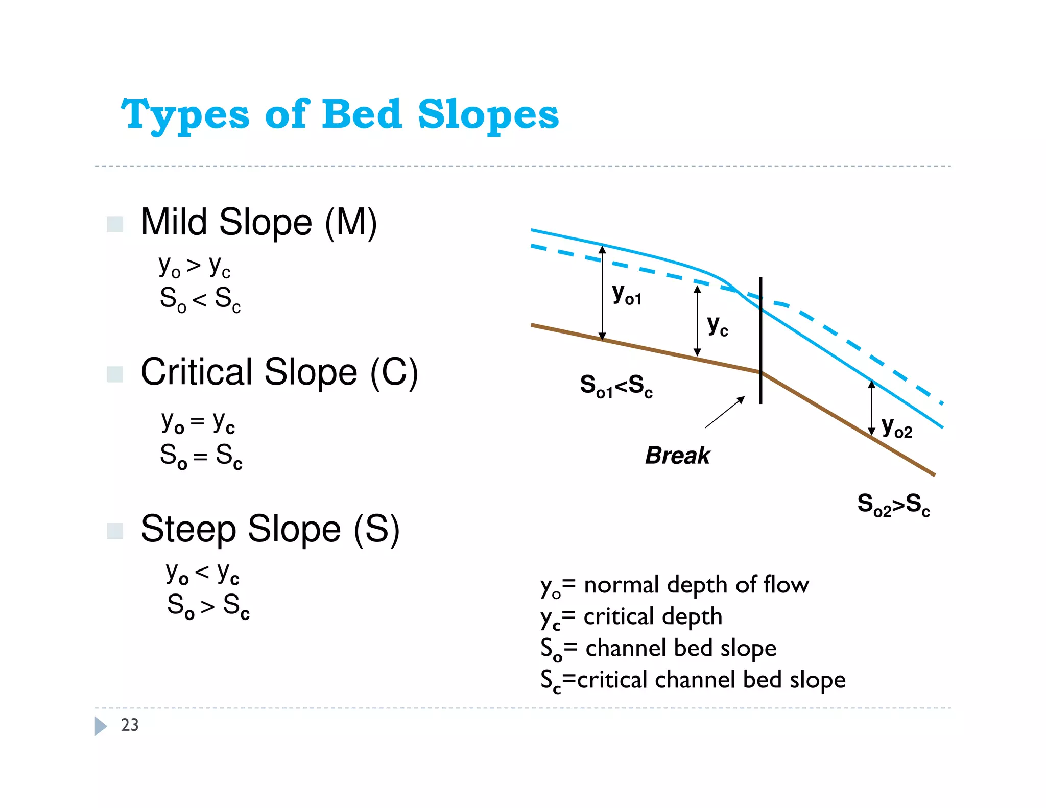
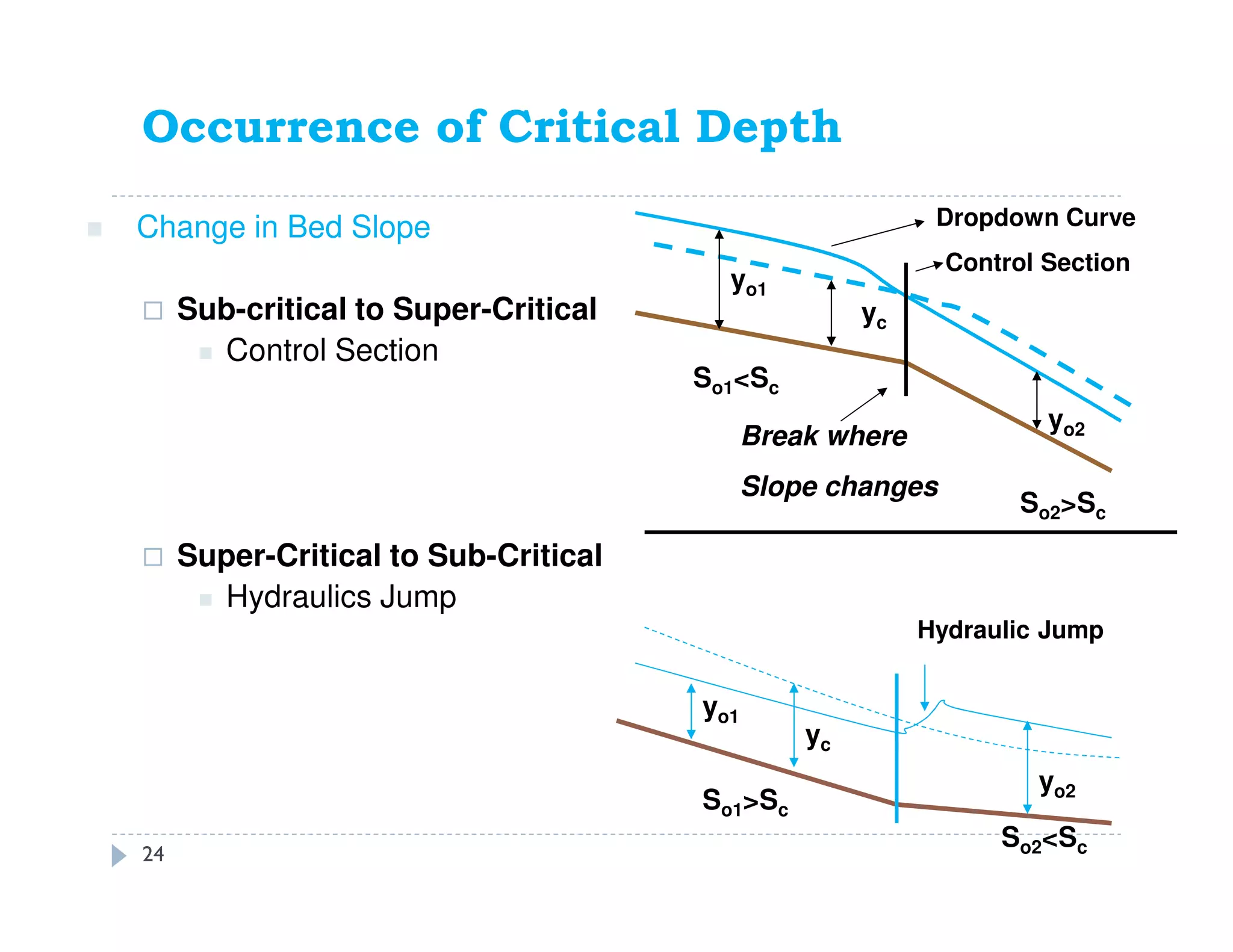
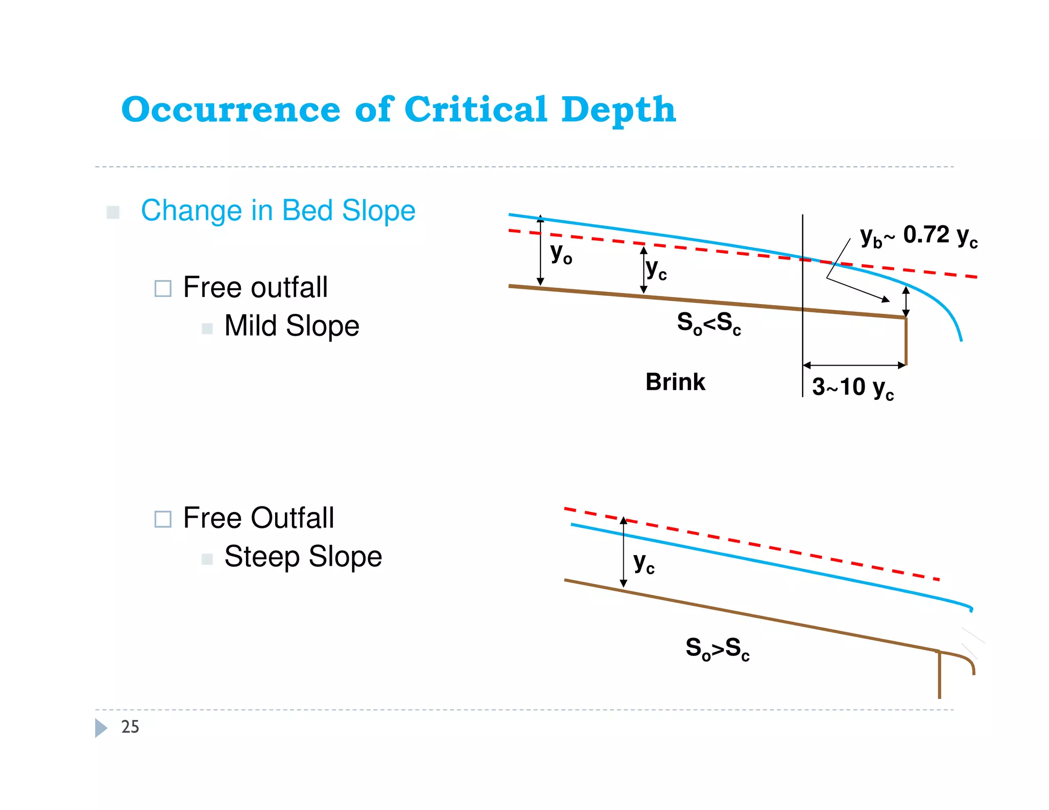
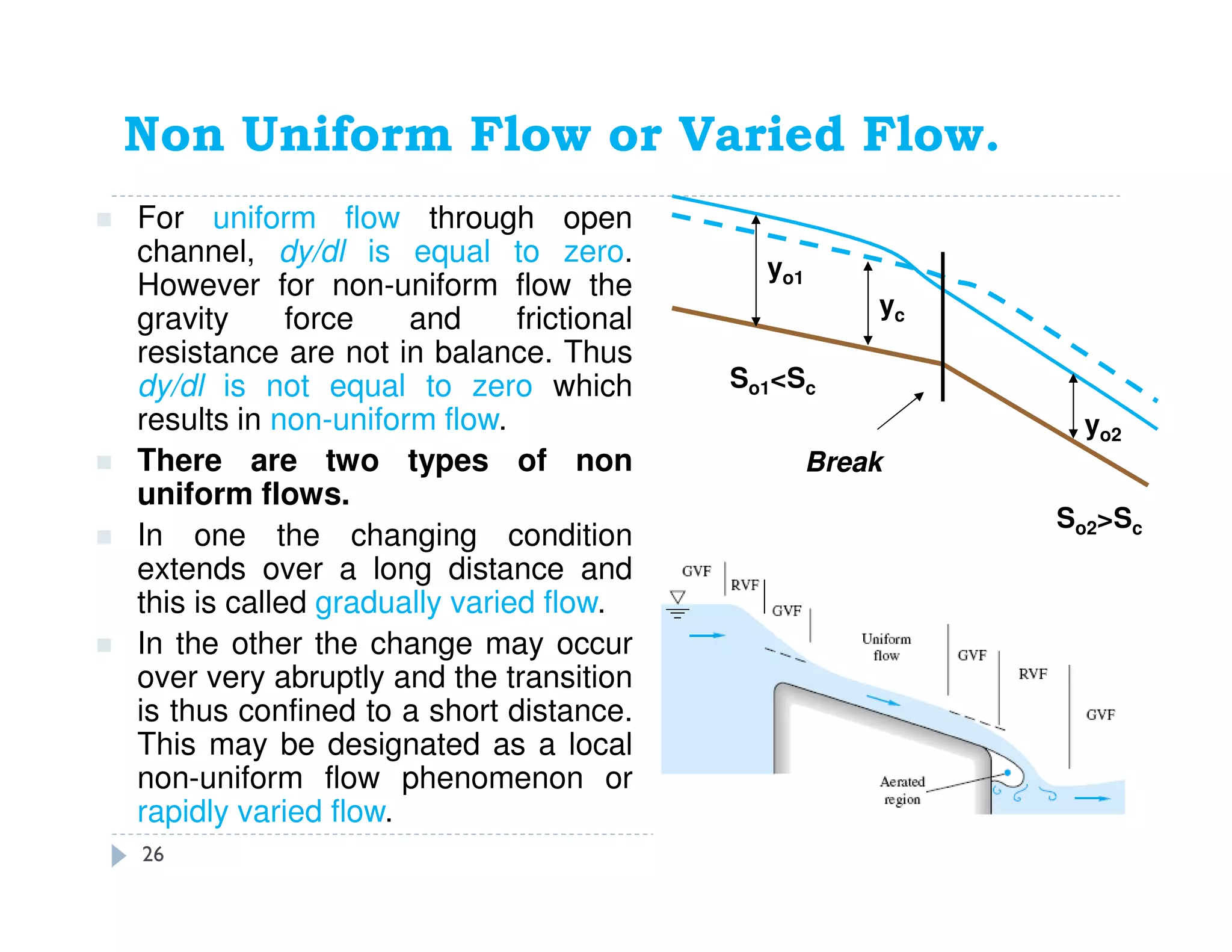
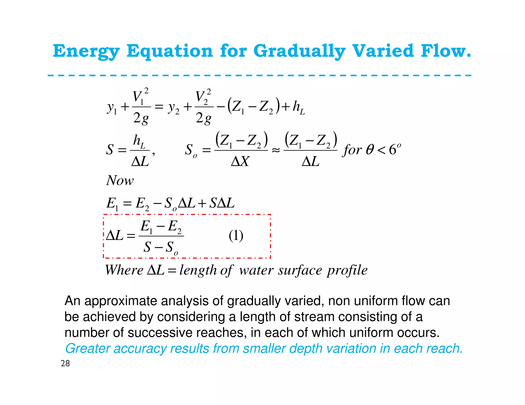
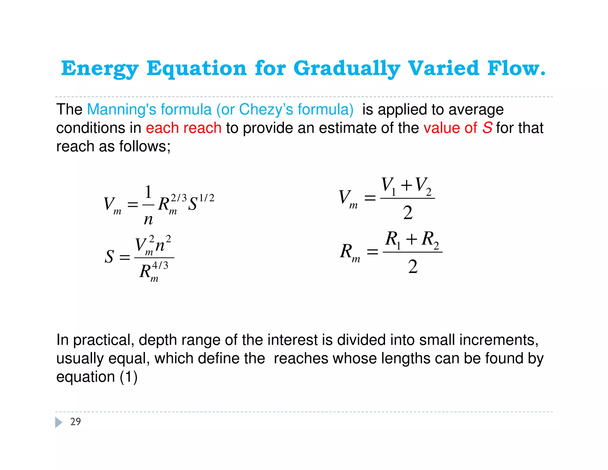

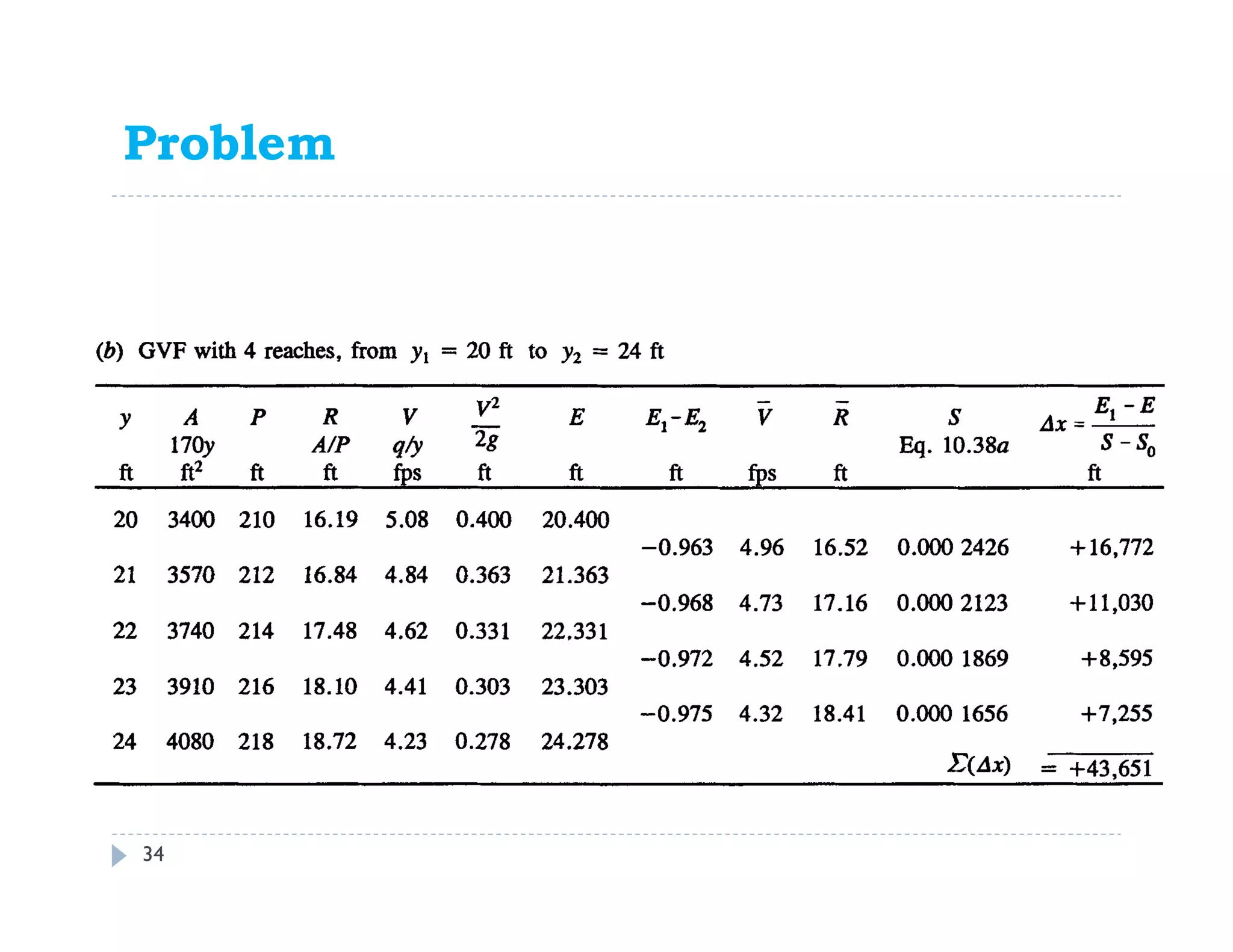
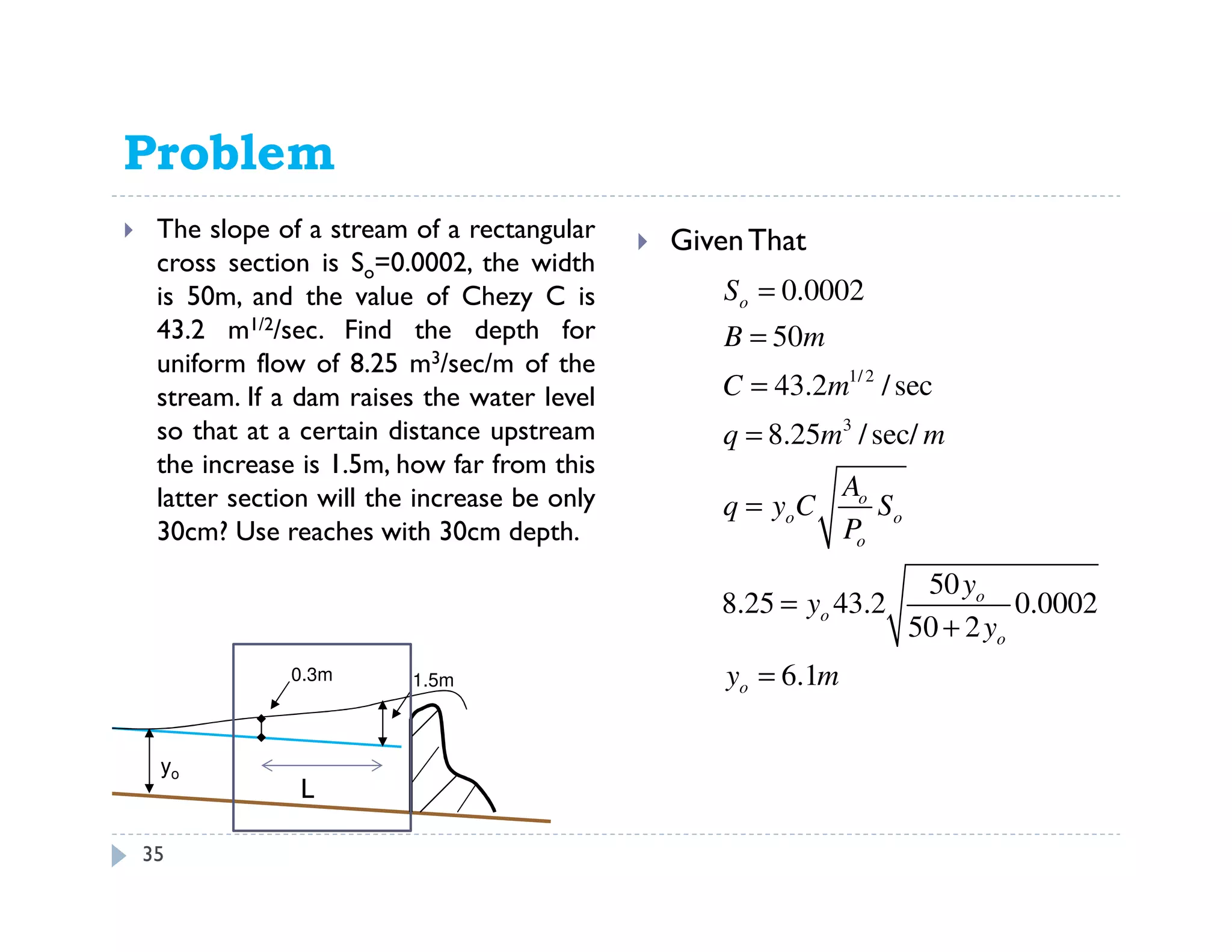
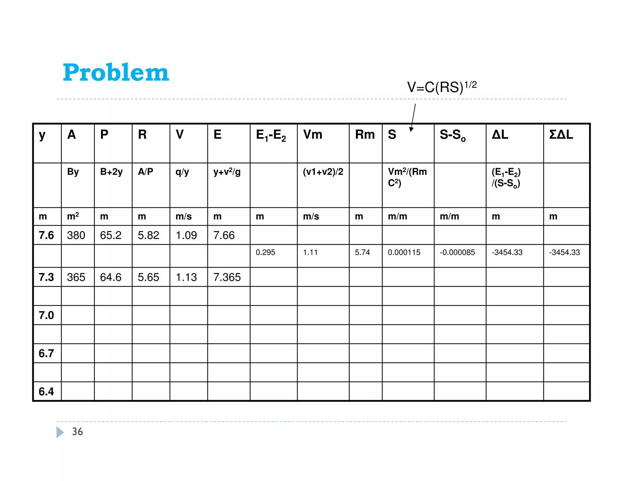
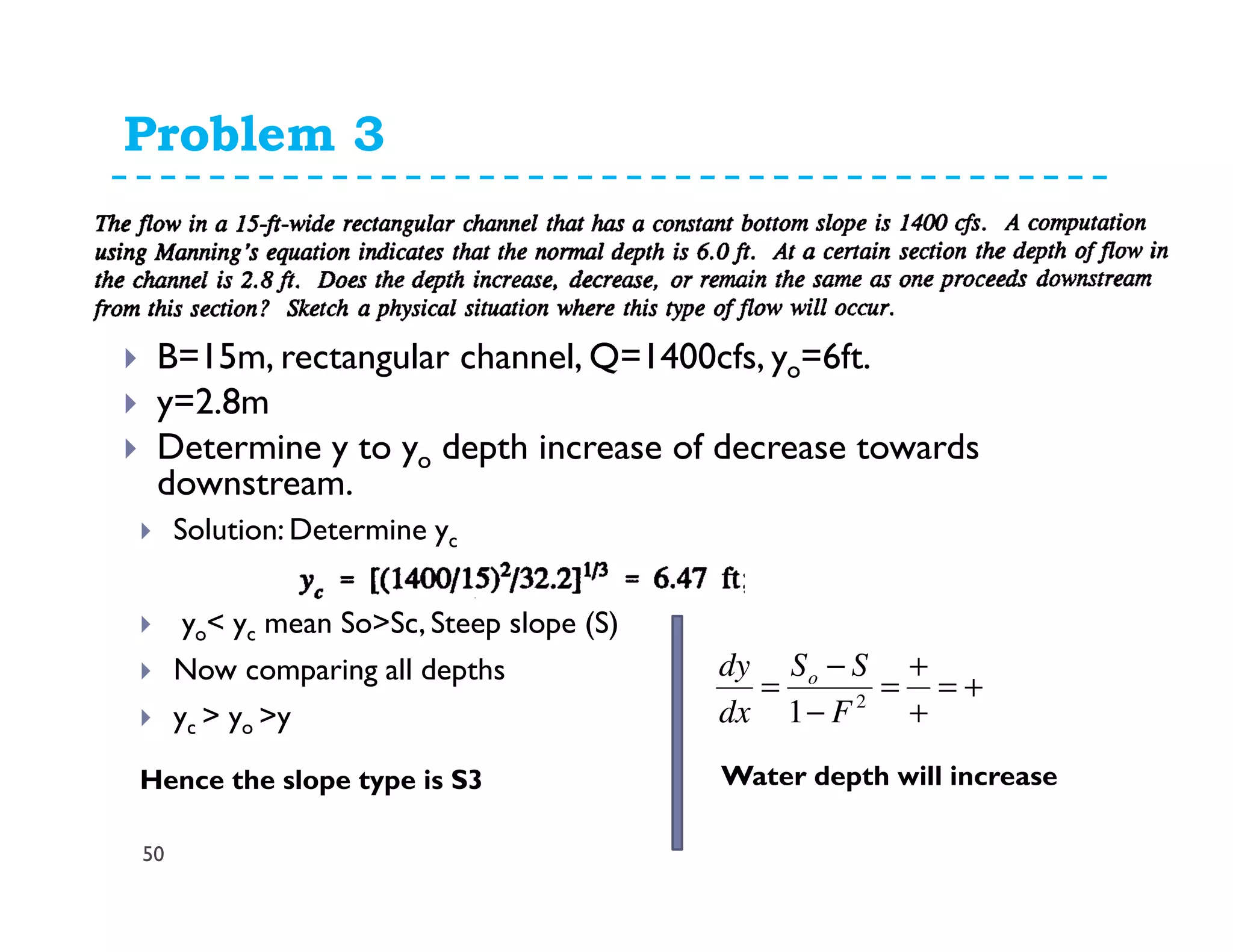

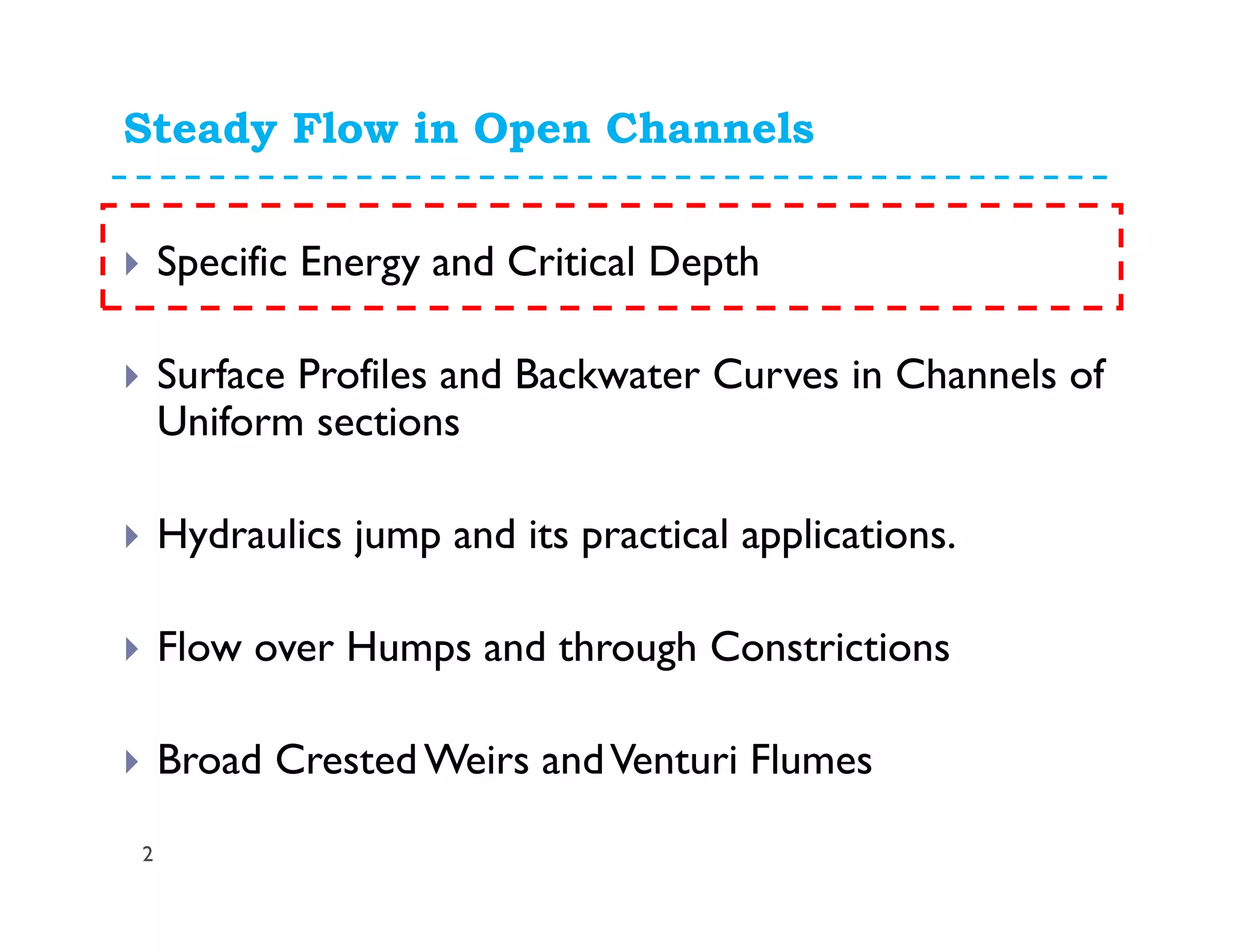
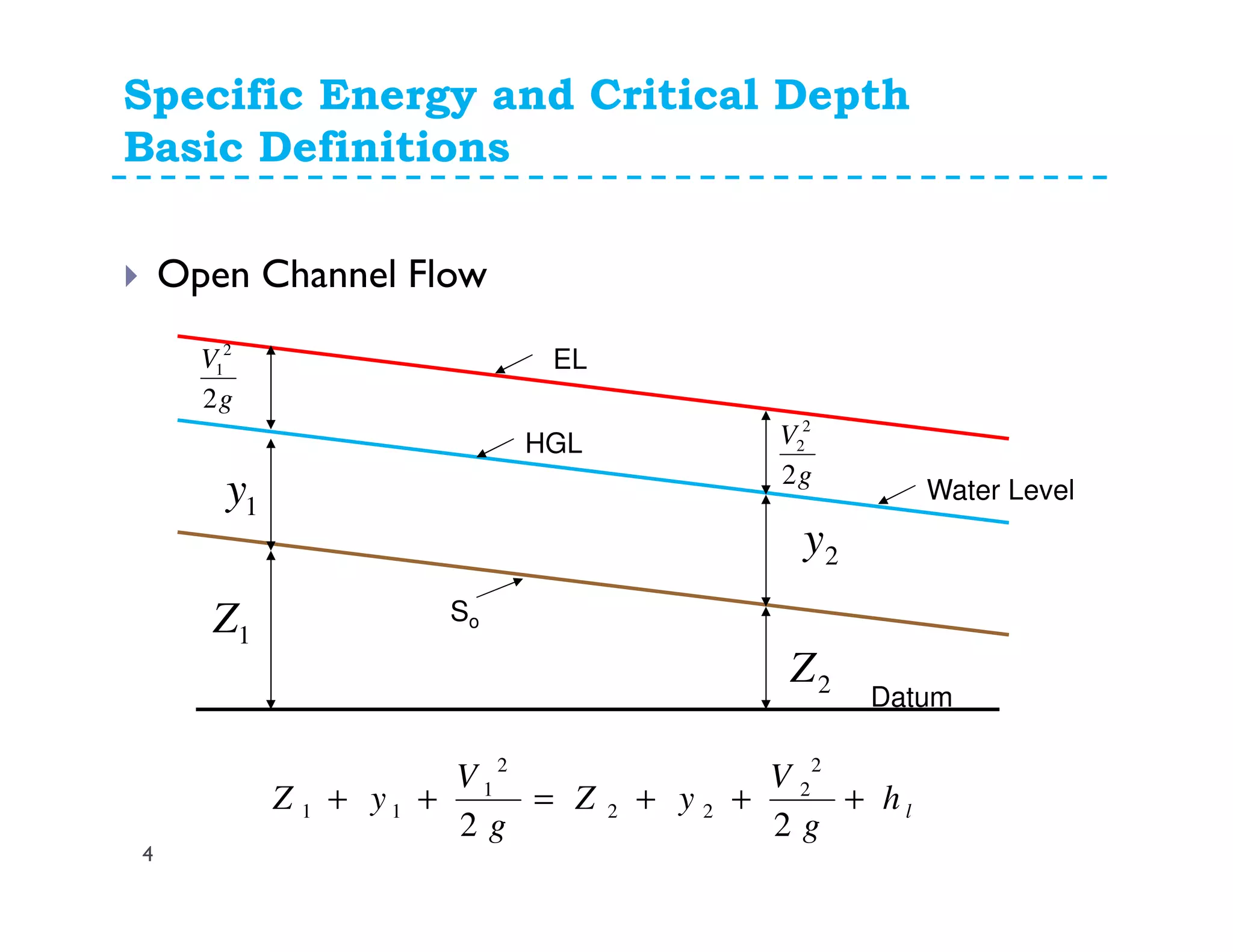
This document discusses open channel hydraulics and specific energy. It defines key terms like head, energy, hydraulic grade line, energy line, critical depth, Froude number, specific energy, and gradually varied flow. It explains the concepts of critical depth, alternate depths, and how specific energy relates to critical depth for rectangular and non-rectangular channels. It also discusses surface profiles, backwater curves, types of bed slopes, occurrence of critical depth with changes in bed slope, and the energy equation for gradually varied flow. An example problem is included to demonstrate calculating distance between depths for gradually varied flow.


![11. Silt Theories [Lacey's Theory].pdf](https://cdn.slidesharecdn.com/ss_thumbnails/11-230714062706-5eed0a09-thumbnail.jpg?width=640&height=640&fit=bounds)


![Engineering Economics: Solved exam problems [ch1-ch4]](https://cdn.slidesharecdn.com/ss_thumbnails/solvedexamproblemsch1-ch4-200220070043-thumbnail.jpg?width=640&height=640&fit=bounds)