Downloaded 153 times
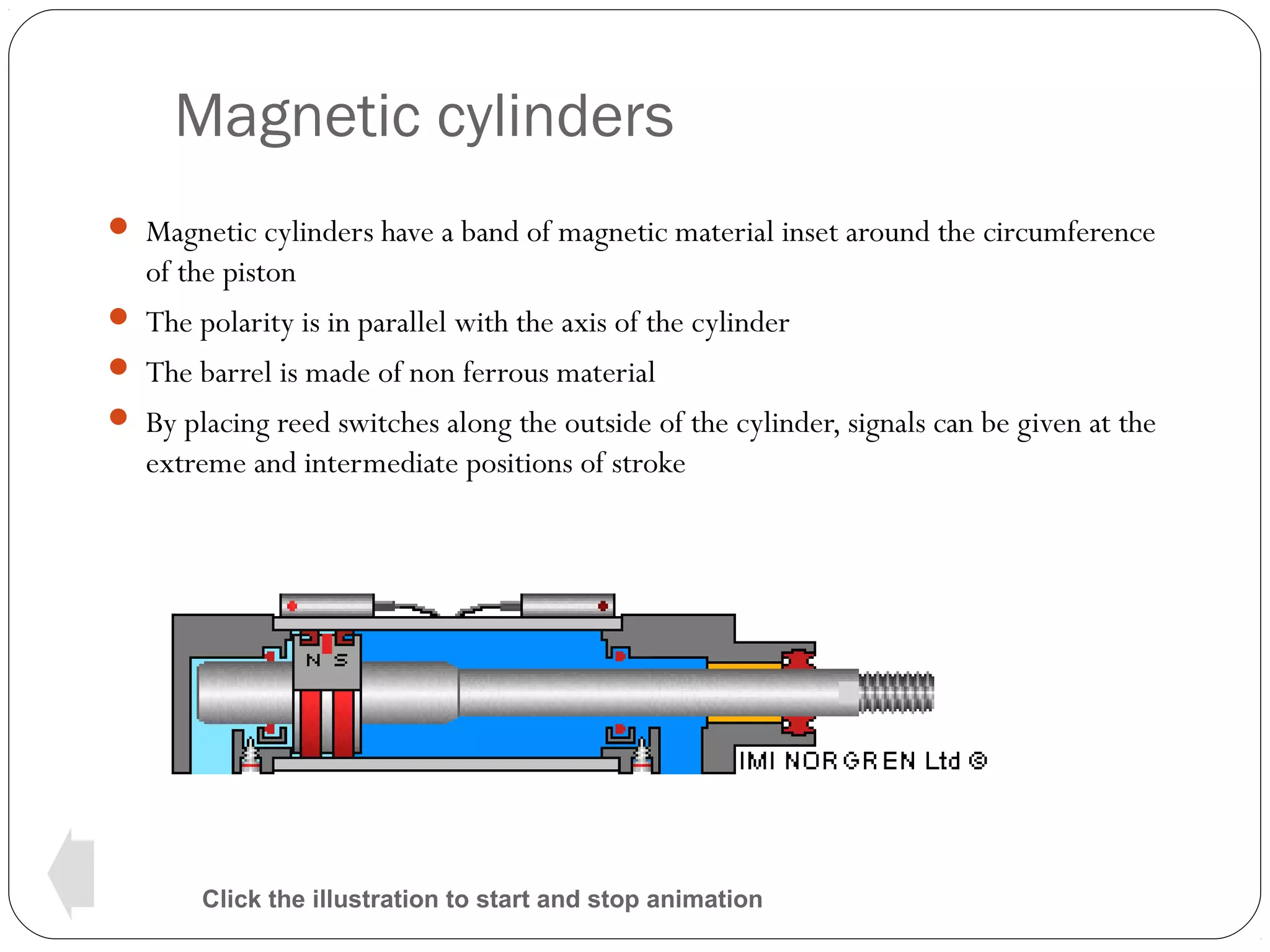
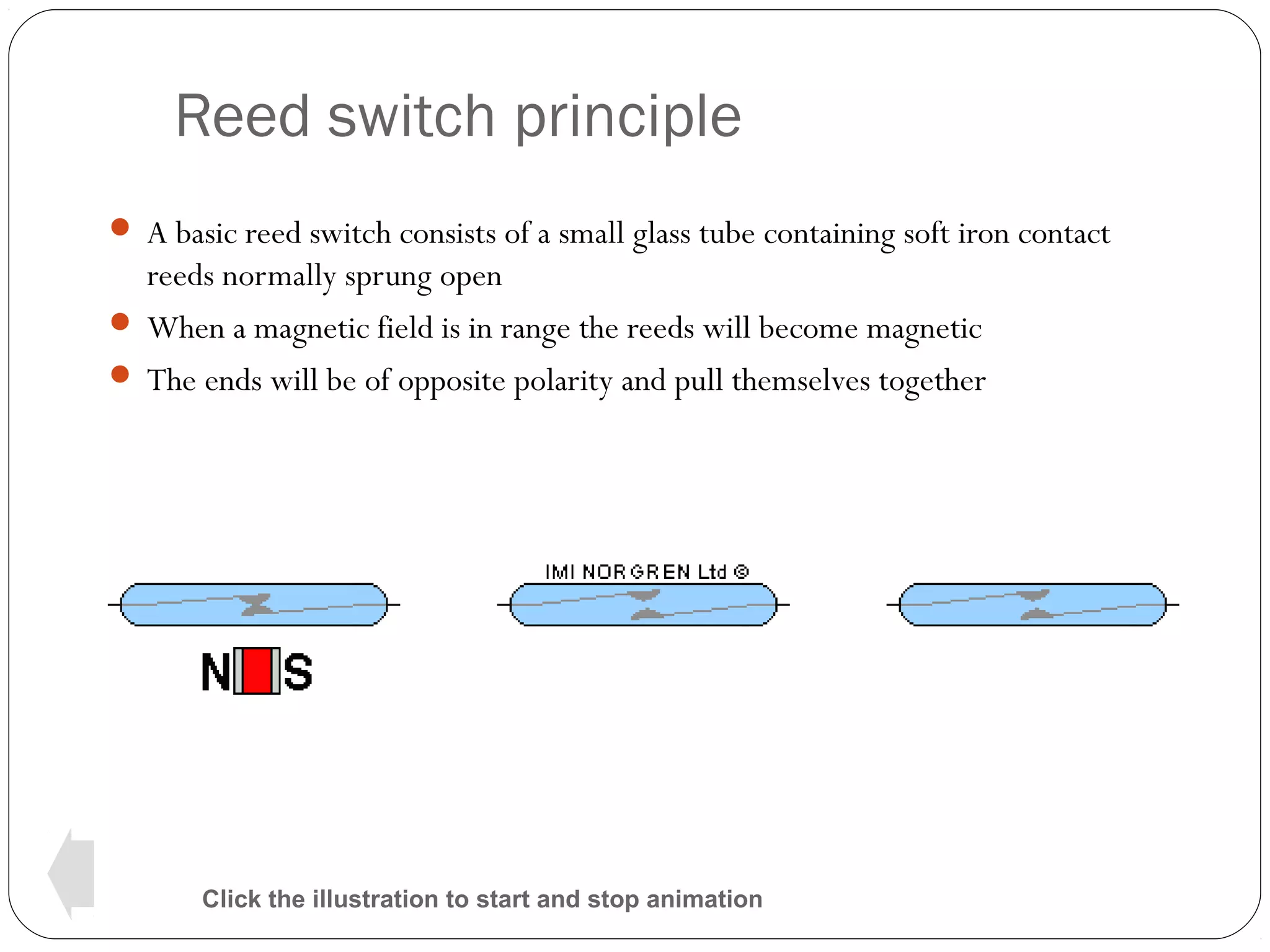
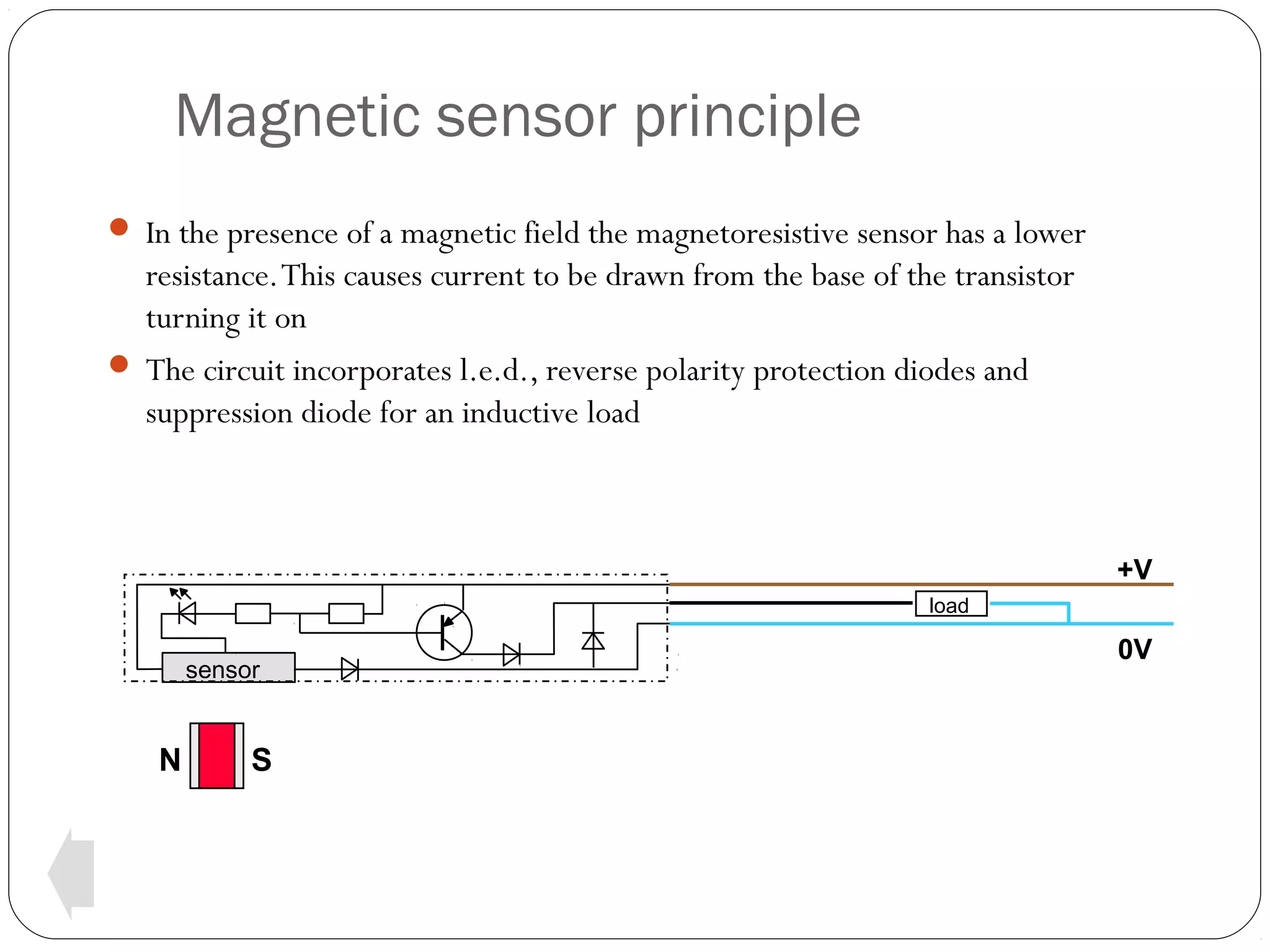
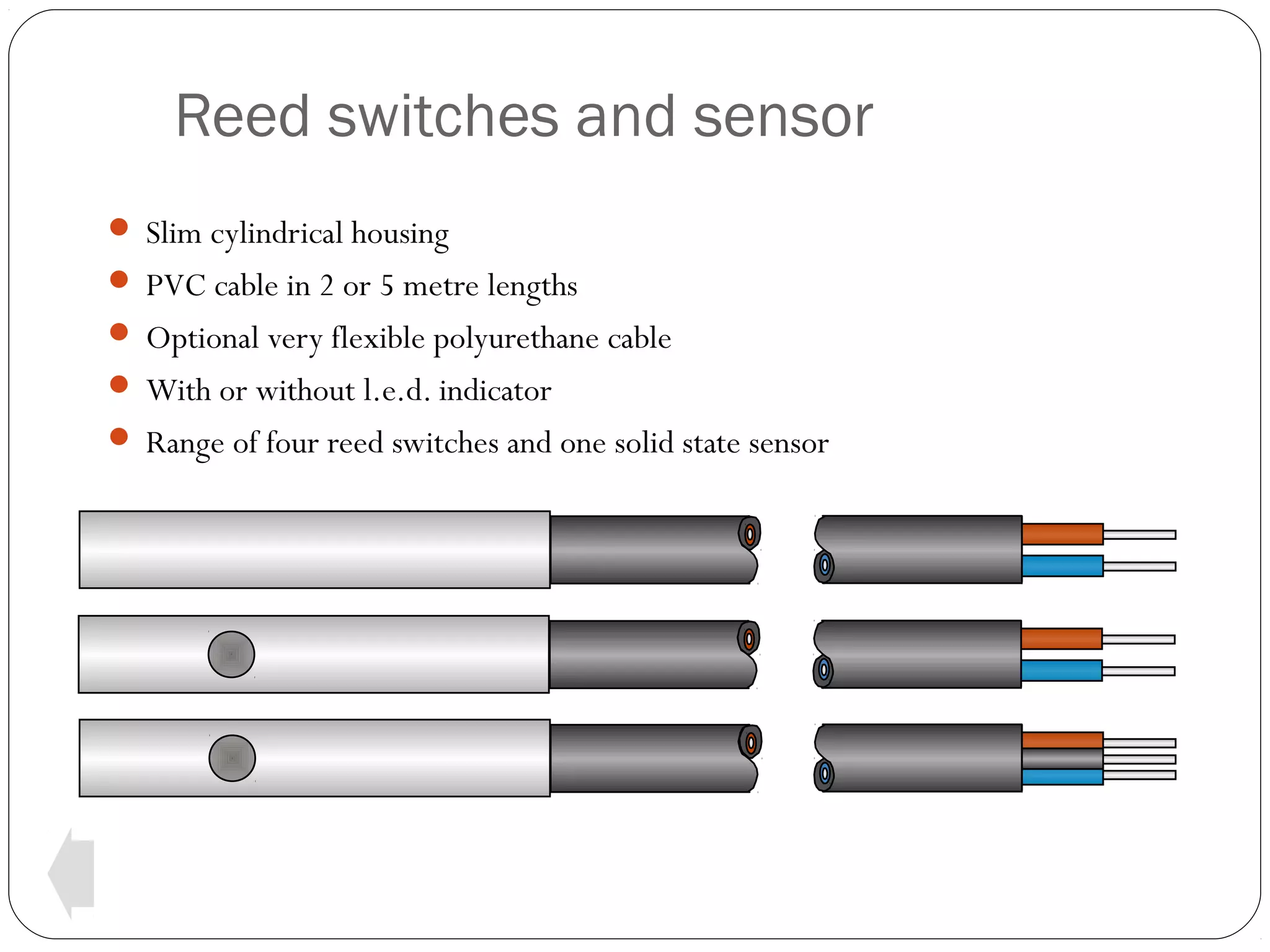
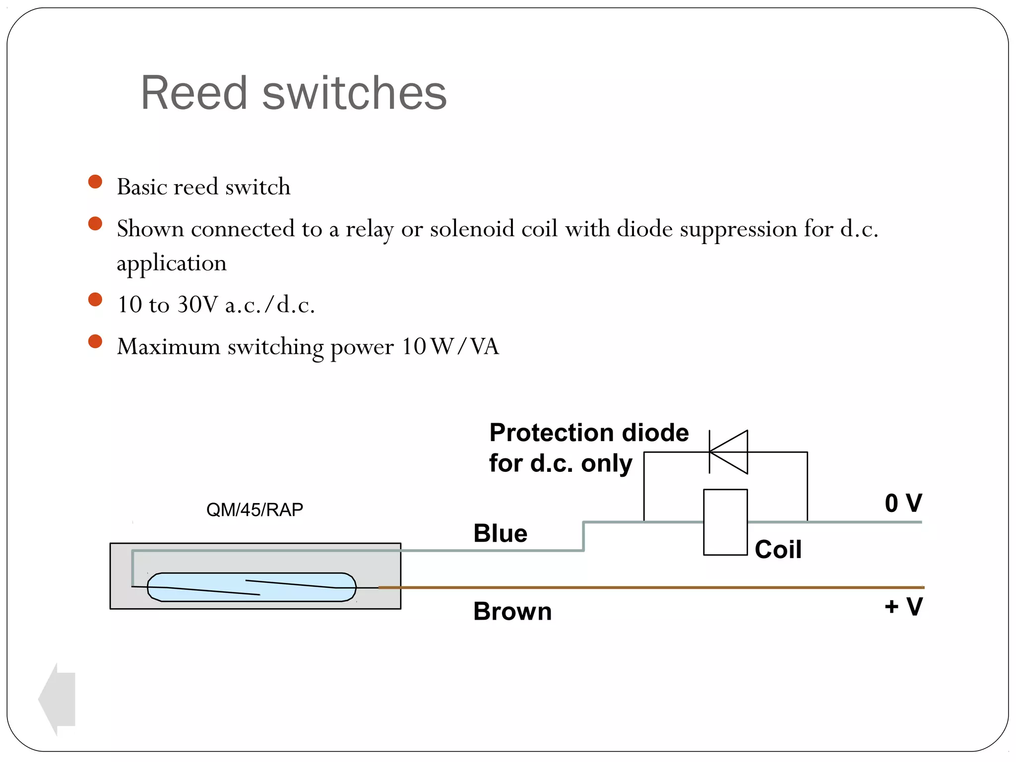
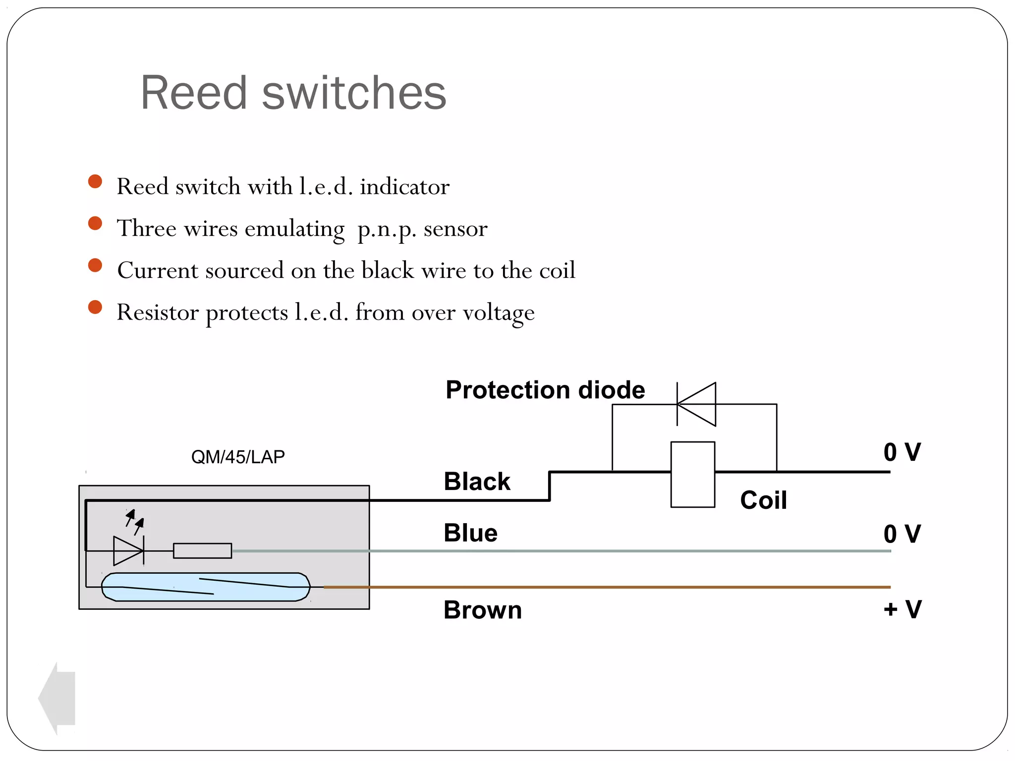
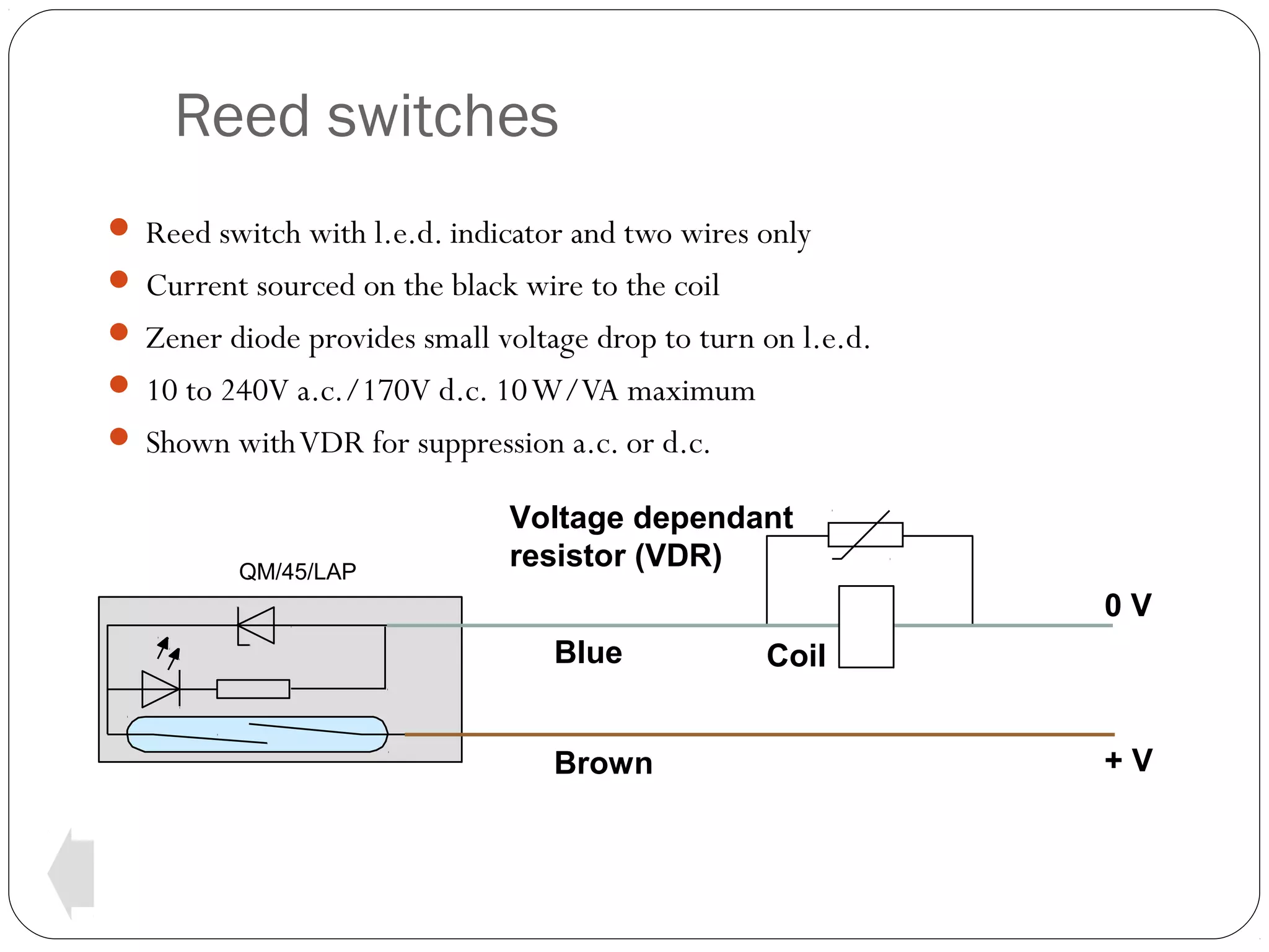
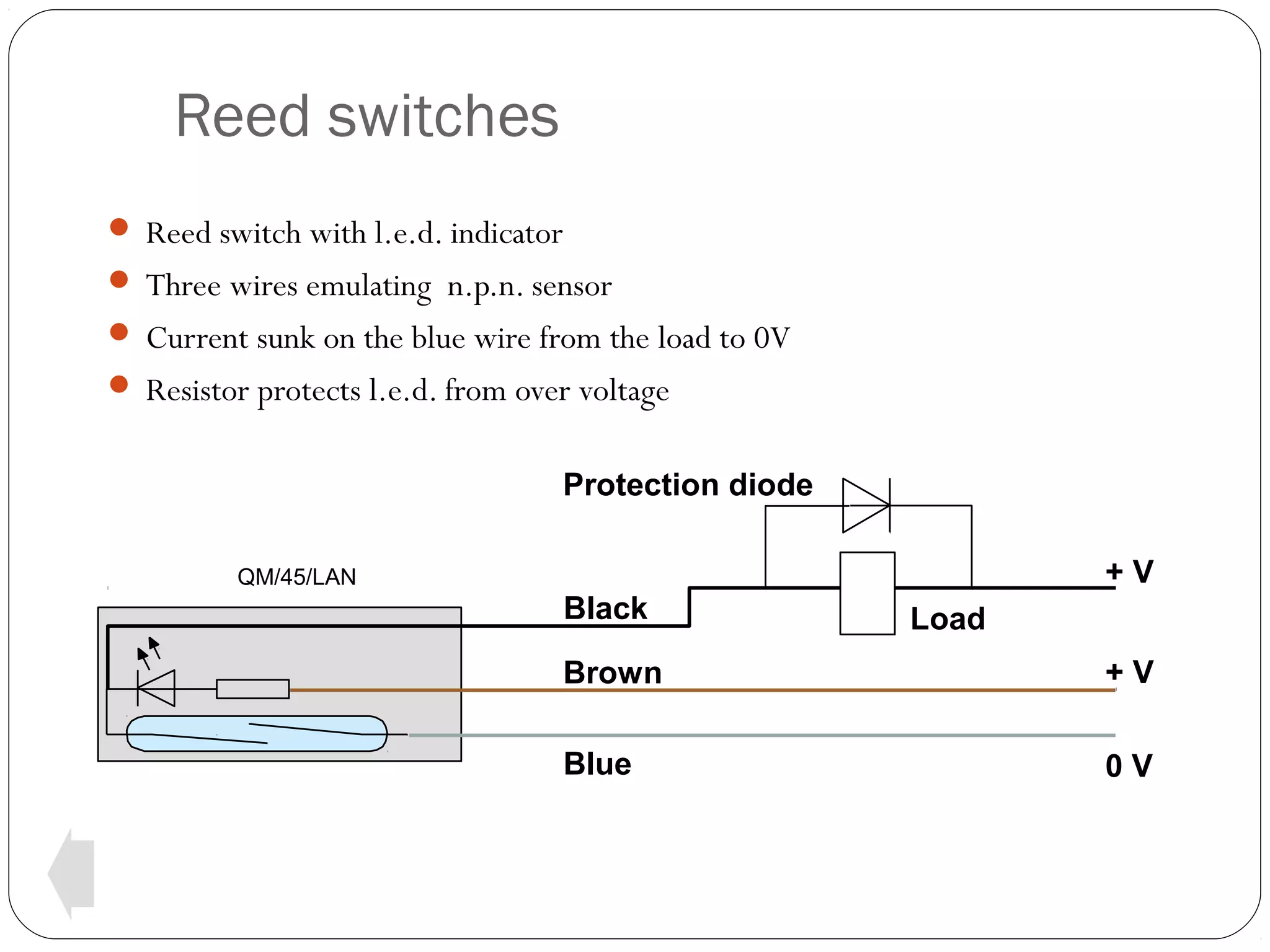
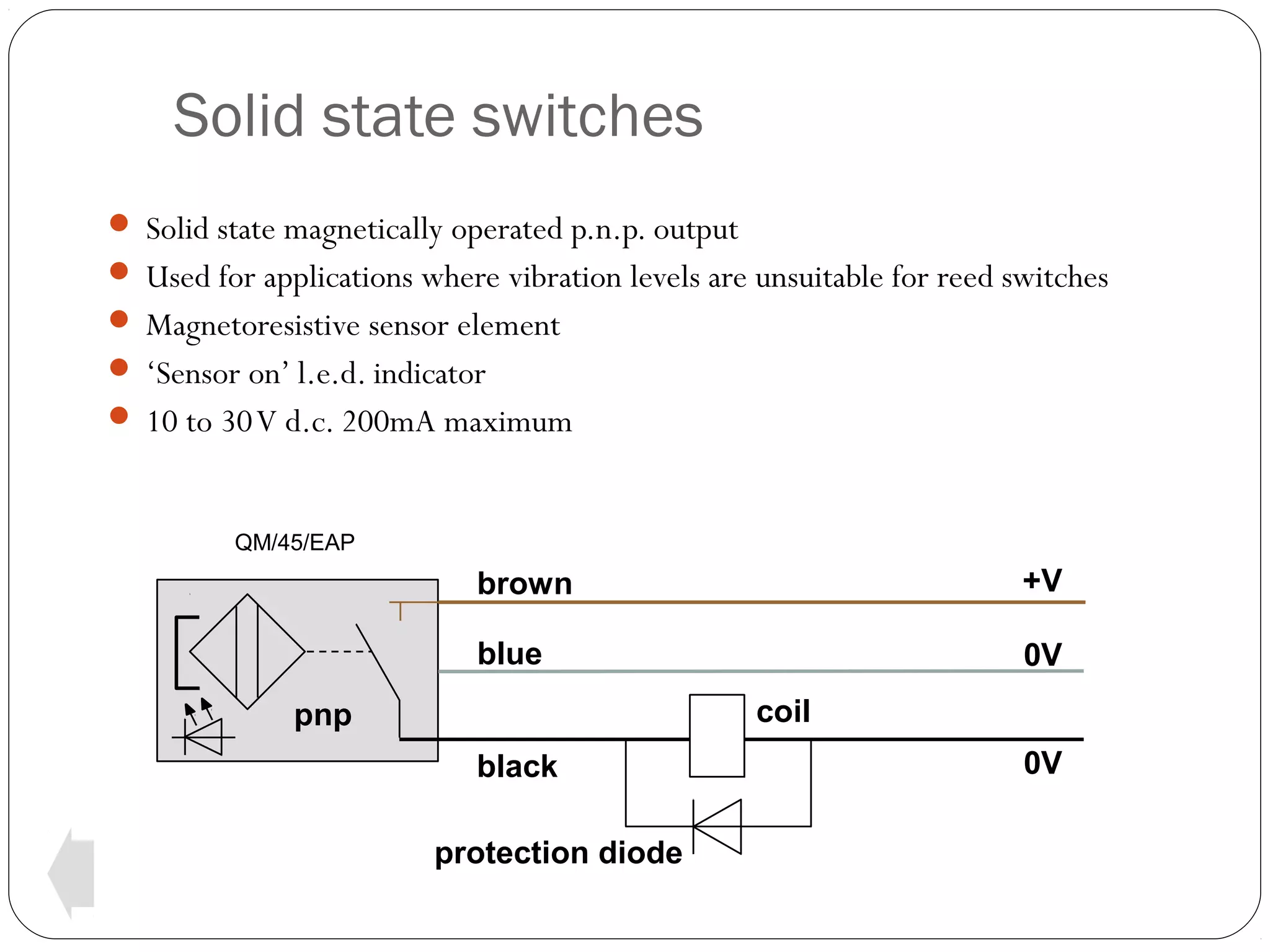
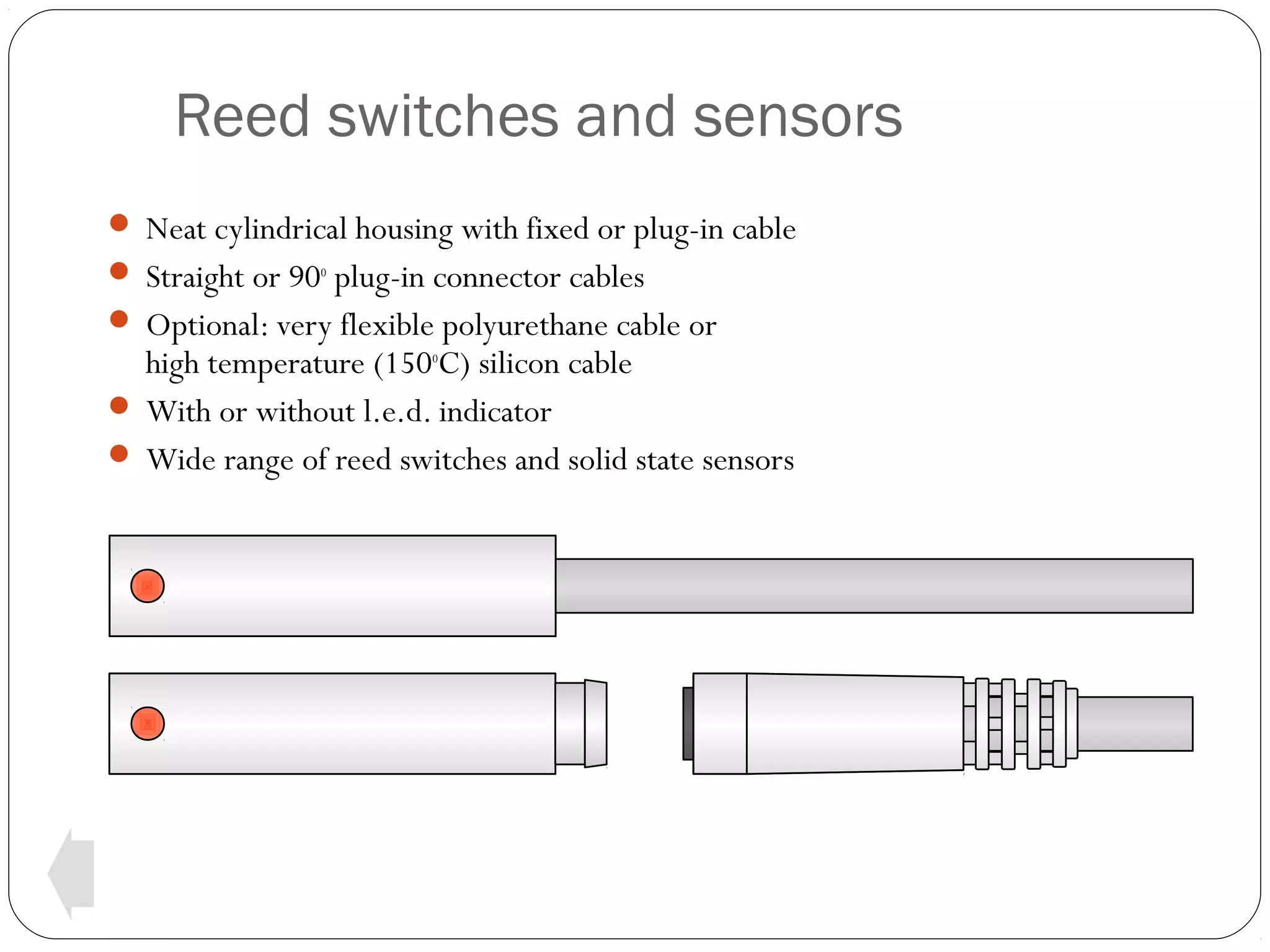
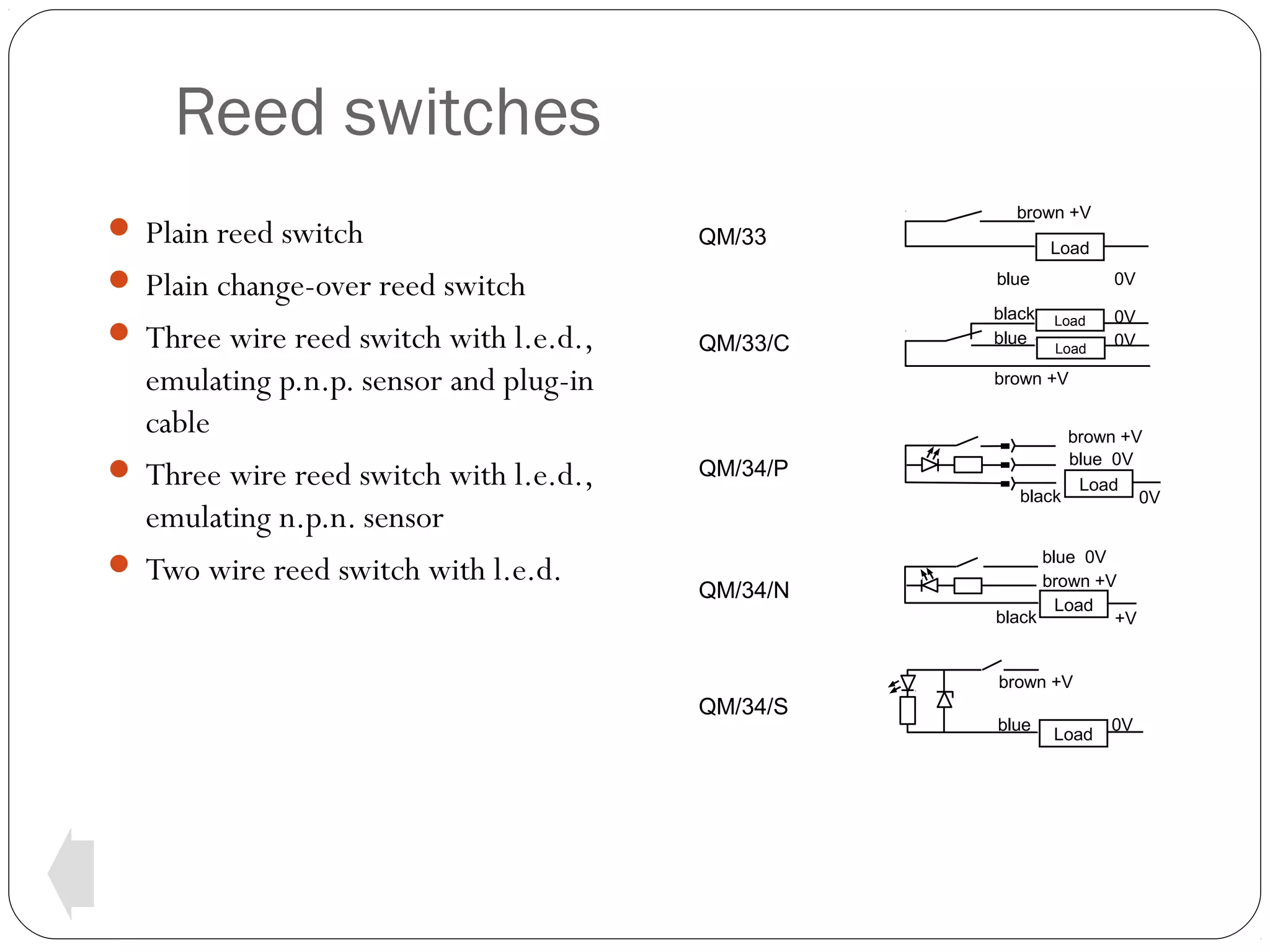
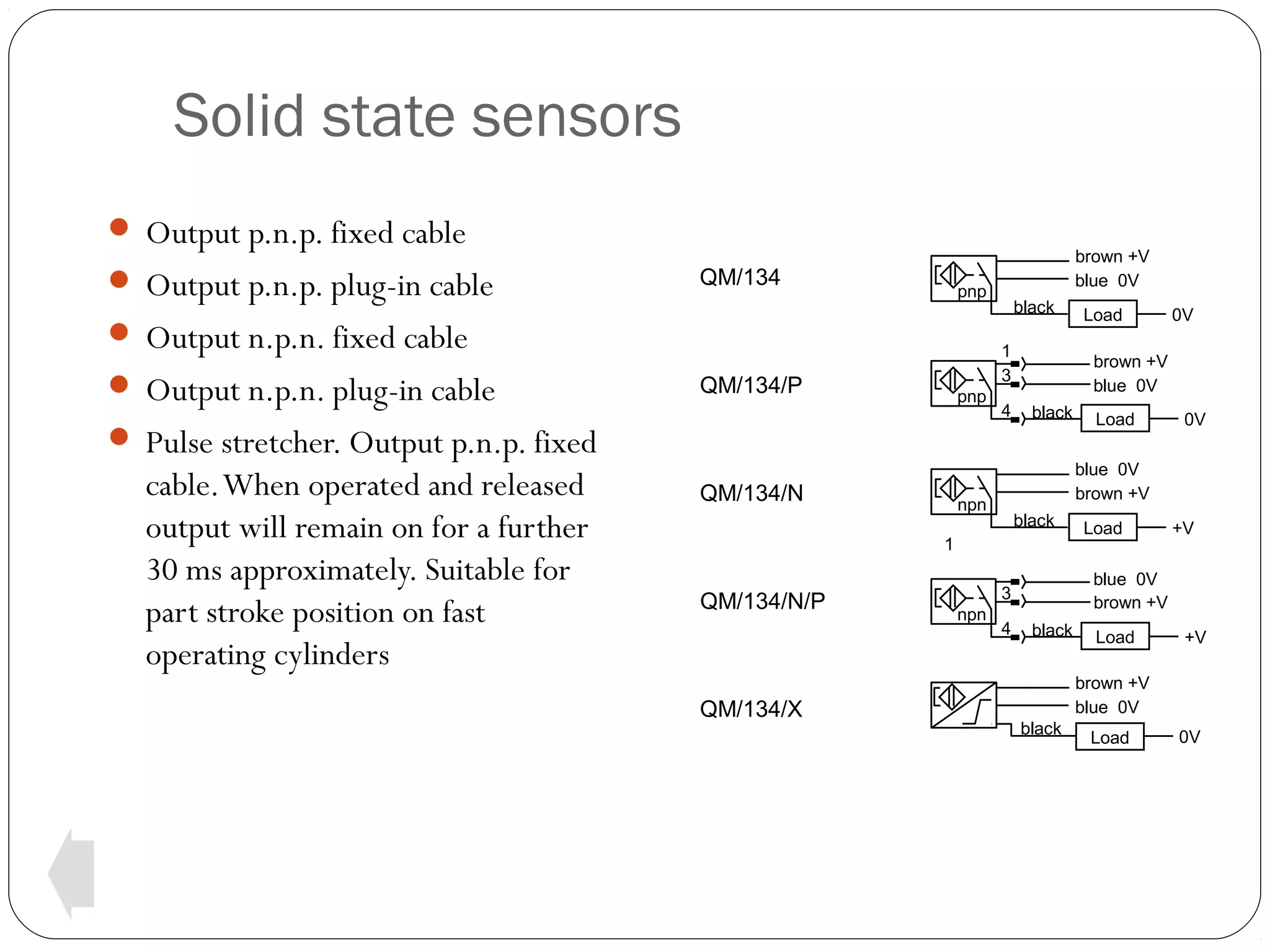
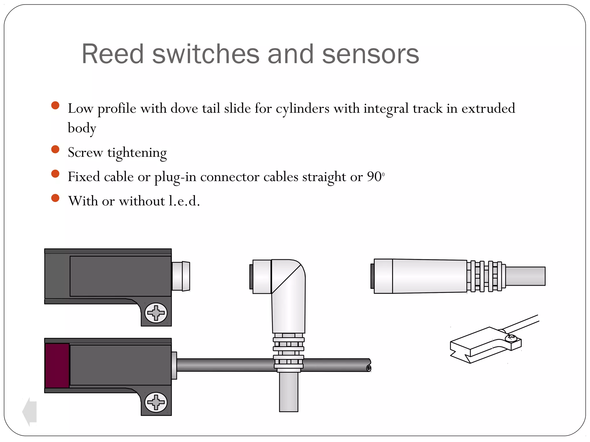
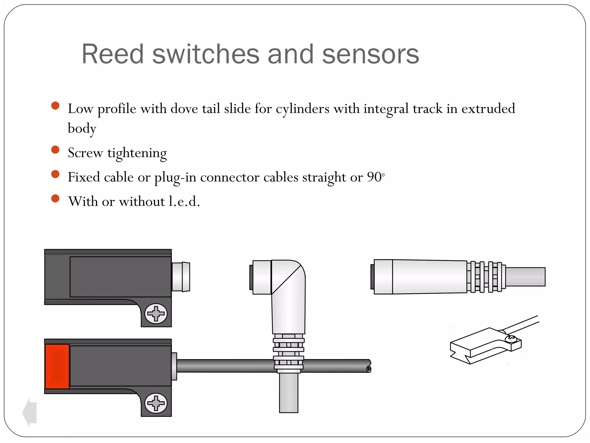
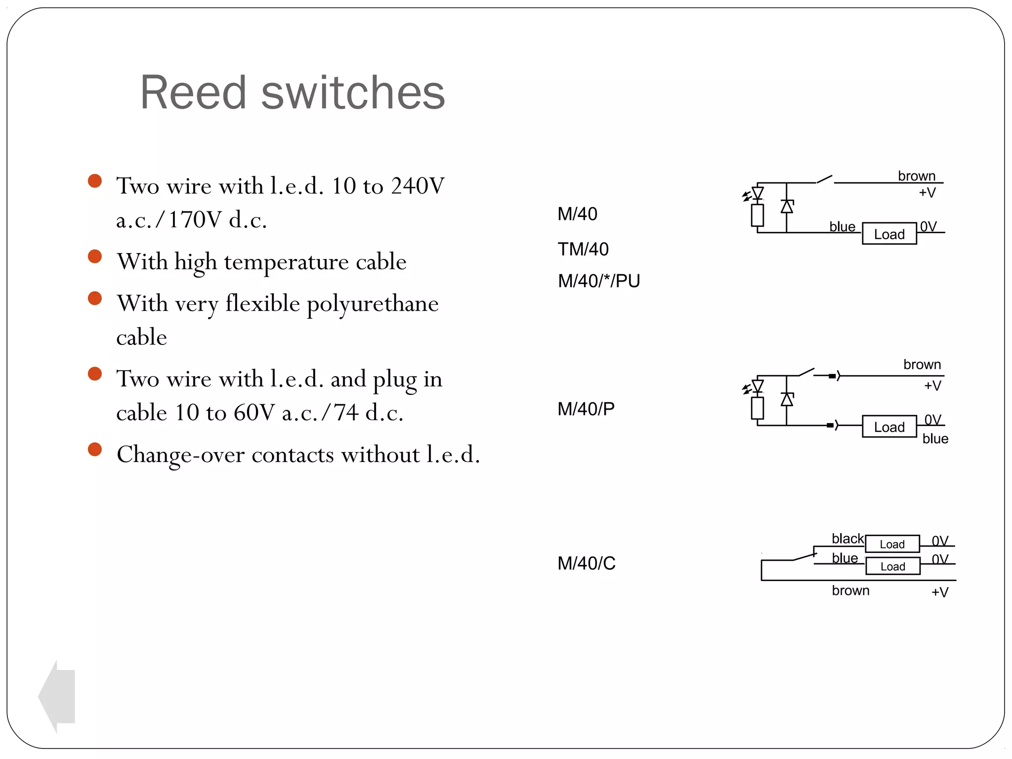
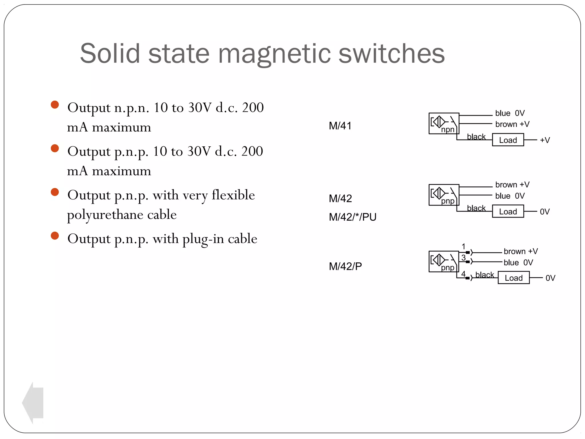
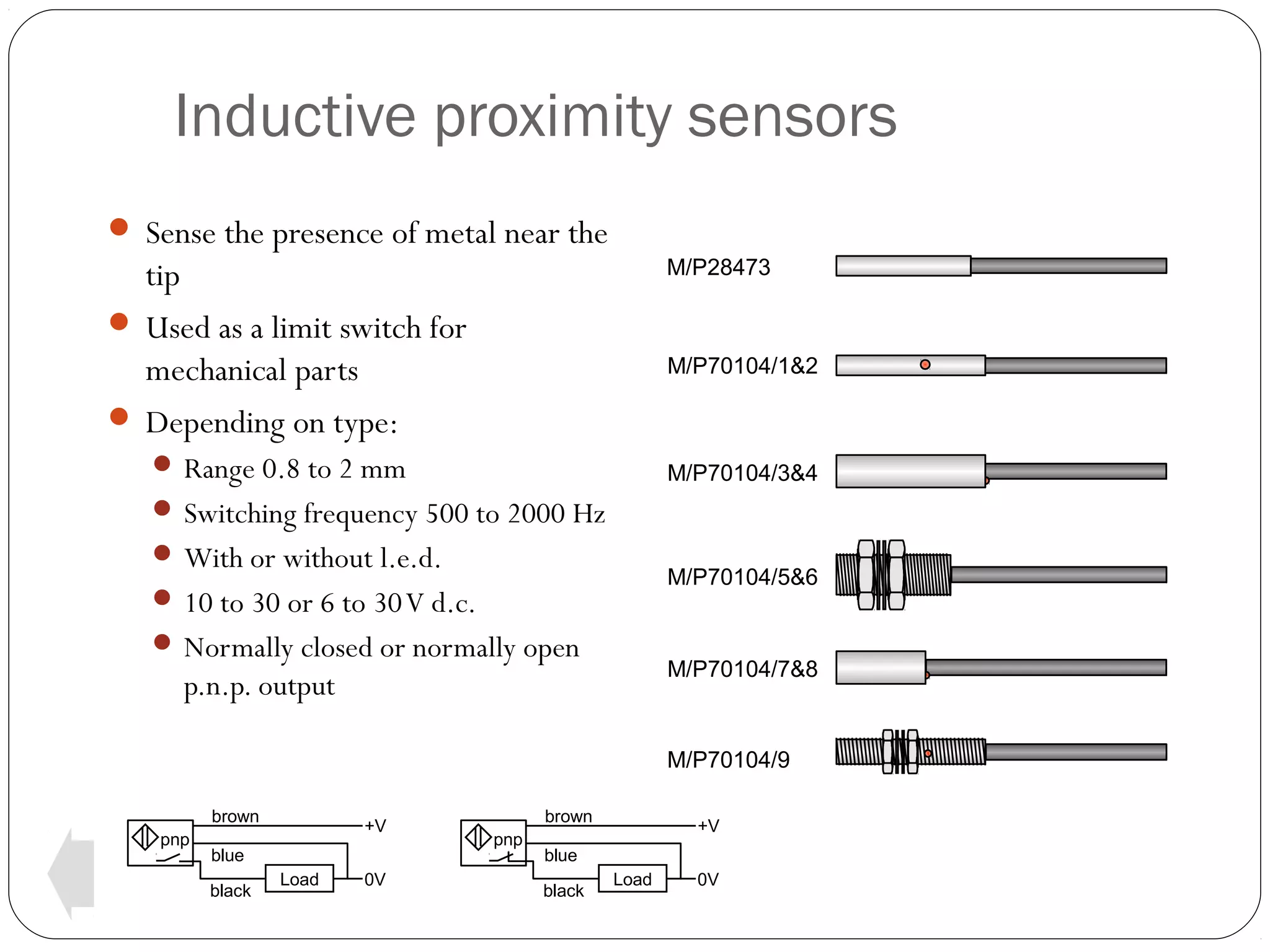


This document discusses various switches and sensors for integrated control systems. It provides details on magnetic cylinders that use reed switches or magnetic sensors to detect piston positions. Reed switches are small, fast, and easy to install. Solid state proximity sensors can replace limit switches. The document describes the operating principles and specifications of reed switches, solid state sensors, inductive proximity sensors, and vacuum electric and solid state switches. It includes diagrams of typical connections and applications.