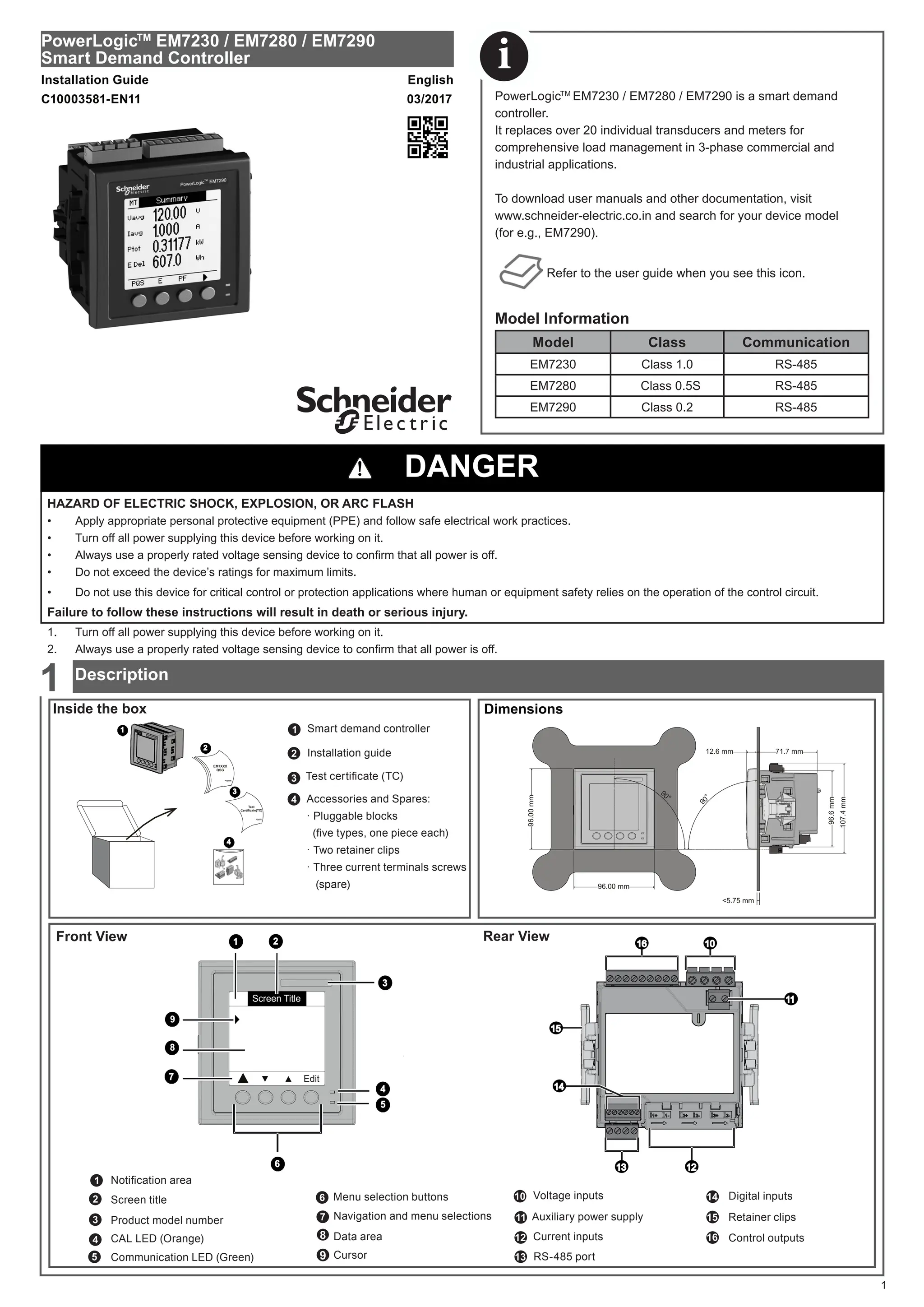
The powerlogictm EM7230/EM7280/EM7290 is a smart demand controller designed for 3-phase commercial and industrial applications, replacing multiple transducers for effective load management. Safety precautions include turning off power during installation to prevent electric shock or equipment damage. Detailed installation, wiring, and configuration instructions are provided for users to ensure correct operation.
![Connector Wire Size Wire Strip Length Torque Screw Driver Type
Auxiliary Power* ,Voltage
Inputs* and Control outputs*
18-12 AWG 0.82-3.31 mm2
0.28 in. 7 mm
4.4-5.3 in-lb 0.5-0.6 N.m
M3 (Flat Screwdriver)
Current Inputs** 18-12 AWG 0.82-3.31 mm2
------- ------- PH 1 (Cross-slotted)
Digital Inputs* 22-14 AWG 0.33-2.08 mm2
0.24 in. 6 mm M2 (Flat Screwdriver)
RS-485 22-12 AWG 0.33-3.31 mm2
0.24 in. 6 mm M3 (Flat Screwdriver)
* Wire ferrules recommended. Wire ferrule determines stripping length
** Current inputs (CTs) must have U or Ring terminal connections
2
92.0 mm
- 0.0
CLICK
CLICK
< 6.4
(< 0.25)
CLACK
CLACK
+ 0.8
92.0
mm
-
0.0
+
0.8
Wire Sizes and Torque
DAMAGE TO THE DEVICE
• Use only the specified tool for tightening and loosening the screw.
• Do not over-torque the screw above the specified range.
• The external peripherals must be interfaced to the appropriate connectors in line with the mentioned specifications.
Failure to follow these instructions can result in equipment damage.
NOTICE
3G'0
!
8/ '0!8/ 5(6725(
CONTROL OUTPUTS (CAT II)
9$ 9
$
9 9 9 91
VOLTAGE INPUT
63.5-277 VLN
110-480 VLL
+]
AUX SUPPLY
9
+]9$
9:
/
1
12
1
12 1 12 1
I I
I I
CURRENT INPUTS
$$120P$$ 9
I I
', ',
DIGITAL INPUTS
90$;
9
Whetting
D0 = Rx- , Tx-
0 V*
D1 = Rx+ , Tx+
Modbus
RS-485
RS-485
' *1'
9
6+/'
'
RS-485
+
-
C
D1 (+)
D0 (-)
+
-
C
120 Ω
Ring-Lug
3.68 ± 0.08
[.14 ± .003]
6.35 / [.250] MAX
3.68 ± 0.08 DIA
[.145 ± .003]
6.35 / [.250] MAX
Note : * Connect both the wires from the second twisted pair on the terminating end to ensure all wires are connected.
U-Lug
DANGER
HAZARD OF ELECTRIC SHOCK, EXPLOSION, OR ARC FLASH
• Do not use this device for critical control or protection applications where human or equipment safety relies on the operation of the control circuit.
• Do not open the demand controller.
• Use appropriate fuse for the control outputs.
Failure to follow these instructions will result in death or serious injury.
Mounting
2
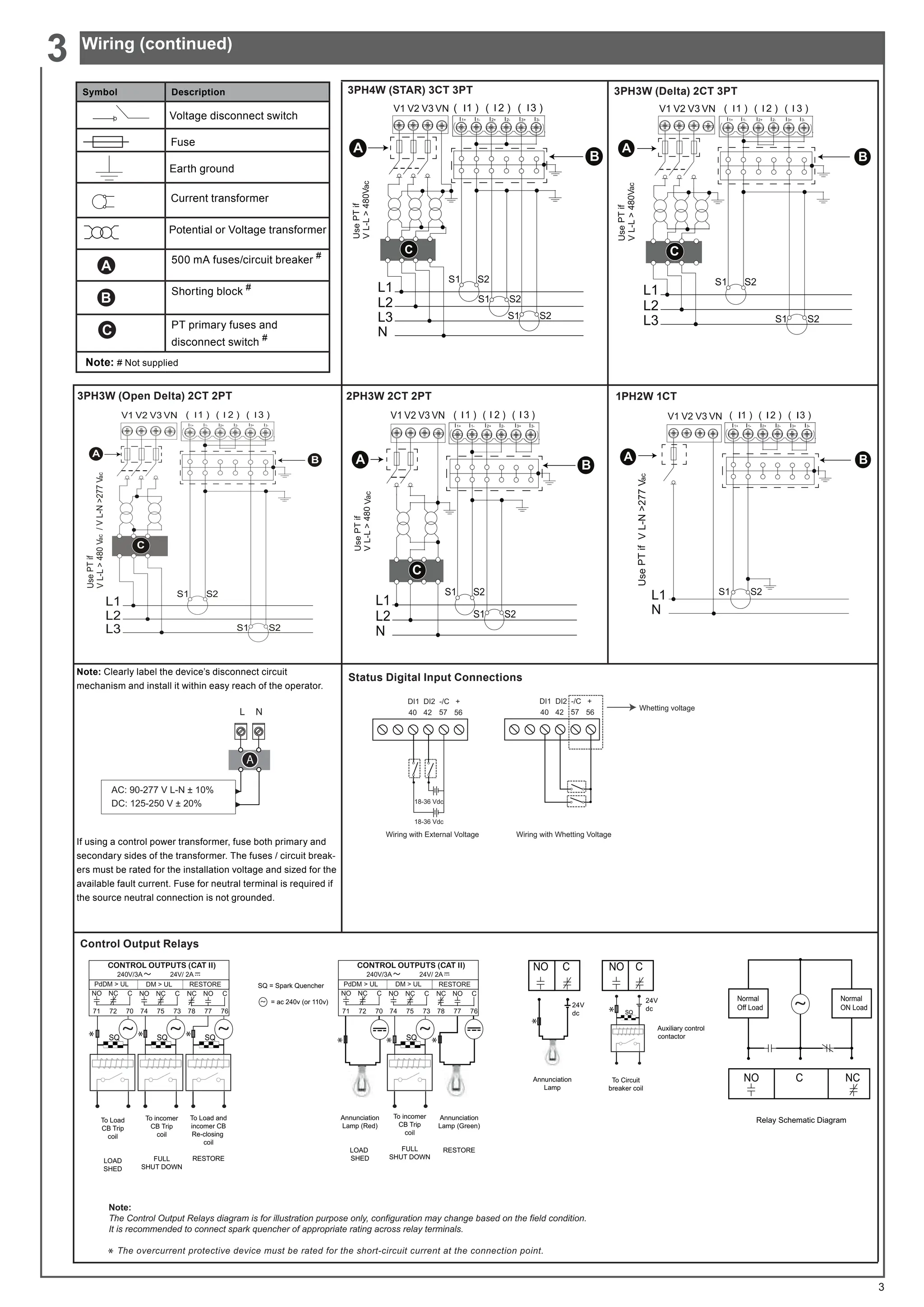
Wiring
3](https://image.slidesharecdn.com/digital-demand-controllers-240706055516-da9d8d94/75/Energy-management-demand-controllers-pdf-2-2048.jpg)
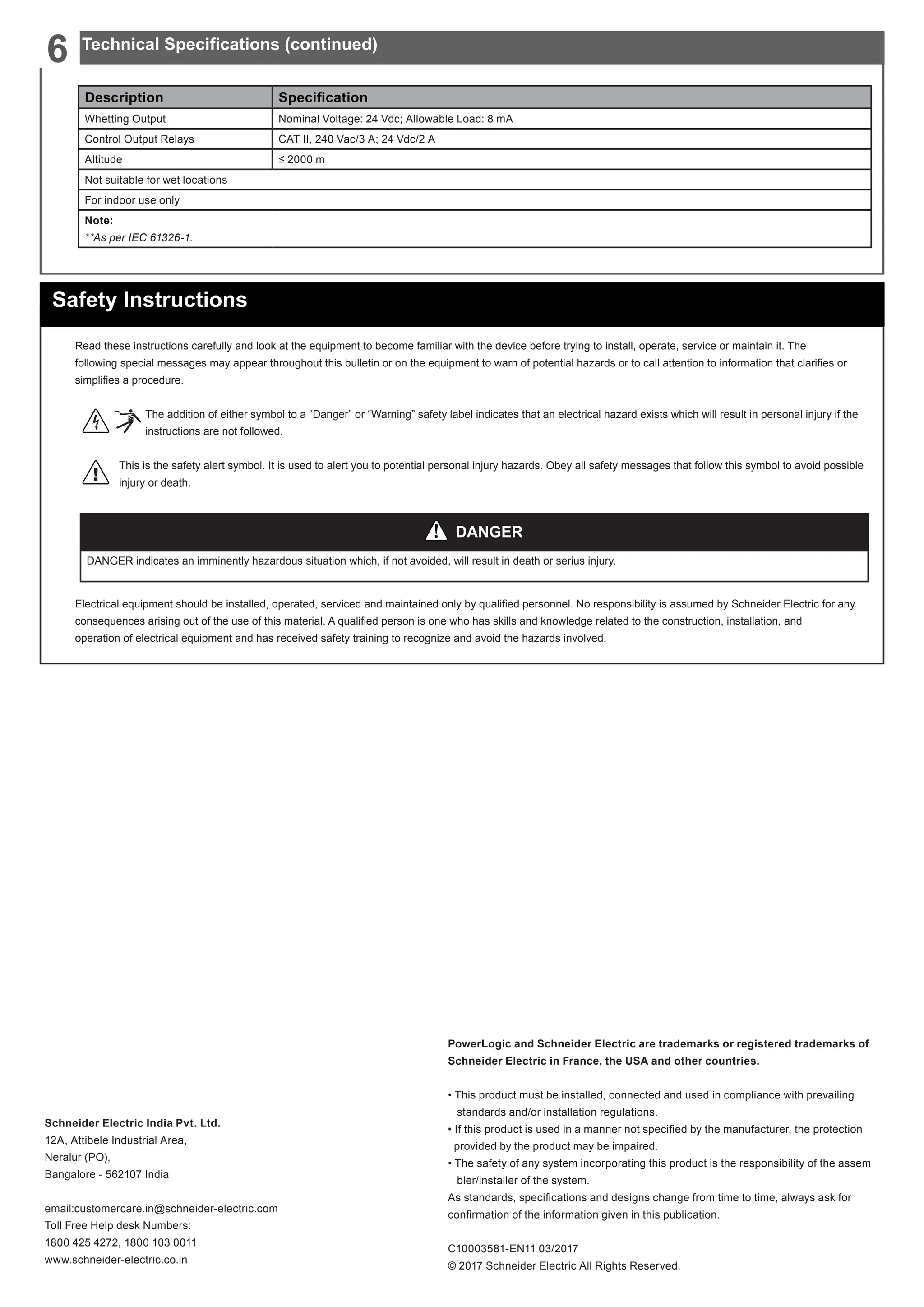
![Description Specification
Sensing/Measurement True RMS, one second update time, four quadrant power and energy
Accuracy
PARAMETER EM7230 EM7280 EM7290
Active Energy
Class 1.0
as per IEC 62052-11 and
IEC 62053-21
Class 0.5S
as per IEC 62052-11 and
IEC 62053-22 (1)
Class 0.2
as per IEC 62052-11 and
IEC 62053-22 (1)(2)
Reactive Energy
Class 2.0
as per IEC 62052-11 and
IEC 62053-23
Class 2.0
as per IEC 62052-11 and
IEC 62053-23
Class 2.0
as per IEC 62052-11 and
IEC 62053-23
Active Power ± 1.0 % ± 0.5 % ± 0.2 %
Reactive Power ± 2.0 % ± 2.0 % ± 2.0 %
Apparent Power ± 1.0 % ± 0.5 % ± 0.2 %
Current and Voltage ± 1.0 % ± 0.5 % ± 0.5 %
Frequency ± 0.1 %
(1)
For 1A nominal CT, accuracy is applicable with an additional error of ± 1 % from 50 mA to 150 mA and ± 3 % from 10 mA to 50 mA.
(2)
Class 0.2S accuracy is applicable in 3P4W configuration with 5A CT nominal at 50Hz, tested in accordance with the test methods and
error limits given as per IEC 62052-11 and IEC 62053-22.
Auxiliary supply (control power)
AC: 90-277 V L-N ±10%
DC: 125-250 V ± 20%
Burden
Voltage and current input 0.2 VA per phase
Auxiliary supply (control power): Max 10 VA at 240 Vac; Max 4.5 W at 300 Vdc
Display
Monochrome Graphics LCD
Display: every 1 second
Demand update: every 15 seconds
Harmonic (%) update: every 5 seconds
Resolution 128x128 pixels
Input Voltage
Voltage inputs (V1, V2, V3, VN)
110/480 Vac LL nominal (range : 63.5-277 Vac LN ; 110-480 Vac LL)
Input current (energy measurement)
Current inputs (I1, I2, I3);
5A Nominal current: 50 mA to 6 A (Starting current: 5 mA)
1A Nominal current: 10 mA to 1.2 A (Starting current: 5 mA)
Frequency 50 / 60 Hz ± 5%
Overload 10 A max continuous, 50 A @ 10 sec/hr, 500 A @ 1sec/hr
Environmental
Operating temp: −10 °C to 60 °C (14 °F to 140 °F)
Storage temp: −25 °C to 70 °C (−13 °F to 158 °F)
Humidity 5 % to 95 % non-condensing
Safety
Measurement category: CAT III
Pollution Degree 2
Double insulation at user-accessible area
Communication
RS-485 serial channel connection.
Industry standard Modbus RTU protocol.
Baud rate support: Minimum: 4800; Maximum: 38400; Default: 19200
IP Degree of Protection
Front display: IP 51
Meter body: IP 30 (except connectors)
Product Weight 380 g (approx.)
Dimensions W x H x D [protrusion
from cabinet]
96 x 96 x 71.7 mm (depth of meter from housing mounting flange) [12.6 mm]
Standards and Certifications
Certifications:
as per IEC/UL 61010-1 Edition-3
Standards:
Emission: CISPR11 Class A; Fast Transient: IEC 61000-4-4**
Surge withstand: IEC 61000-4-5**
ESD: IEC 61000-4- 2**
Radiated Susceptibility: IEC61000-4-3**
Conducted susceptibility: IEC61000-4-6**
Voltage dips and interruptions: IEC61000-4-11**
Status Digital Inputs
Voltage Ratings: ON 18.5 to 36 Vdc ; OFF 0 to 4 Vdc
Input Resistance: 110 k Ohms
Maximum Frequency: 2 Hz, 50% duty cycle
Response Time: 10 milliseconds
7
4ZW2
Technical Specifications
6](https://image.slidesharecdn.com/digital-demand-controllers-240706055516-da9d8d94/75/Energy-management-demand-controllers-pdf-7-2048.jpg)