Downloaded 906 times
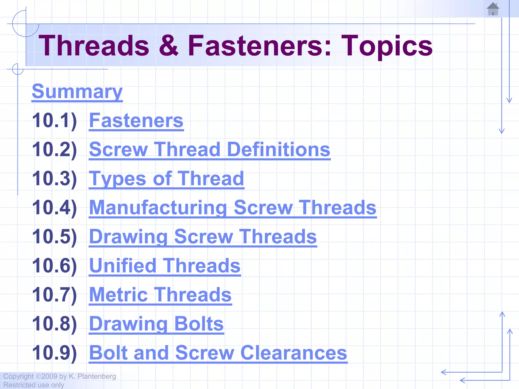

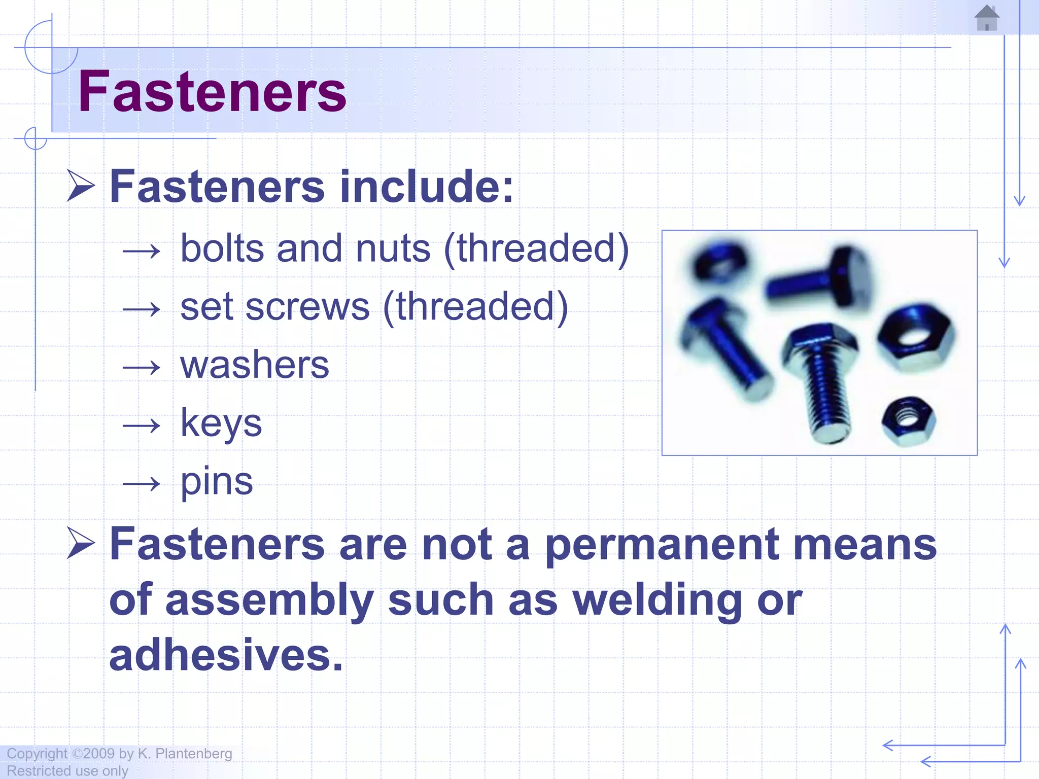

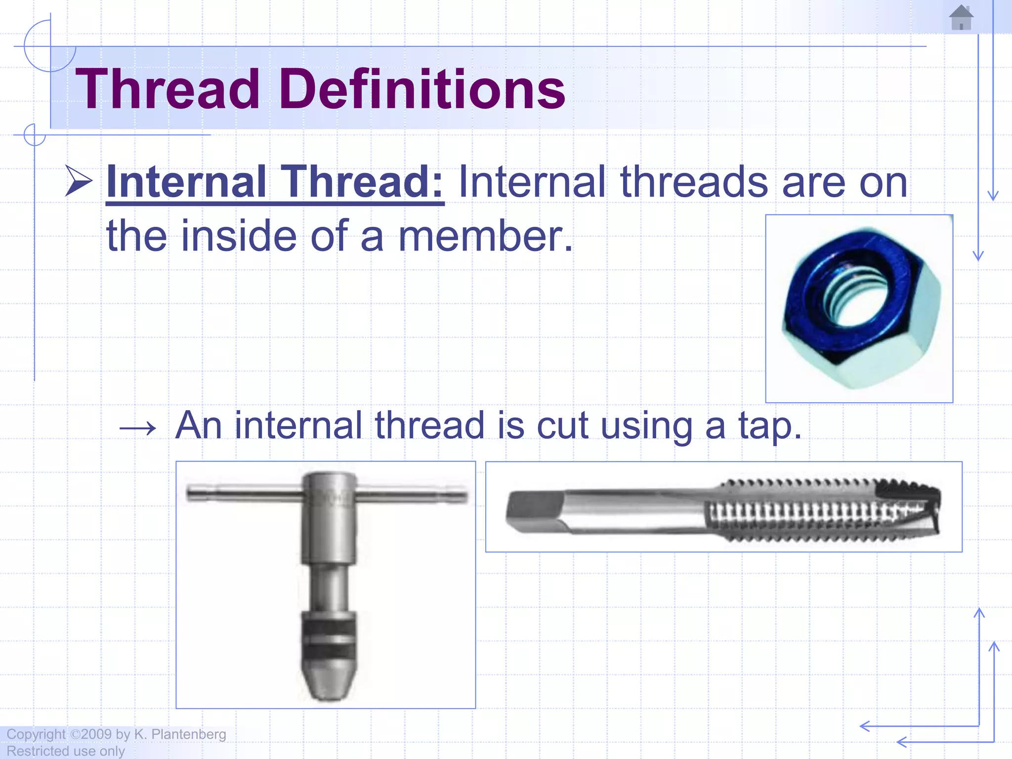
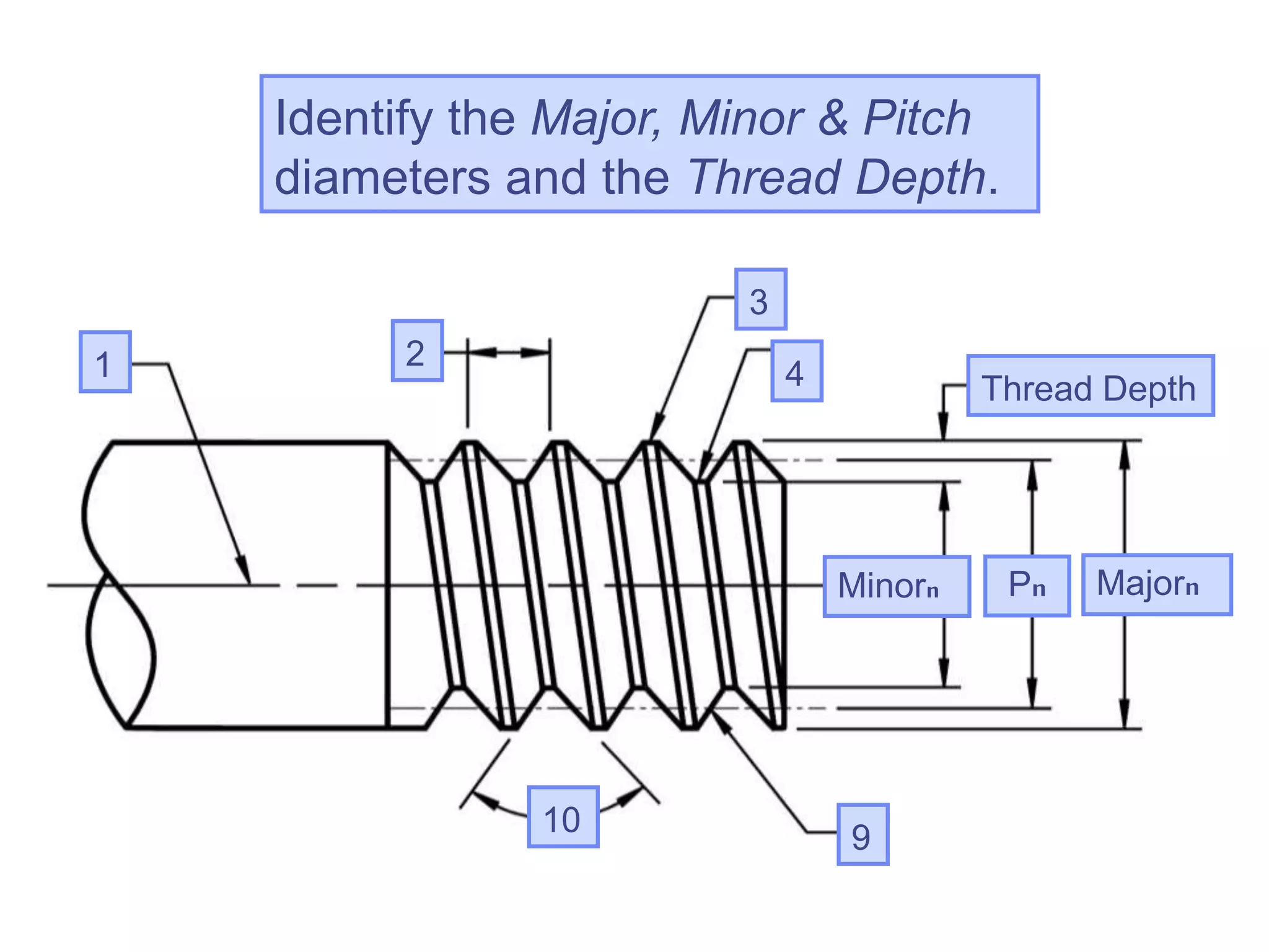
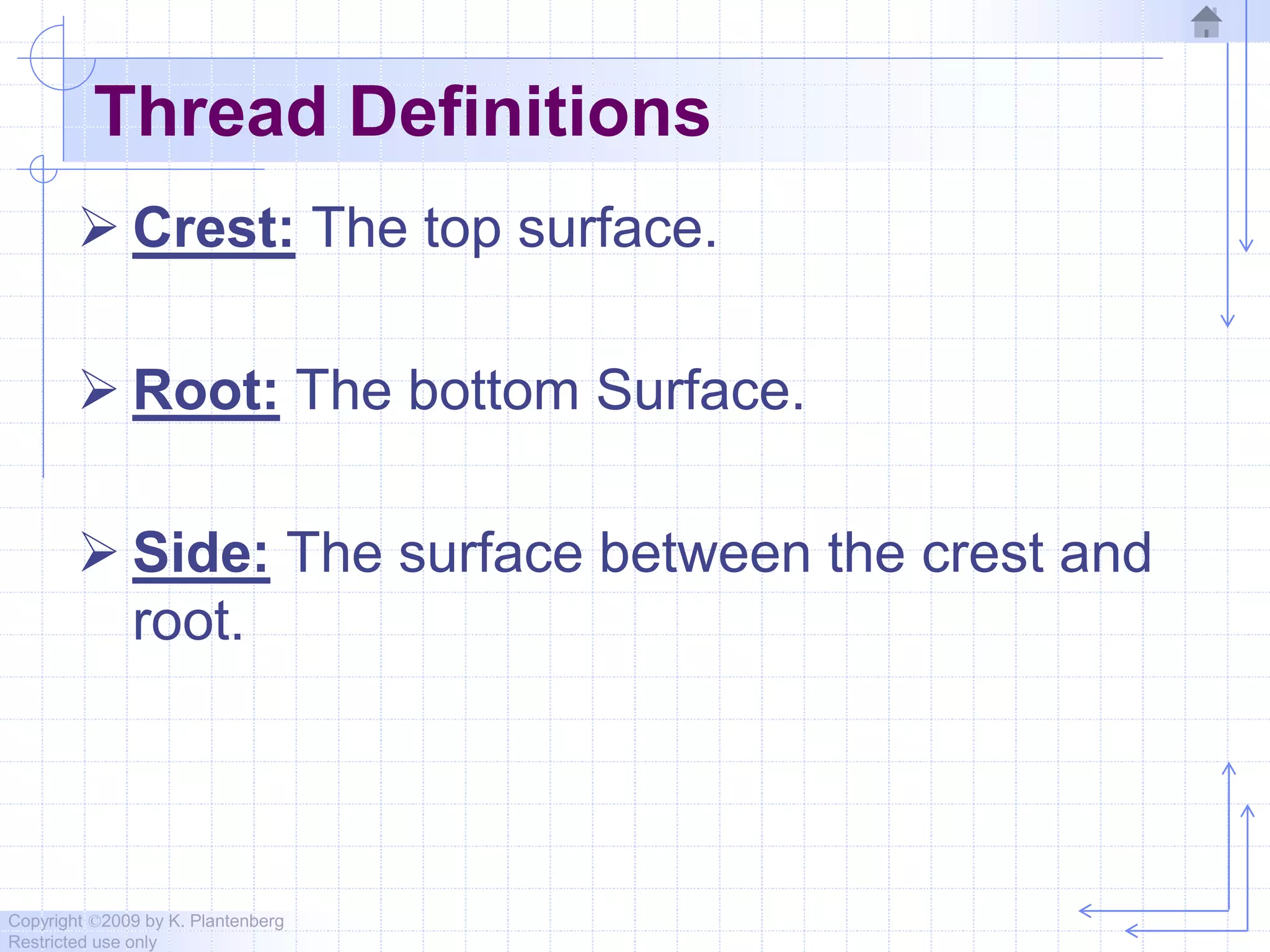
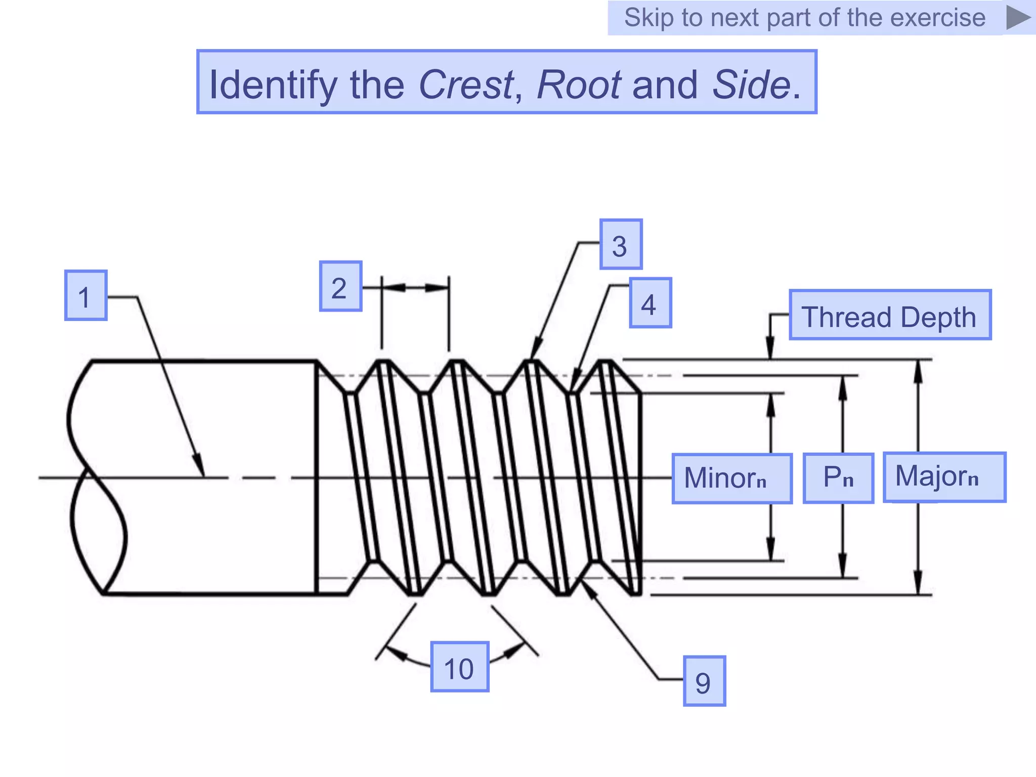
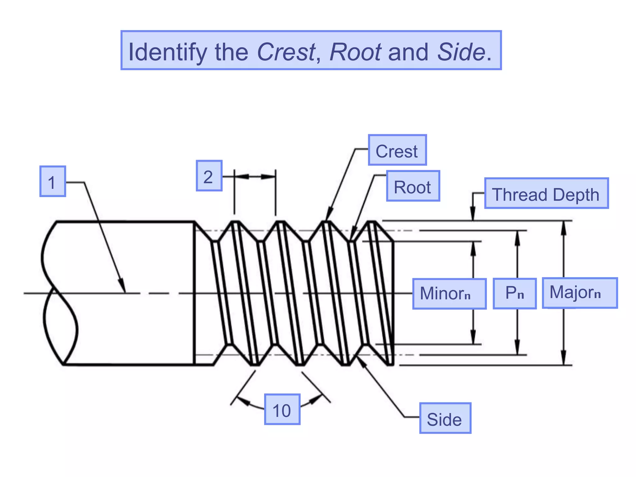

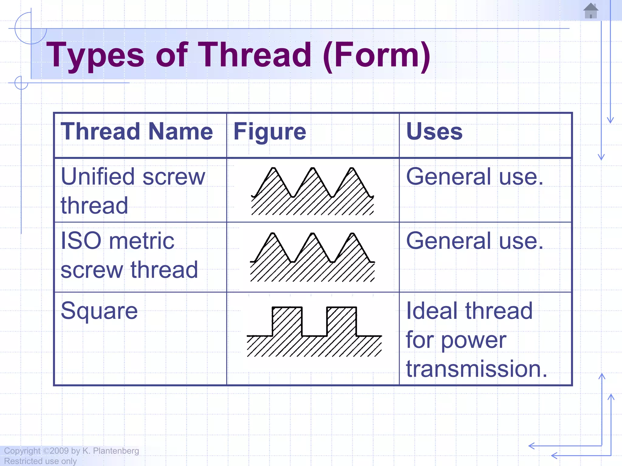
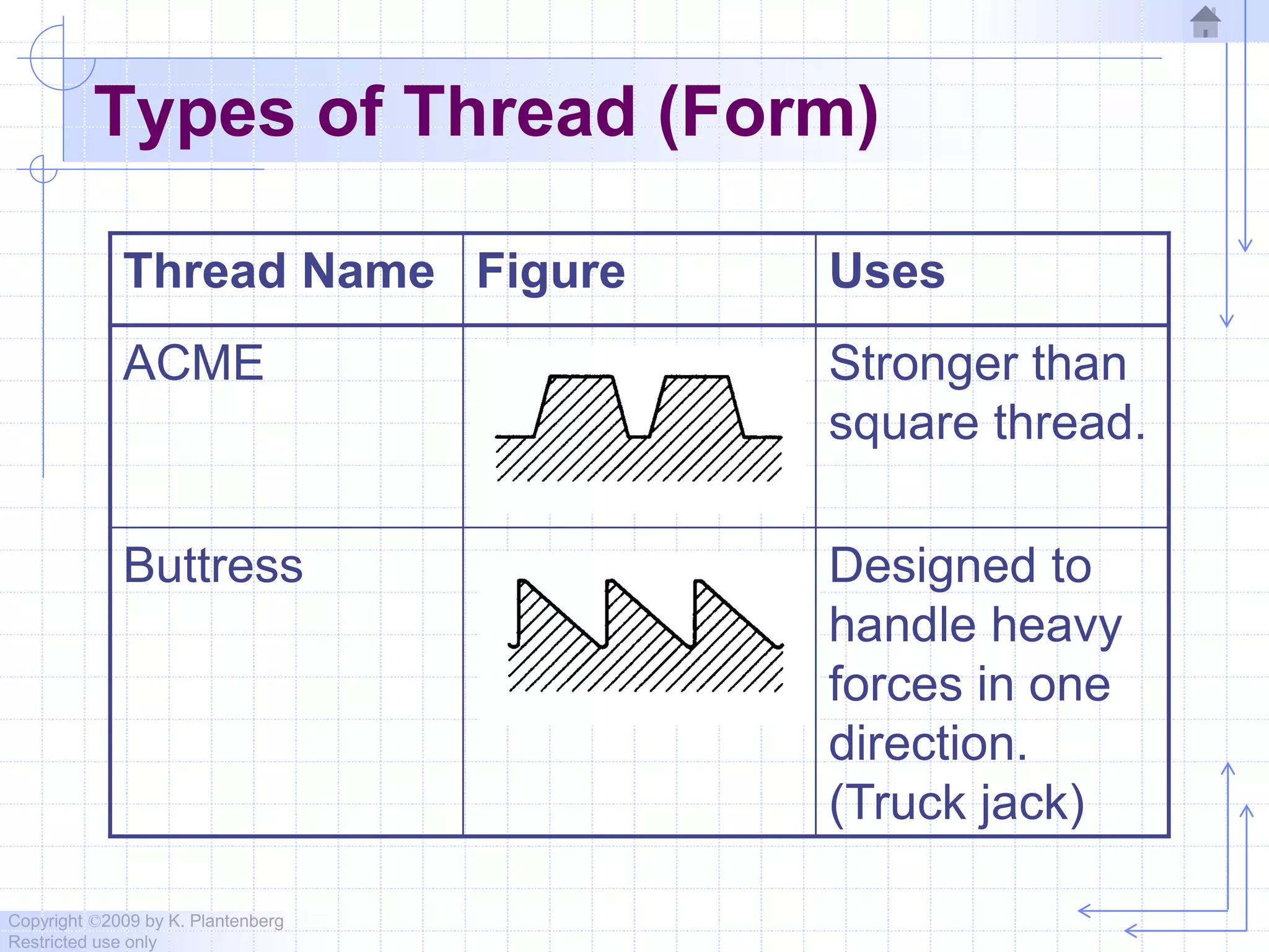
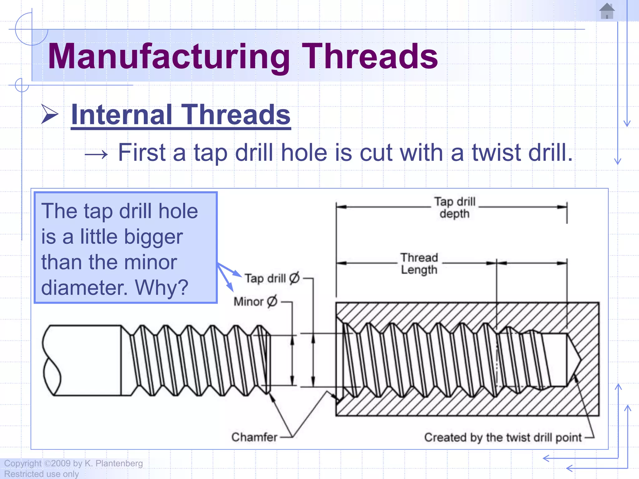
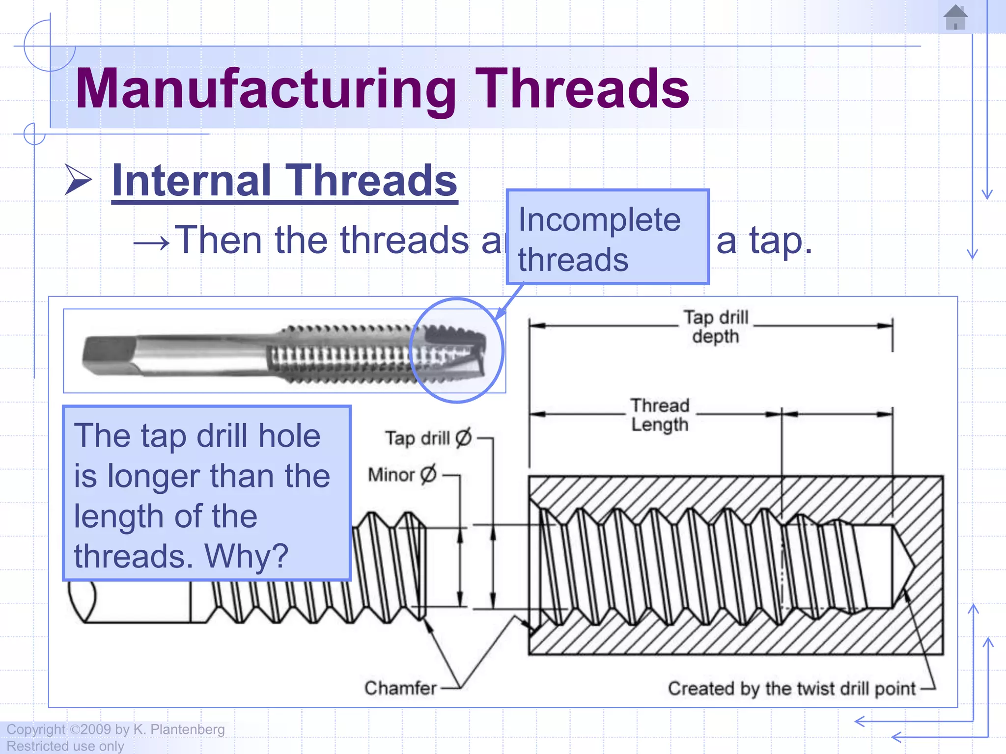
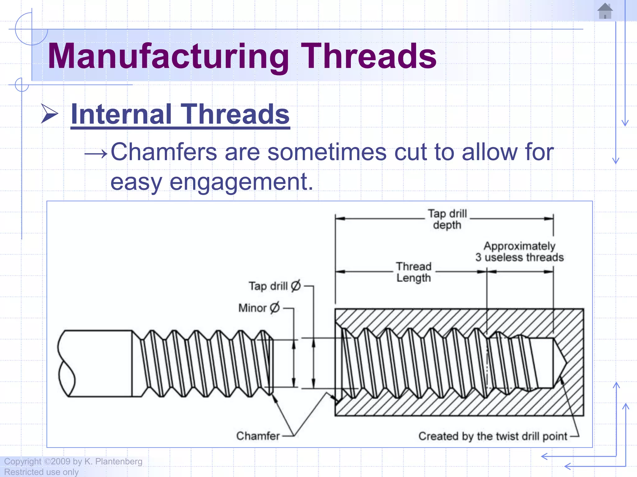
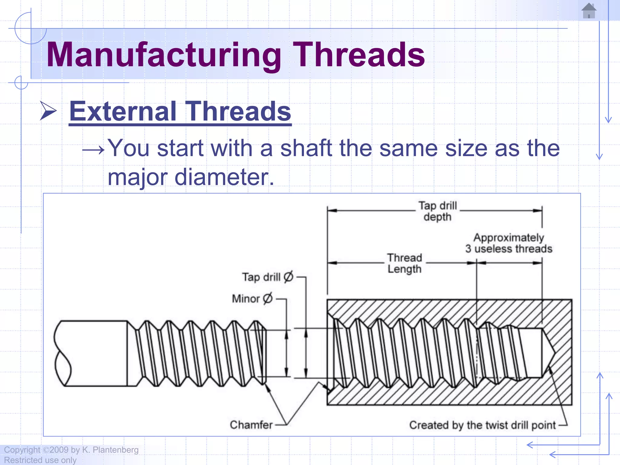
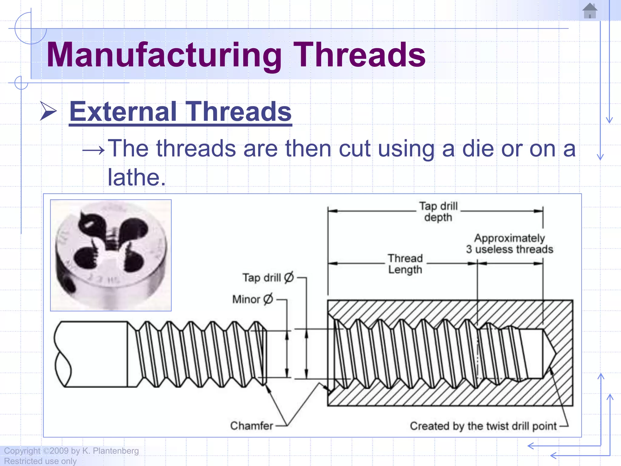
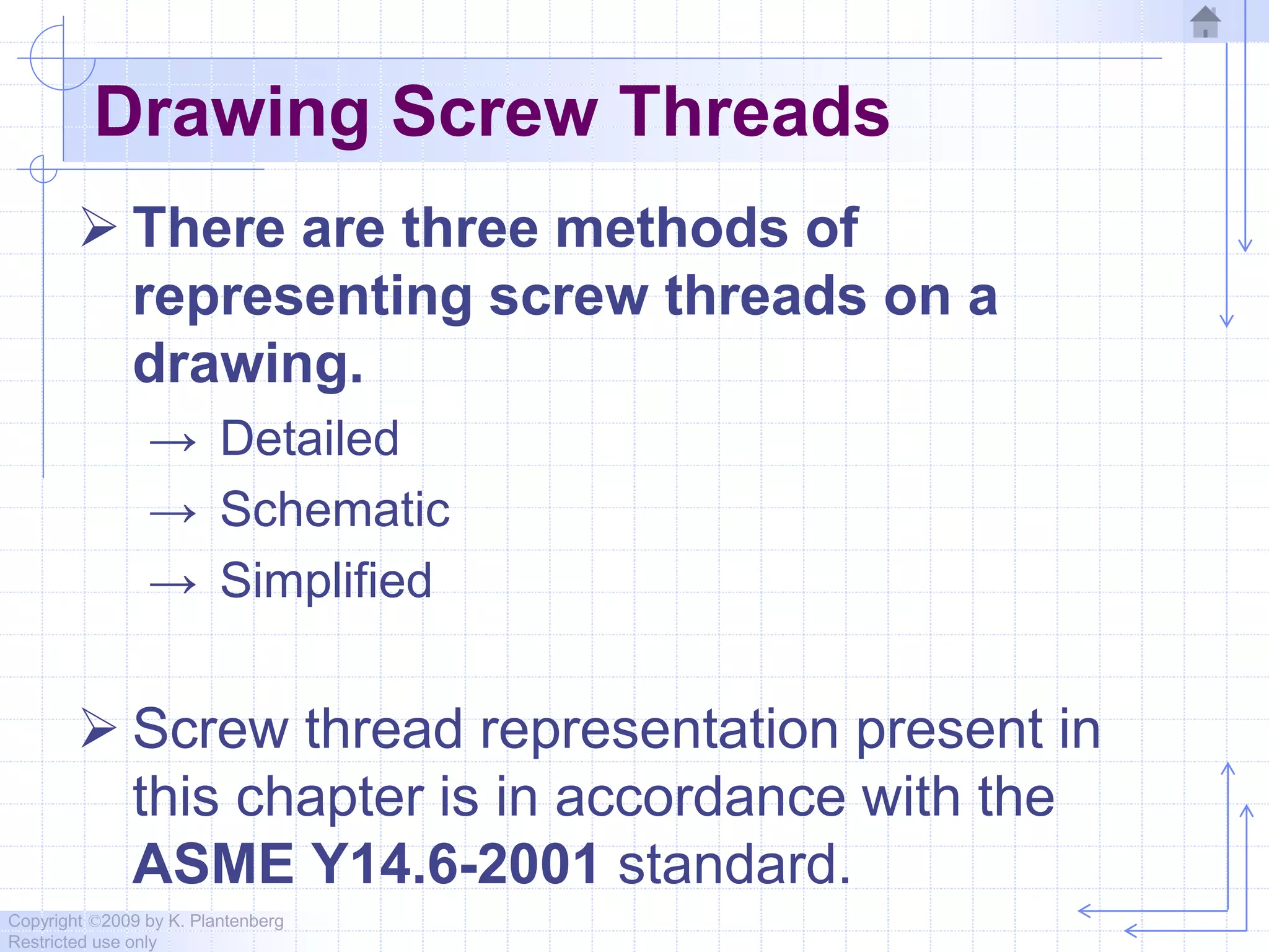
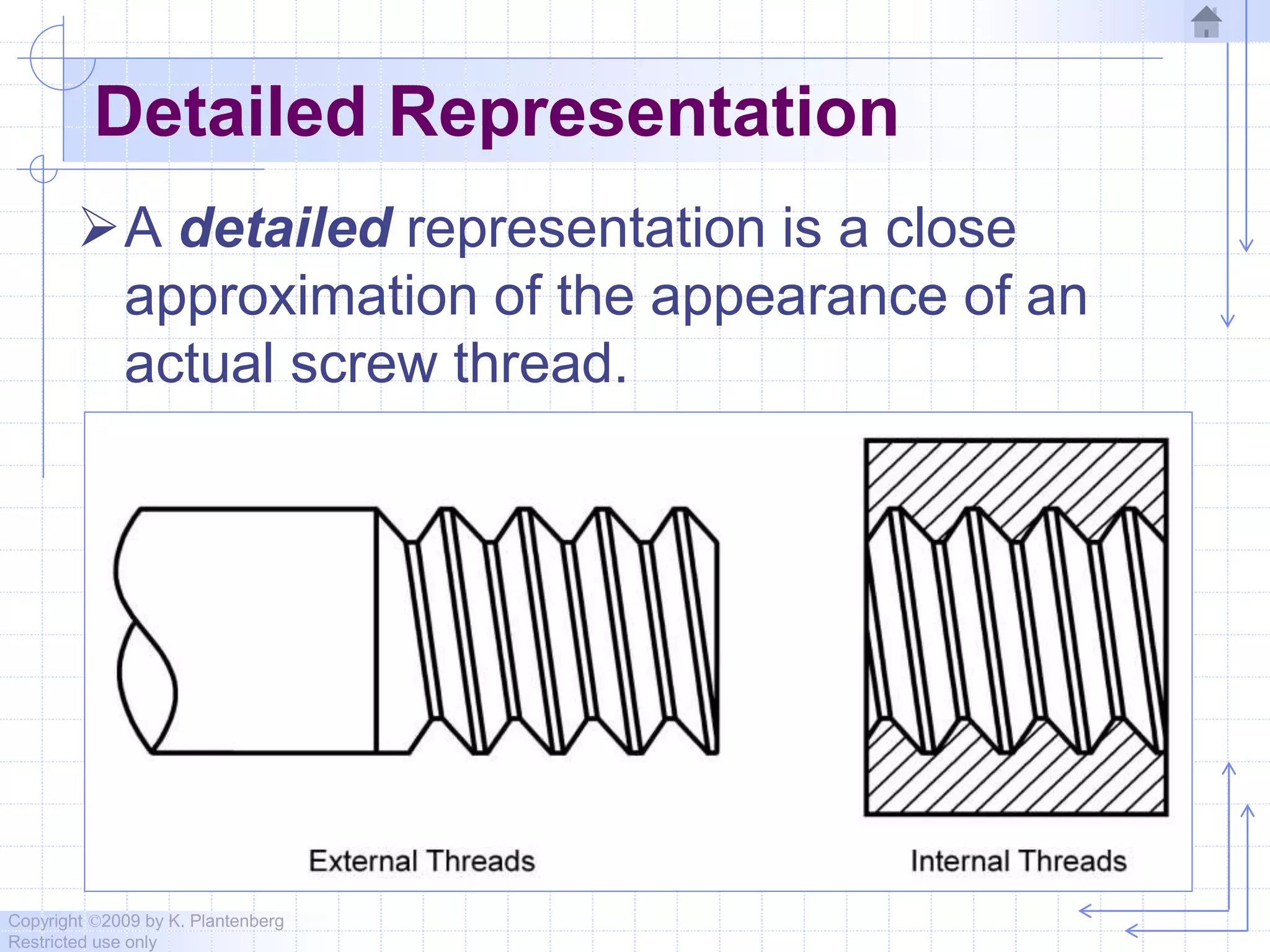
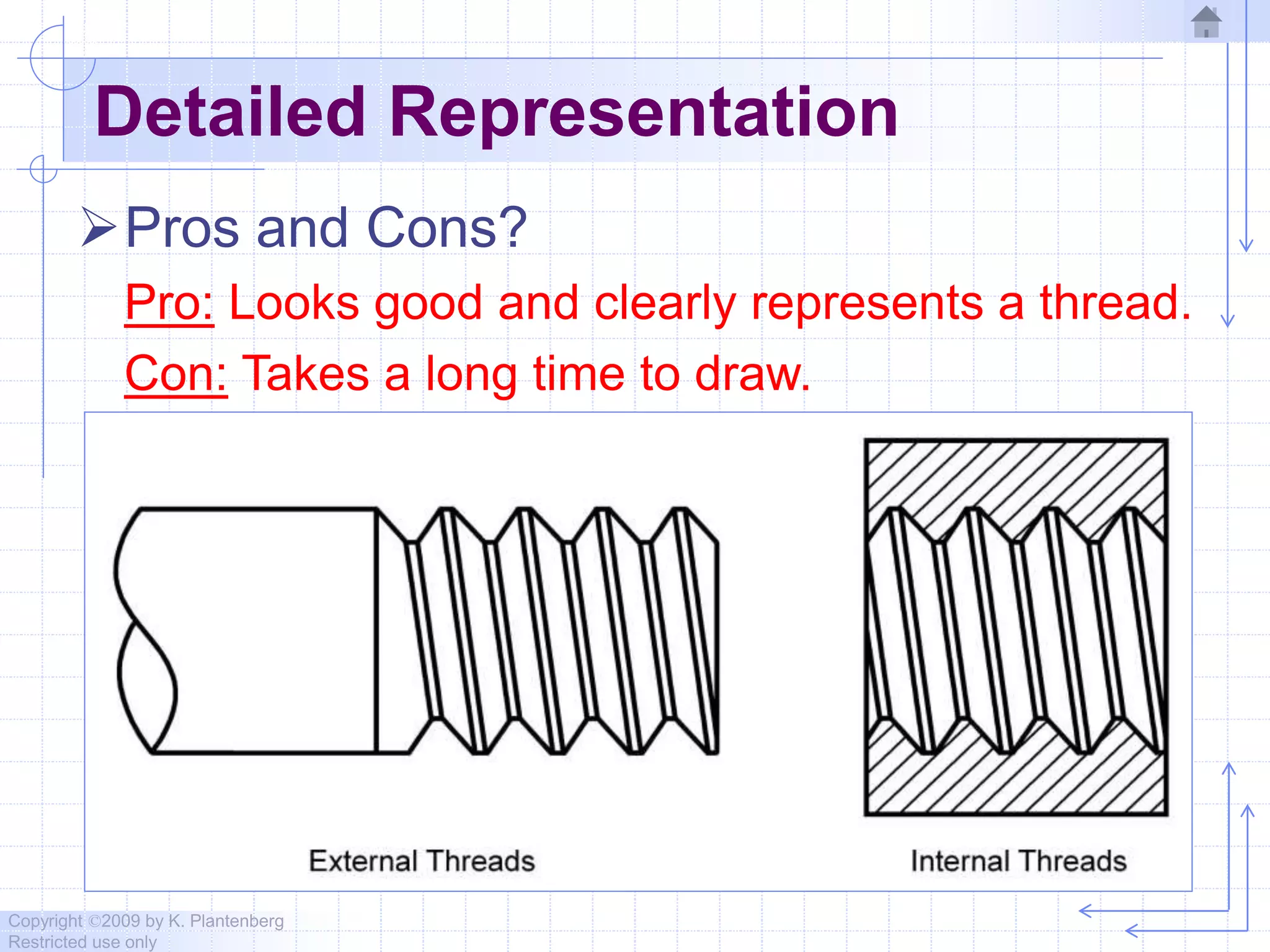
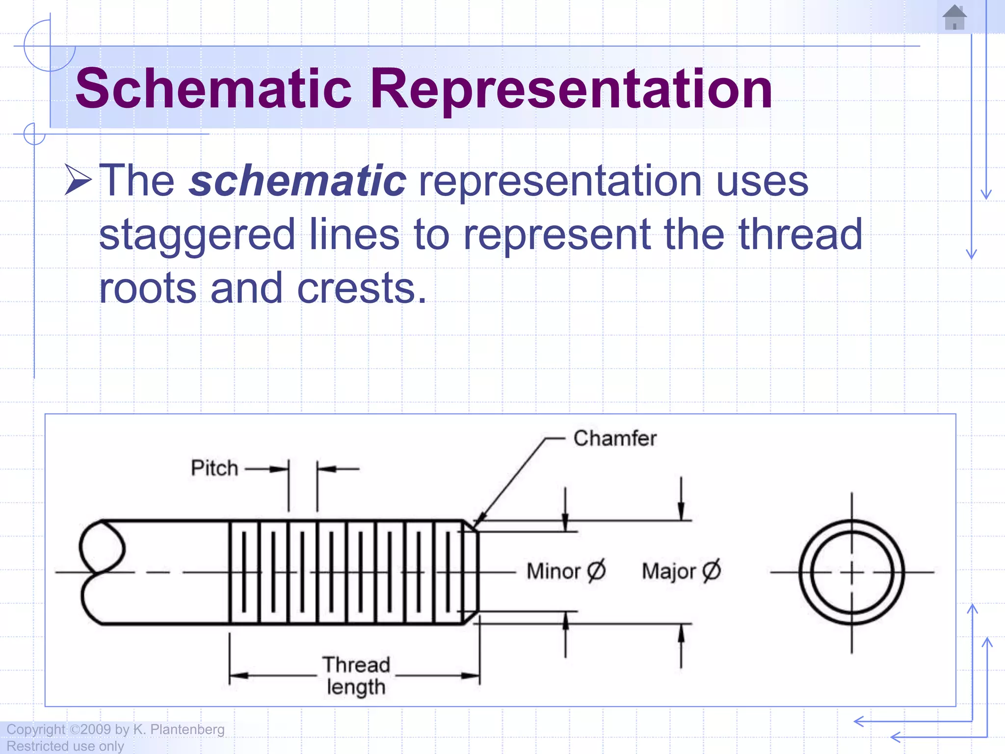
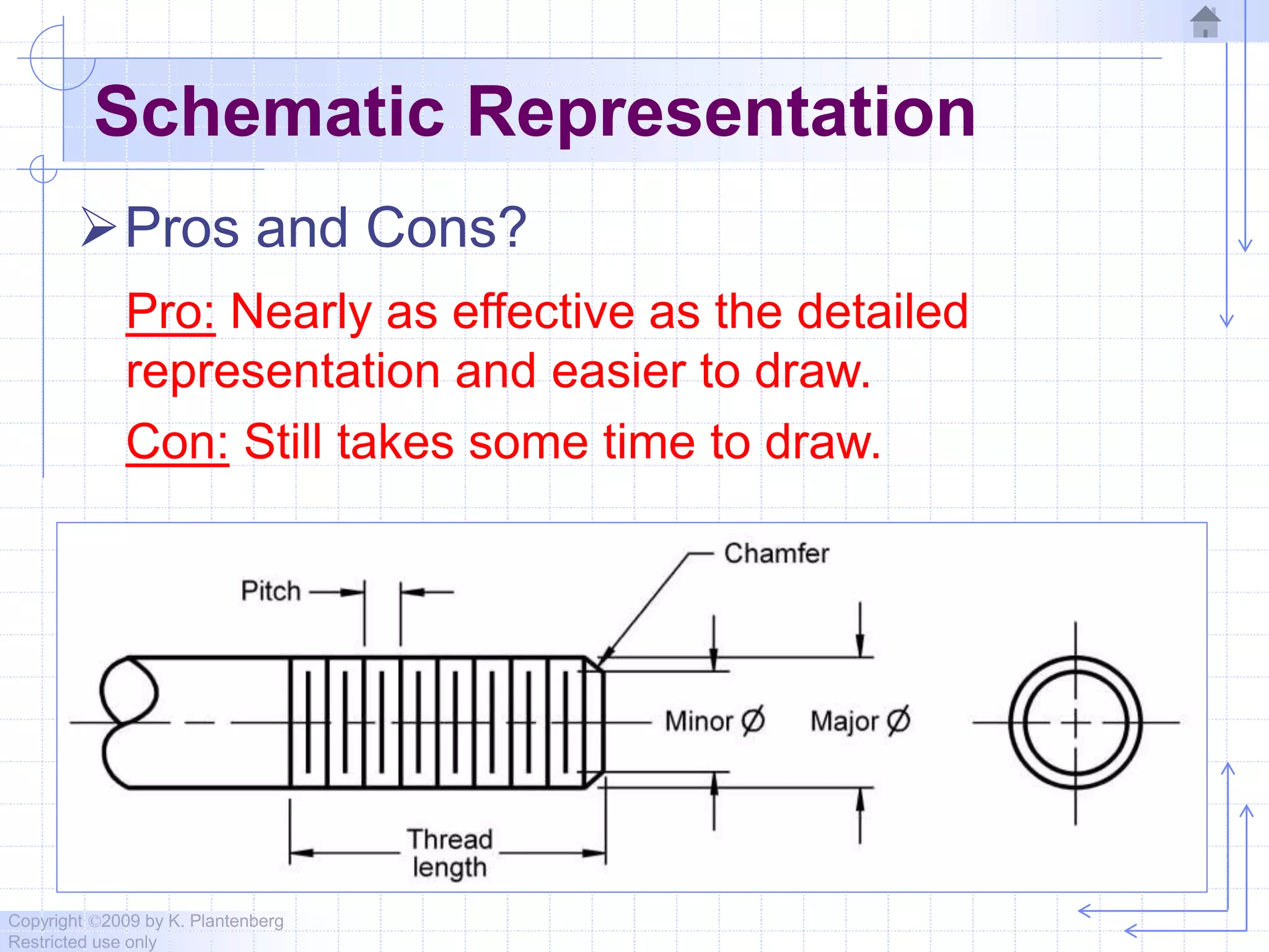
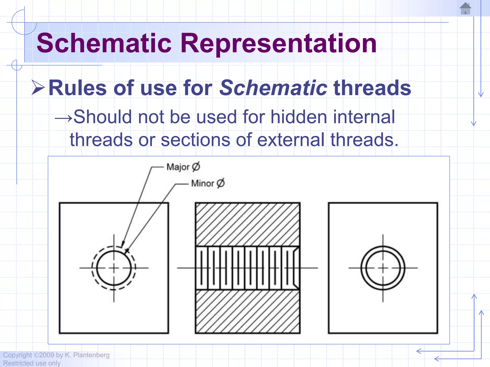
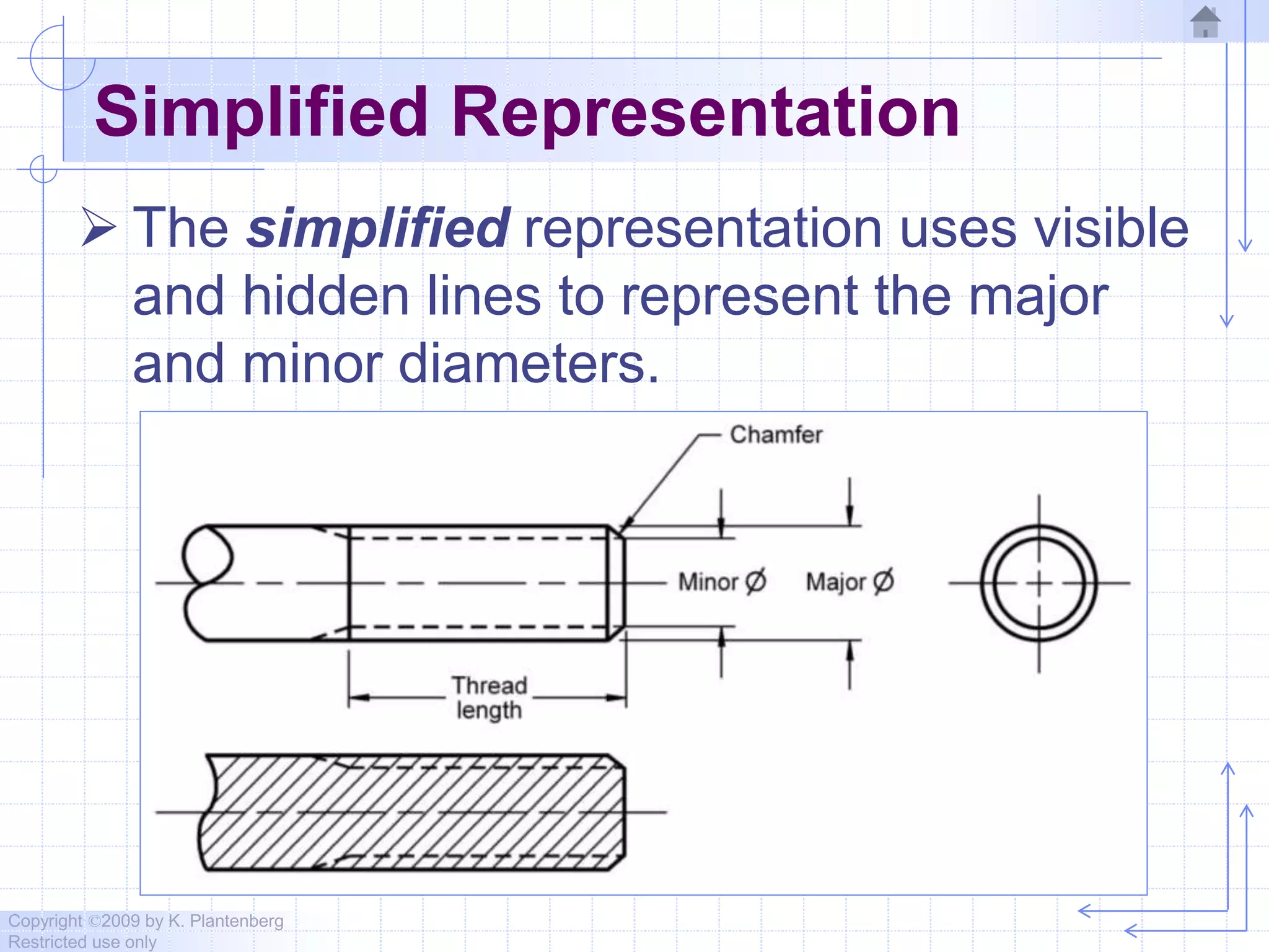
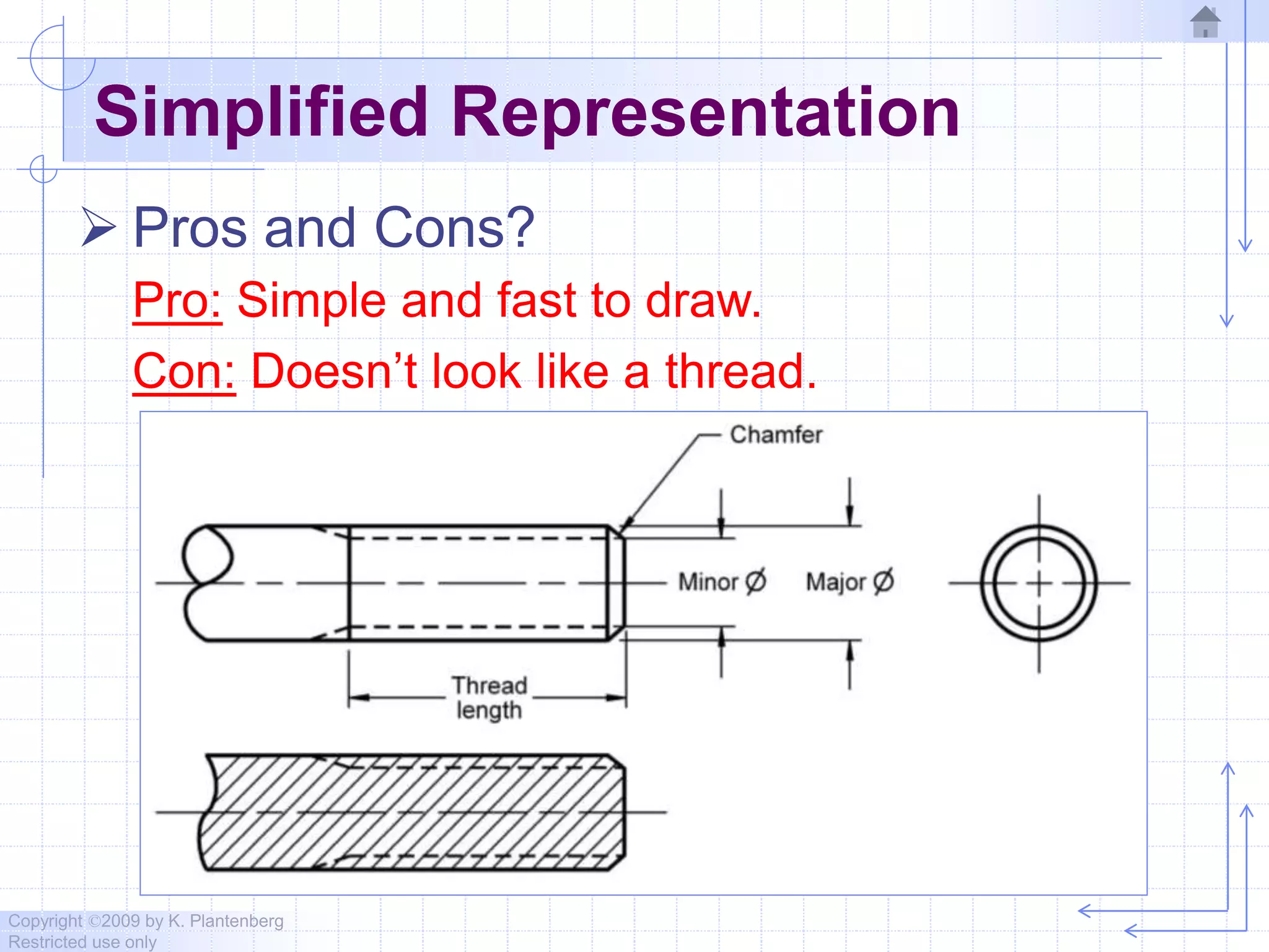
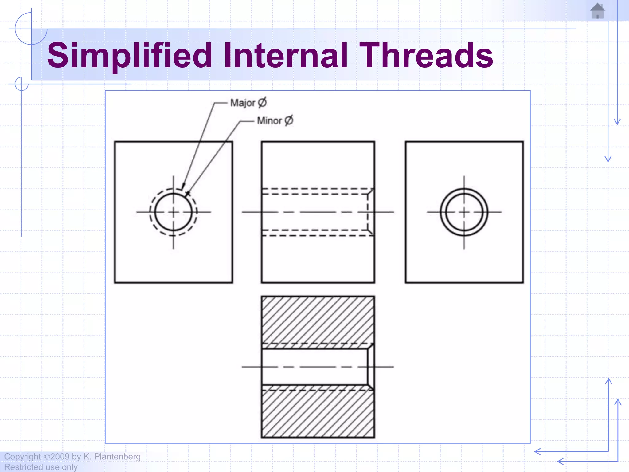
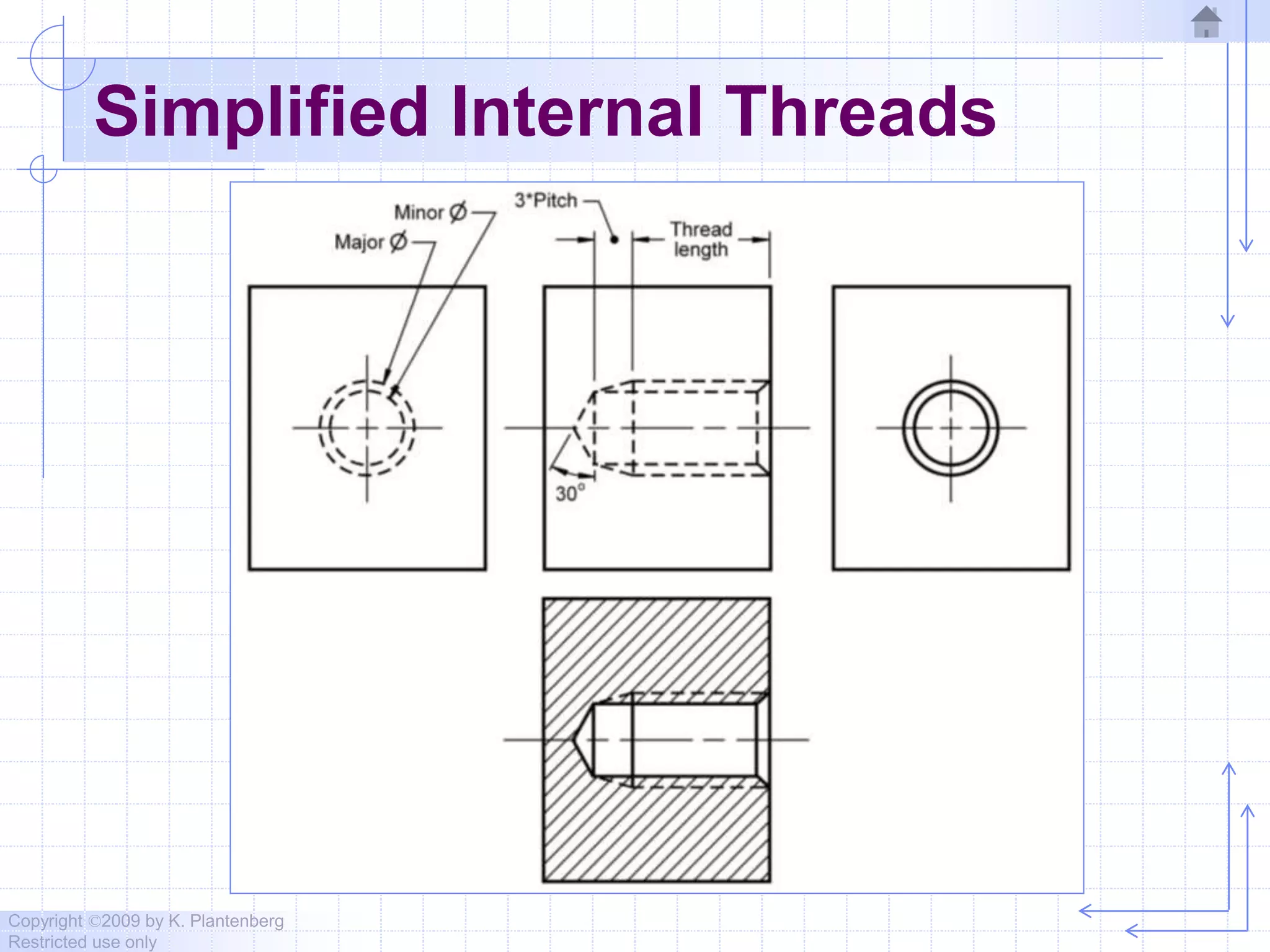

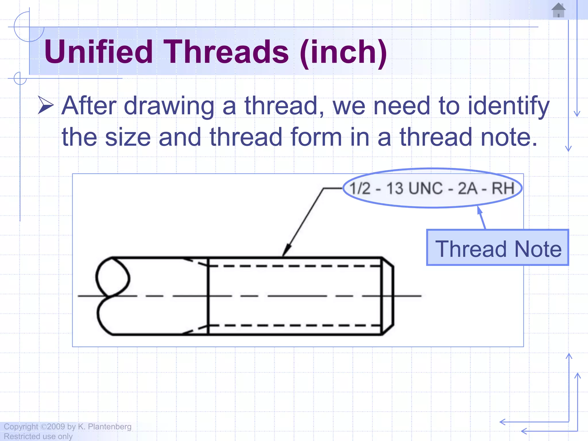
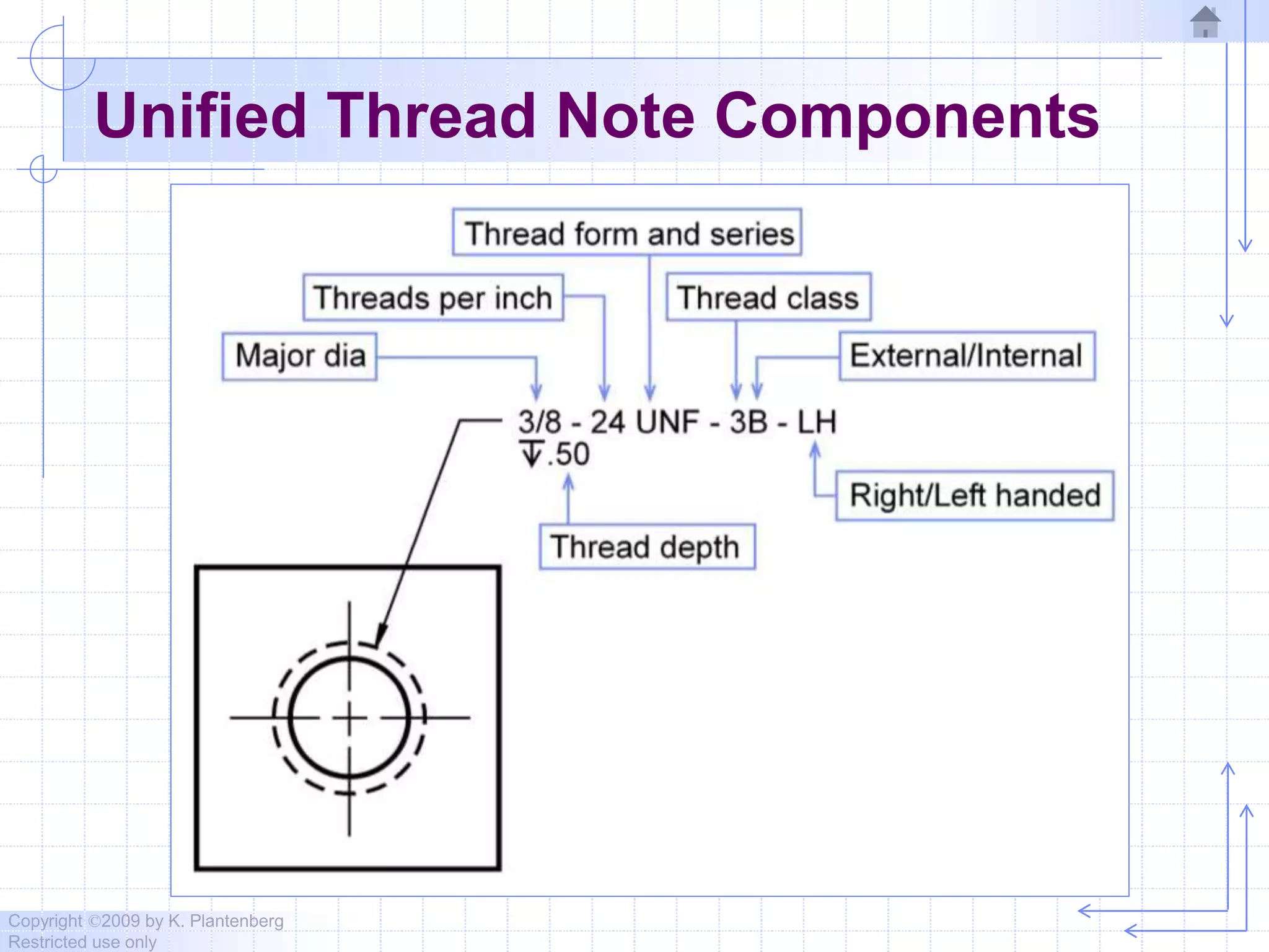
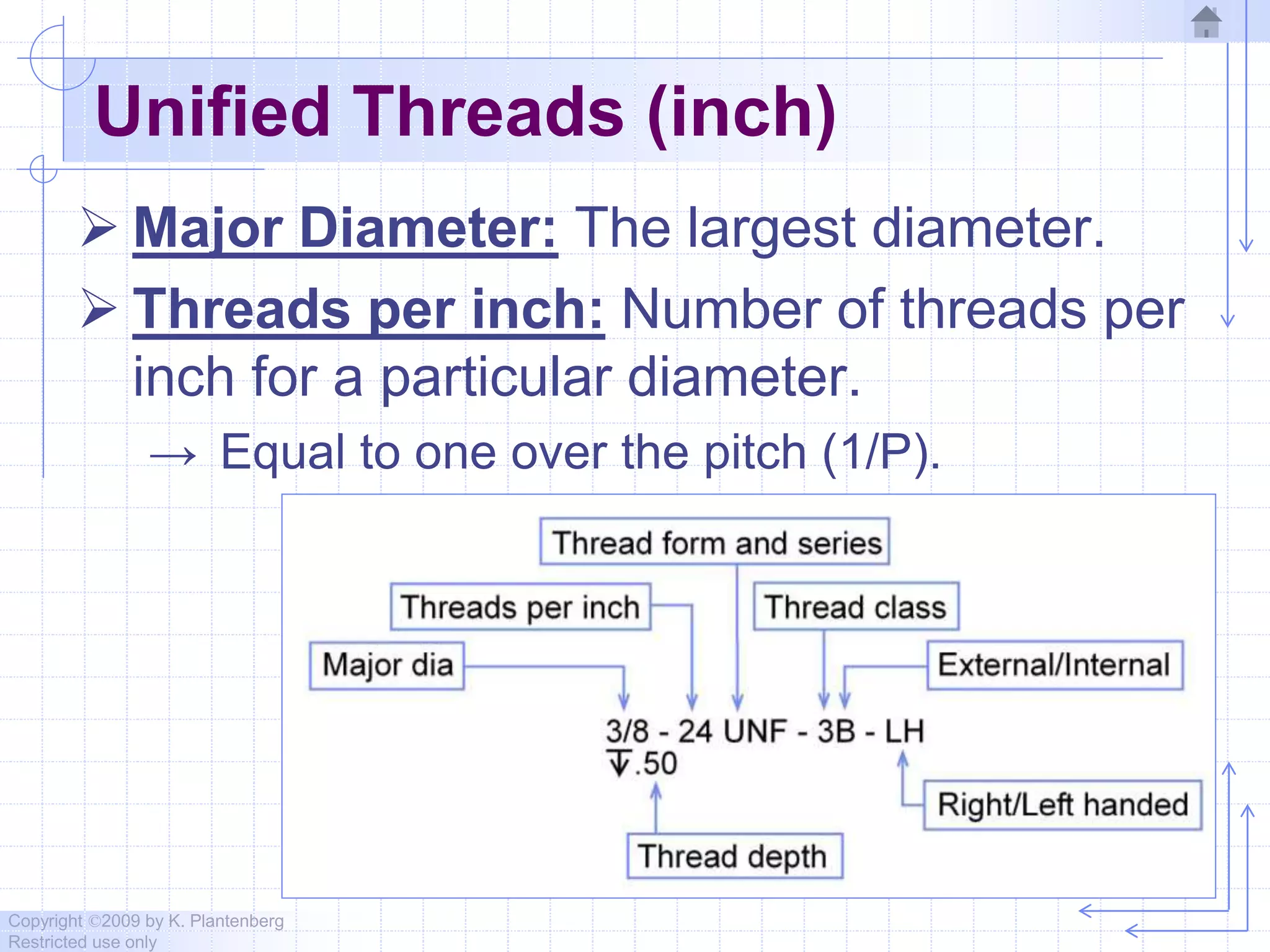
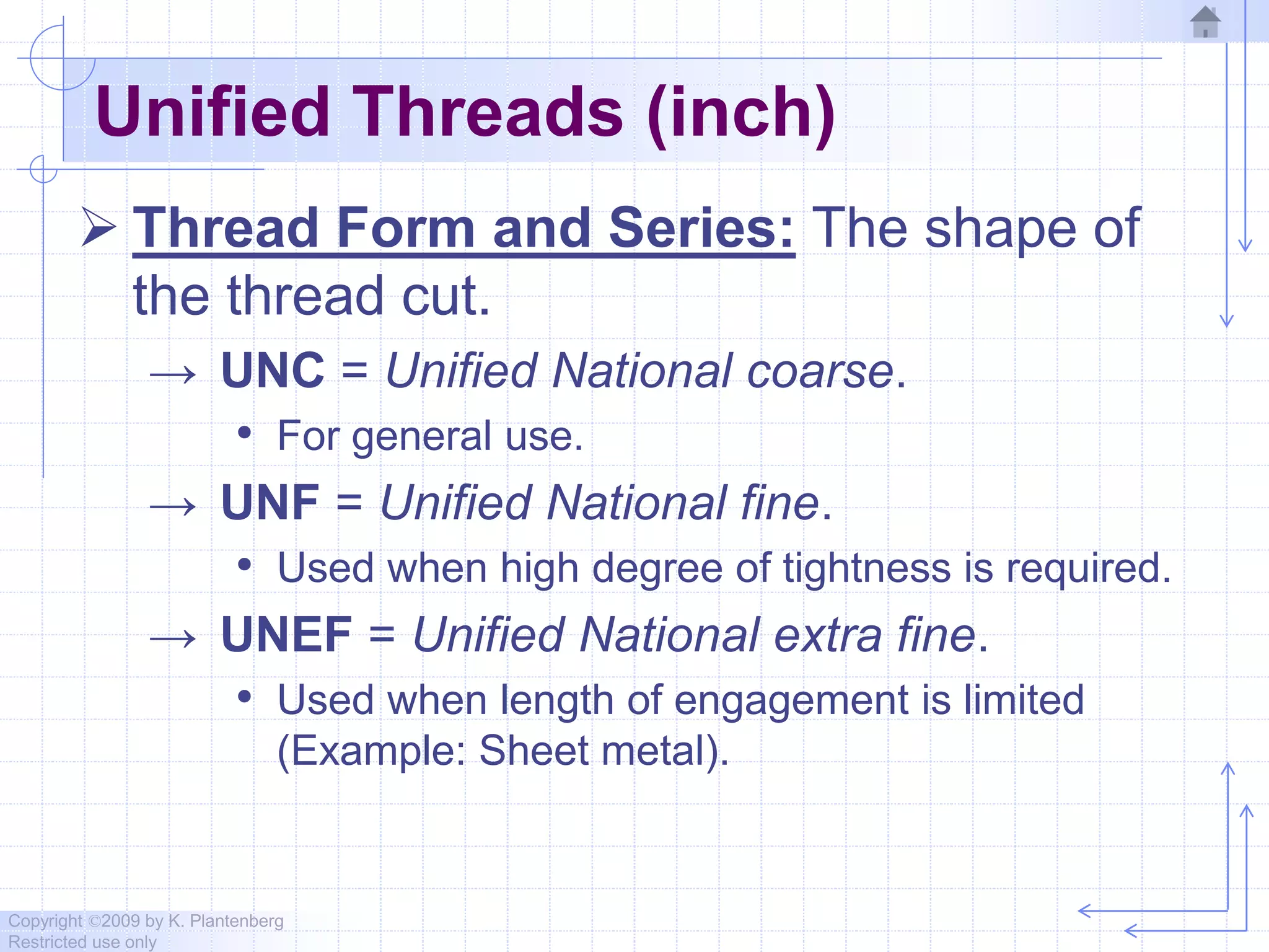
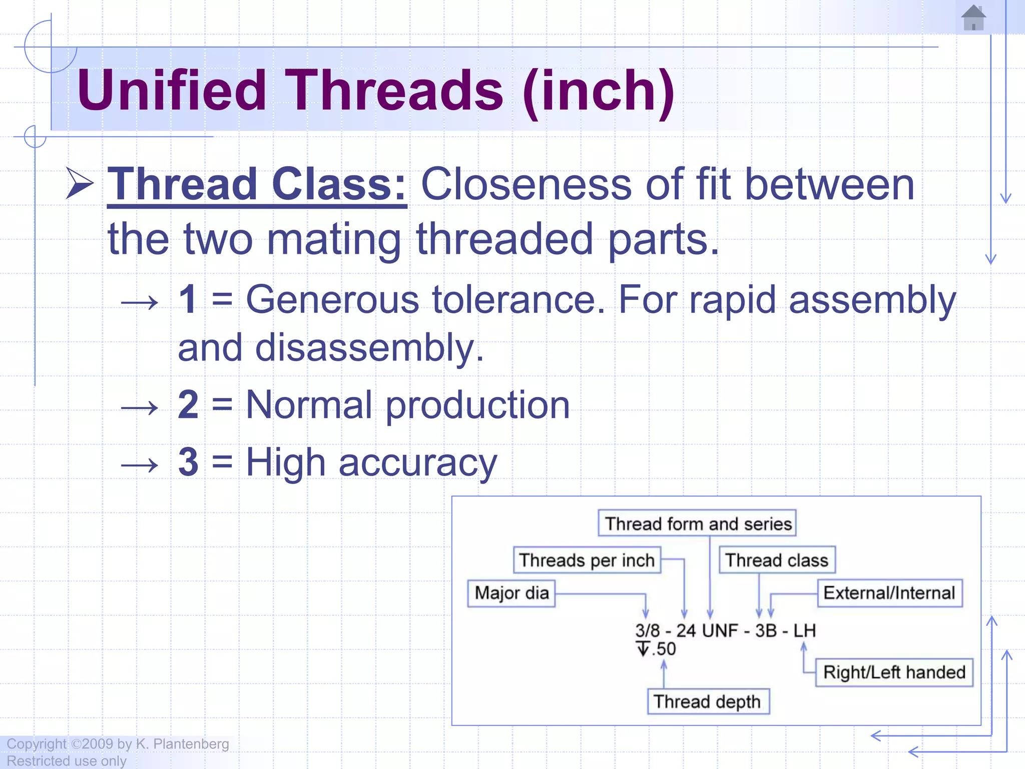
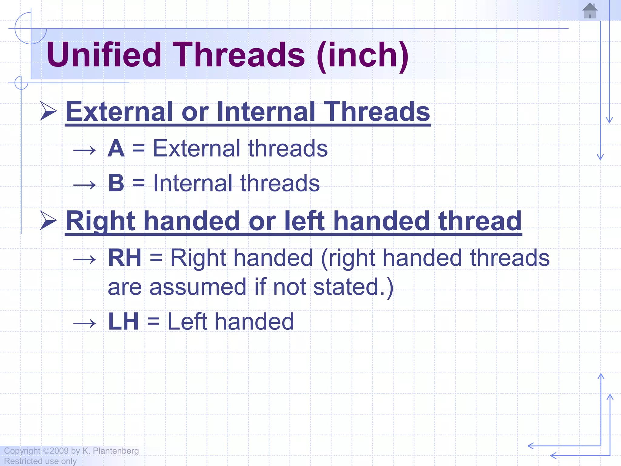
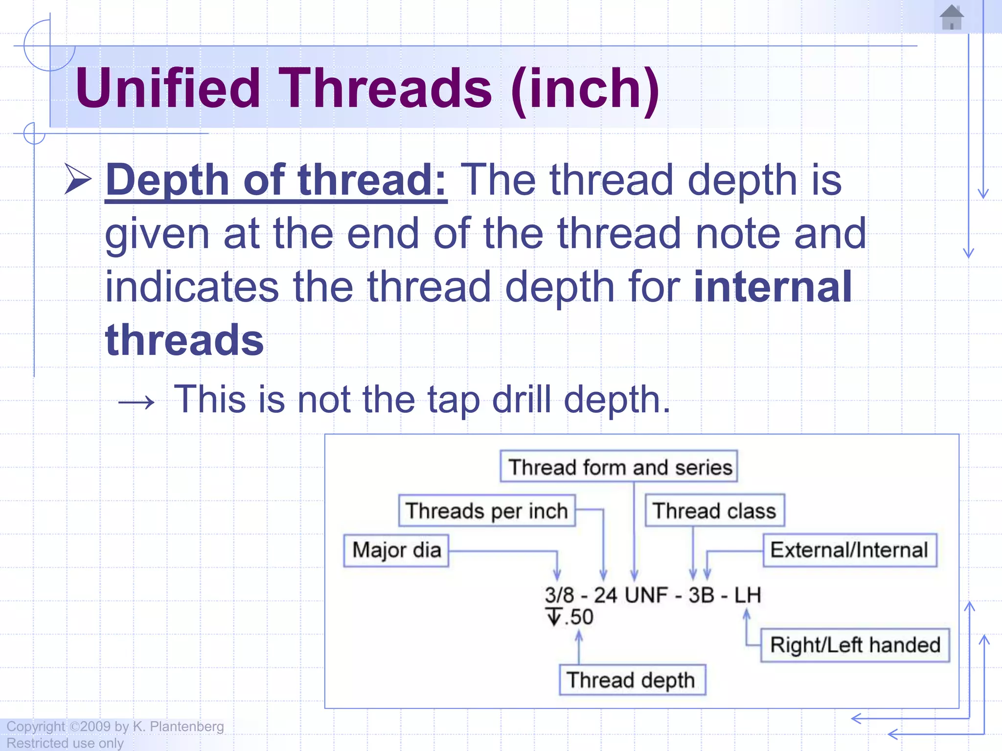
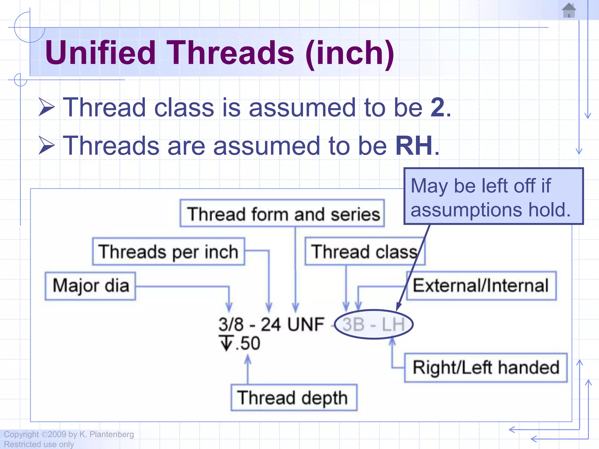
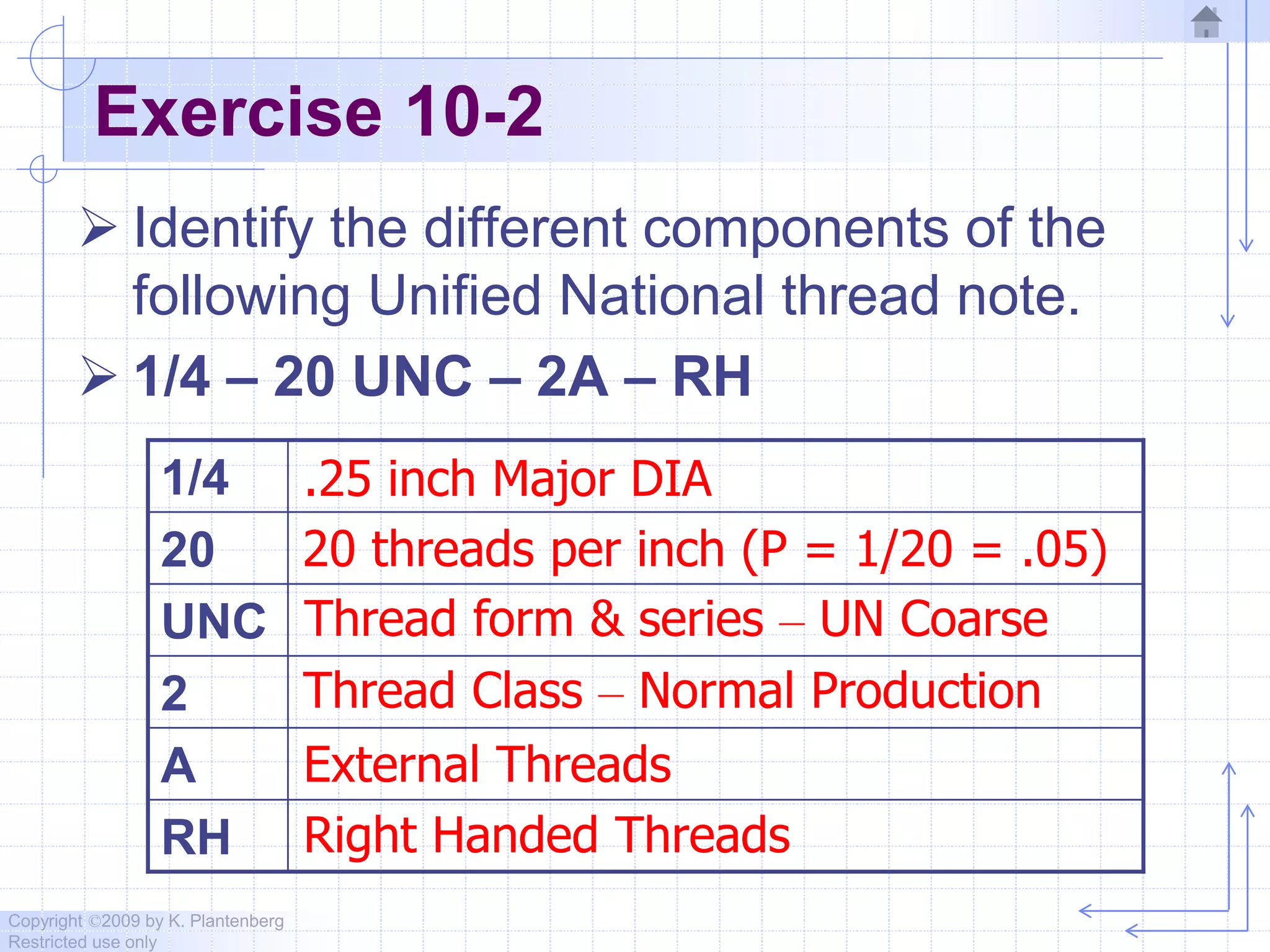
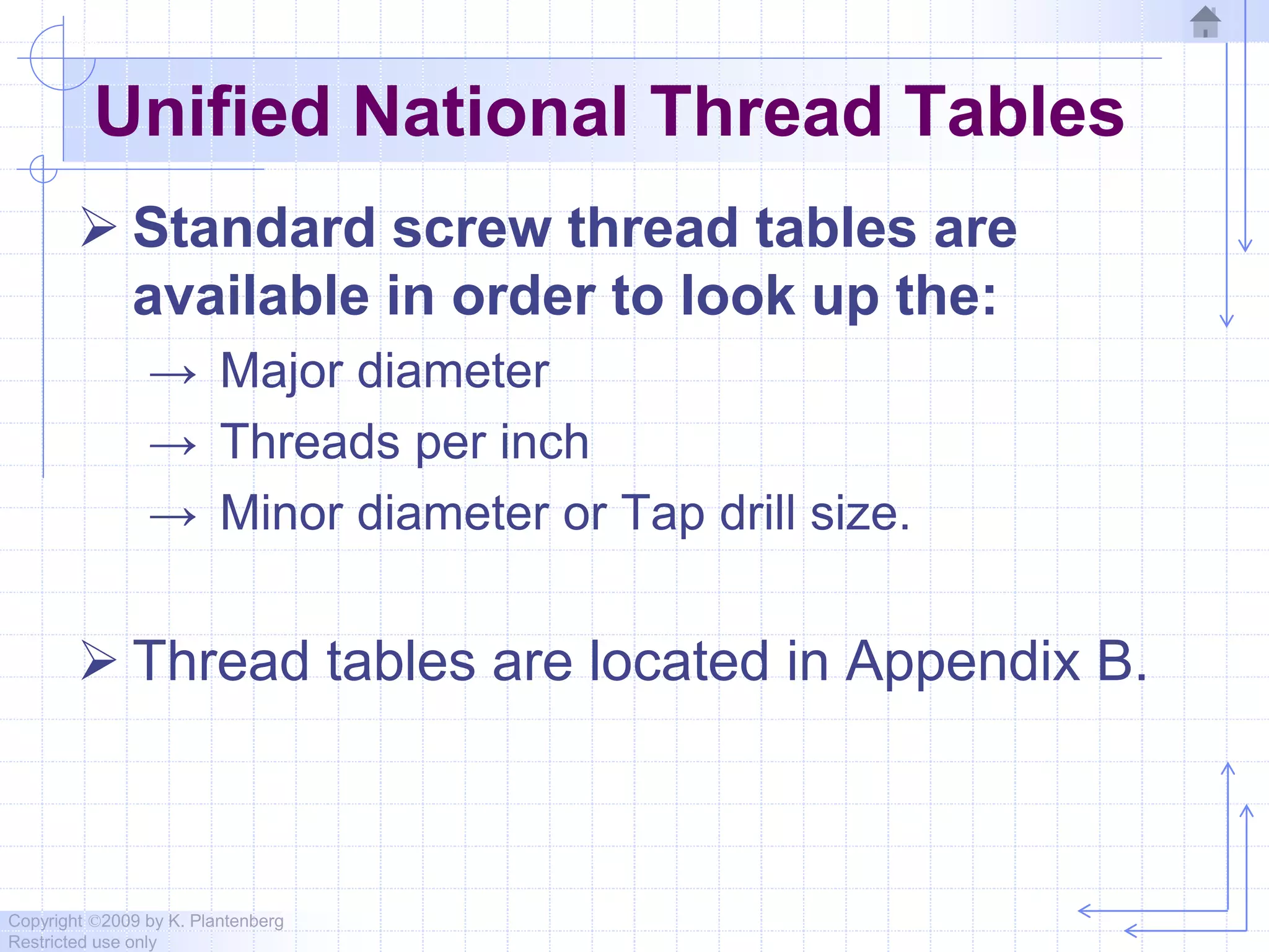
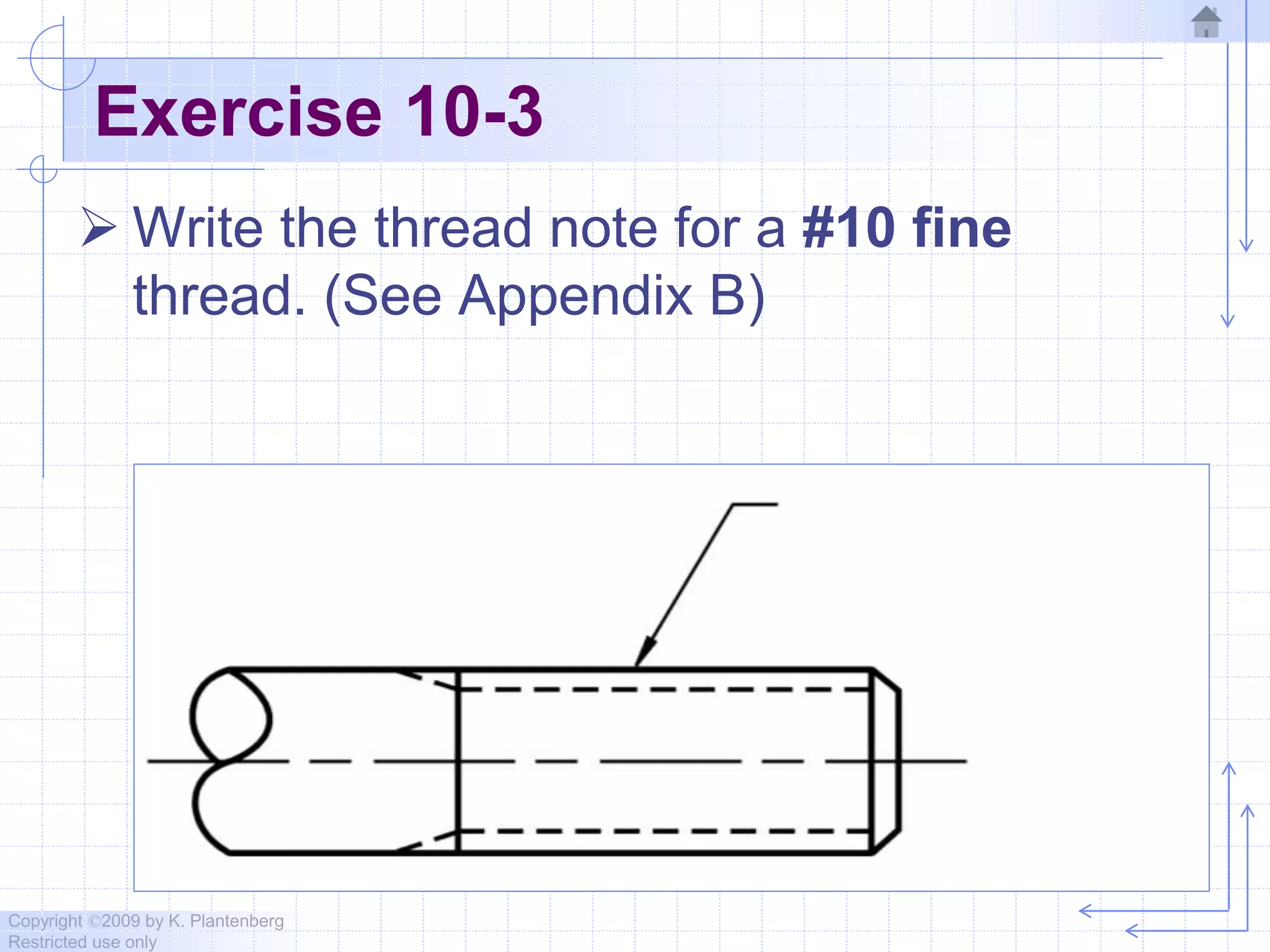
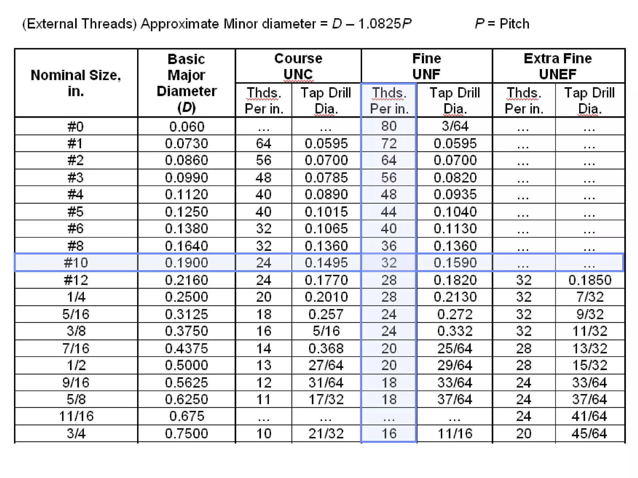
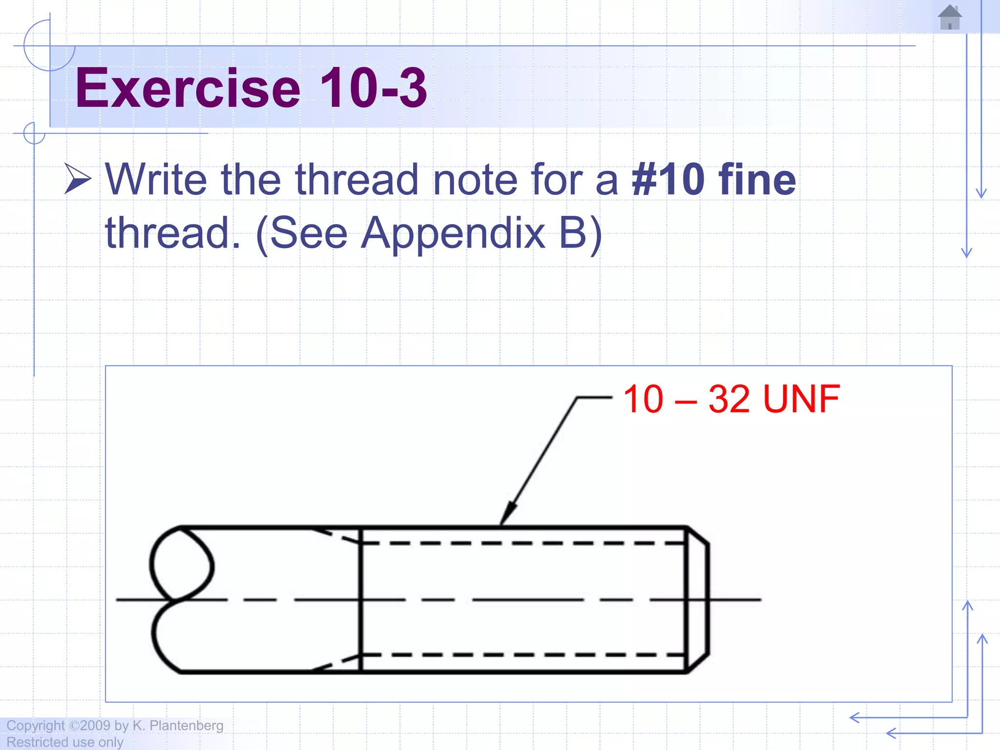
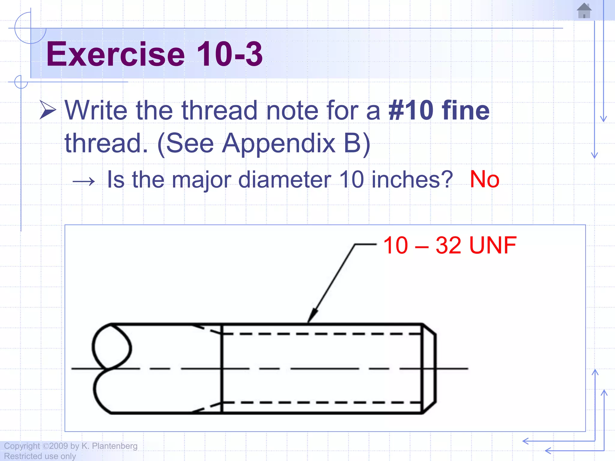
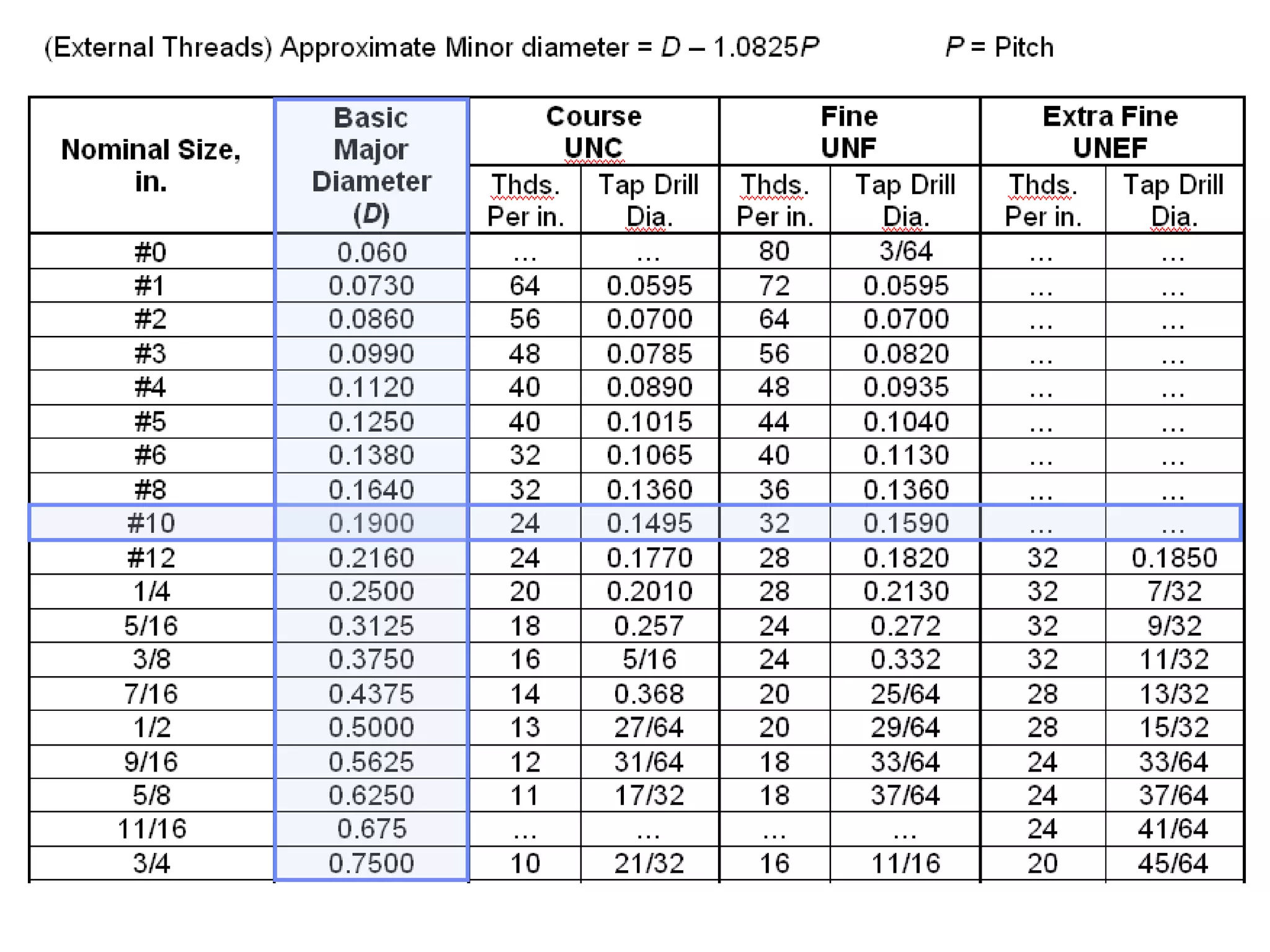
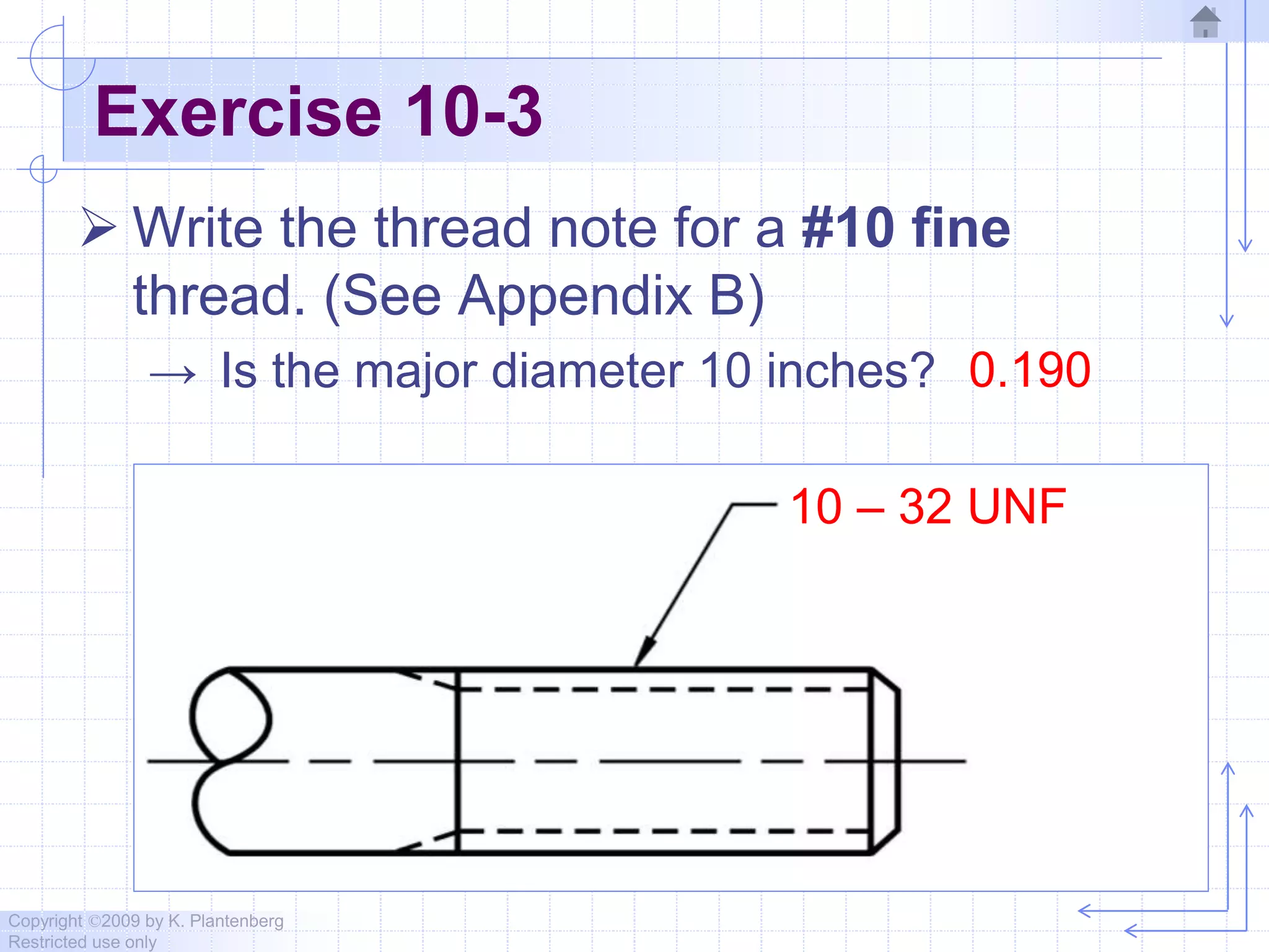
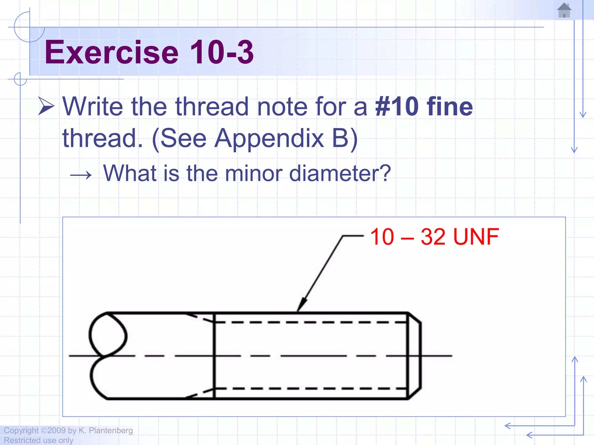
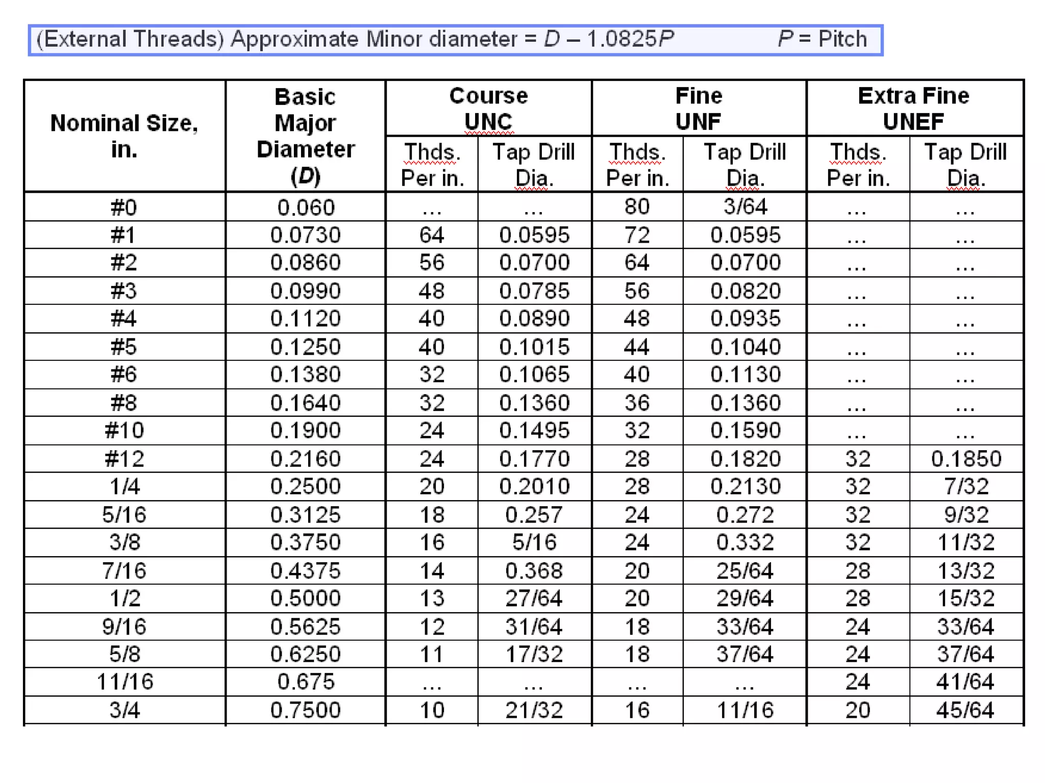
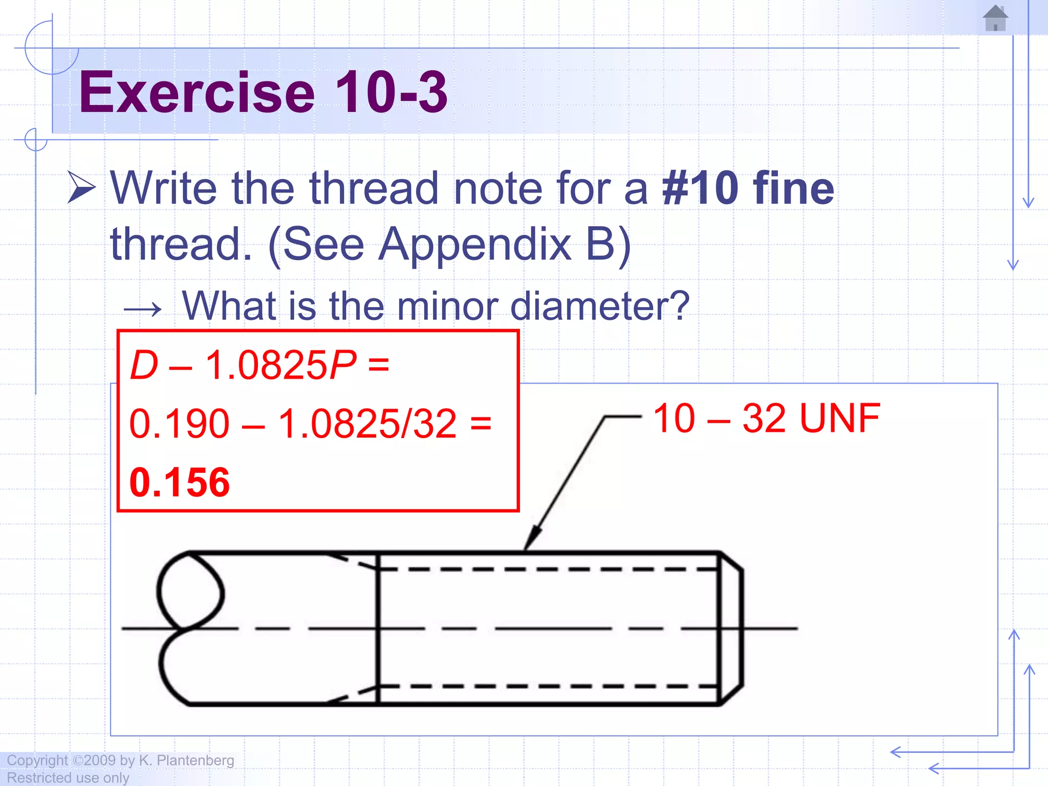

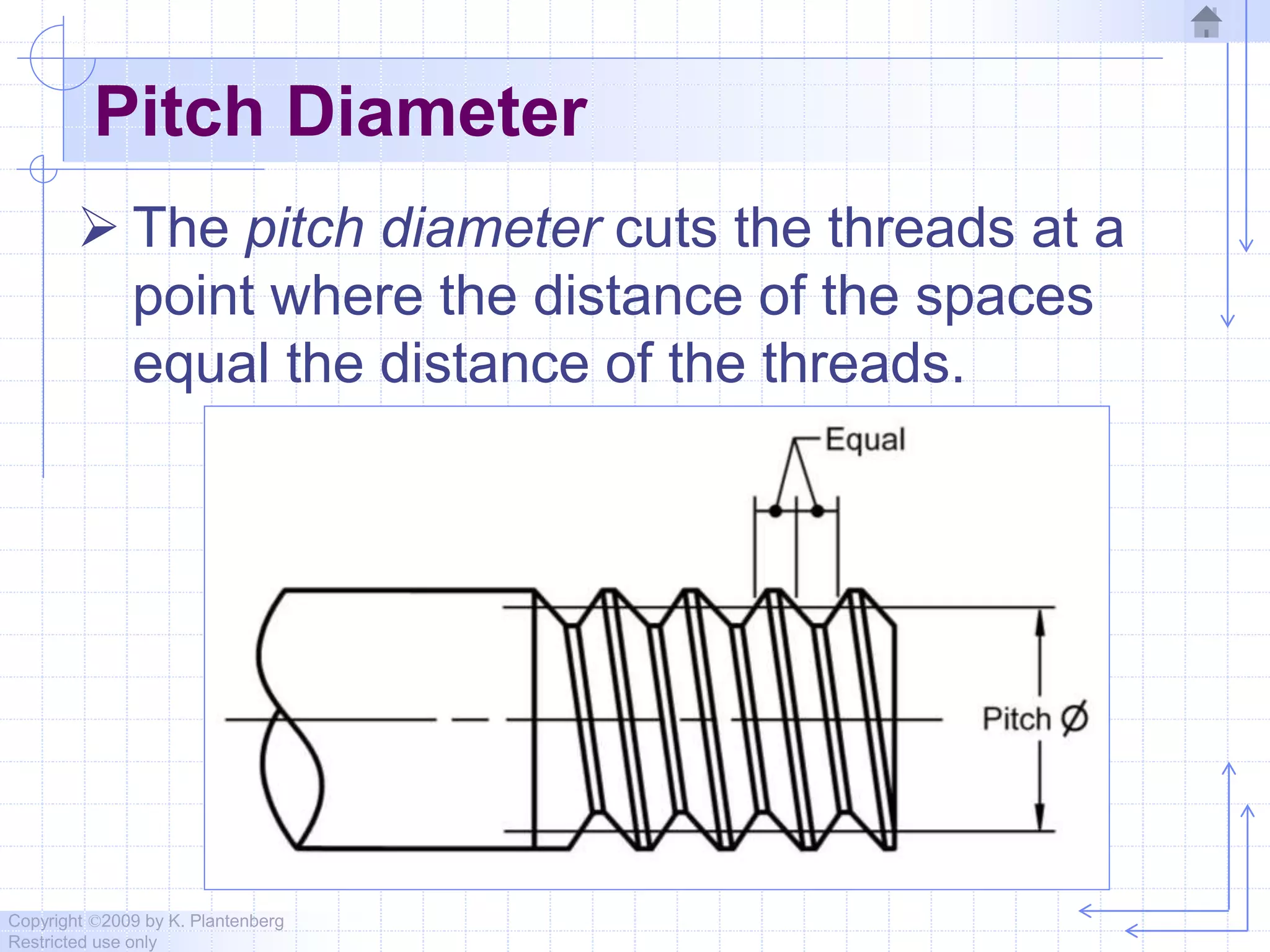
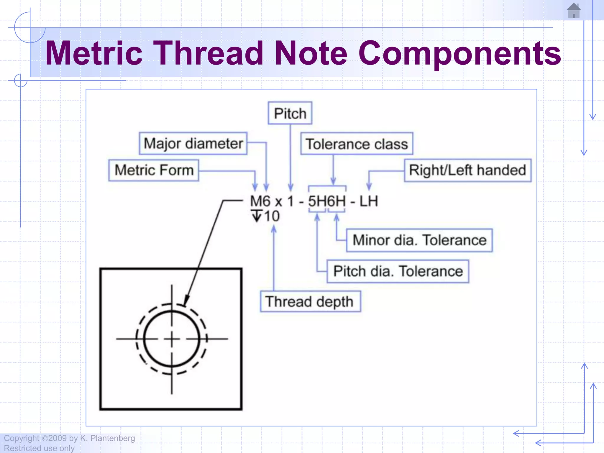
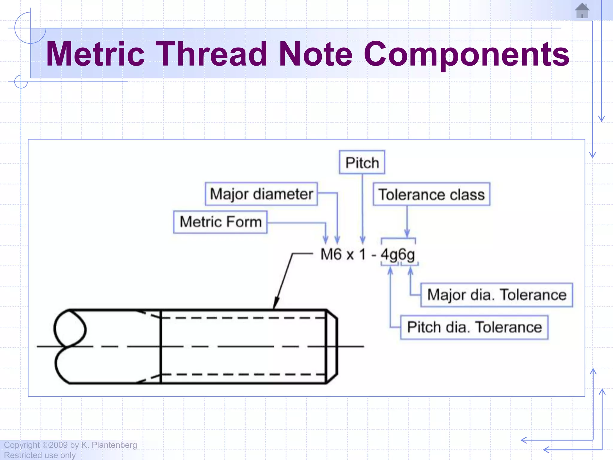
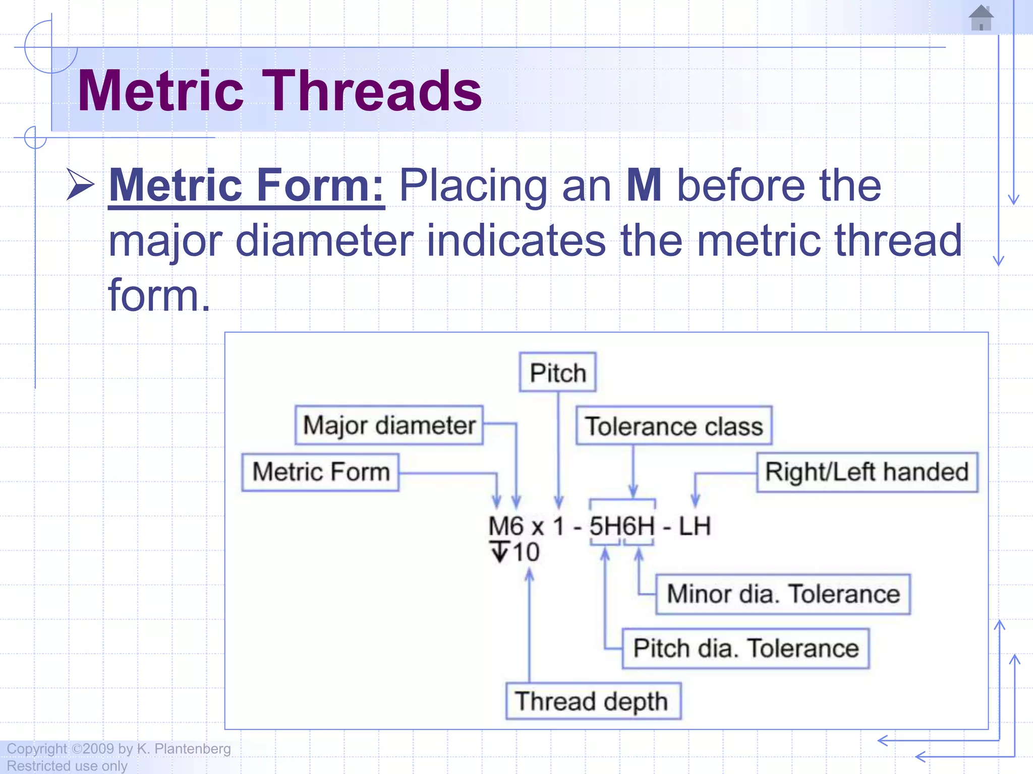
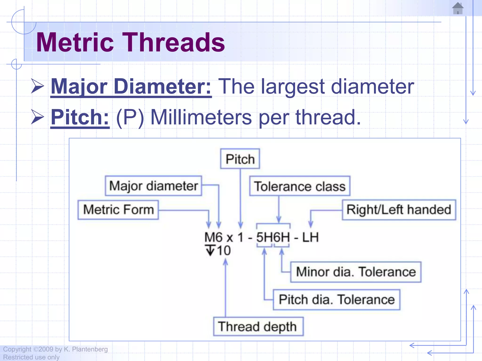
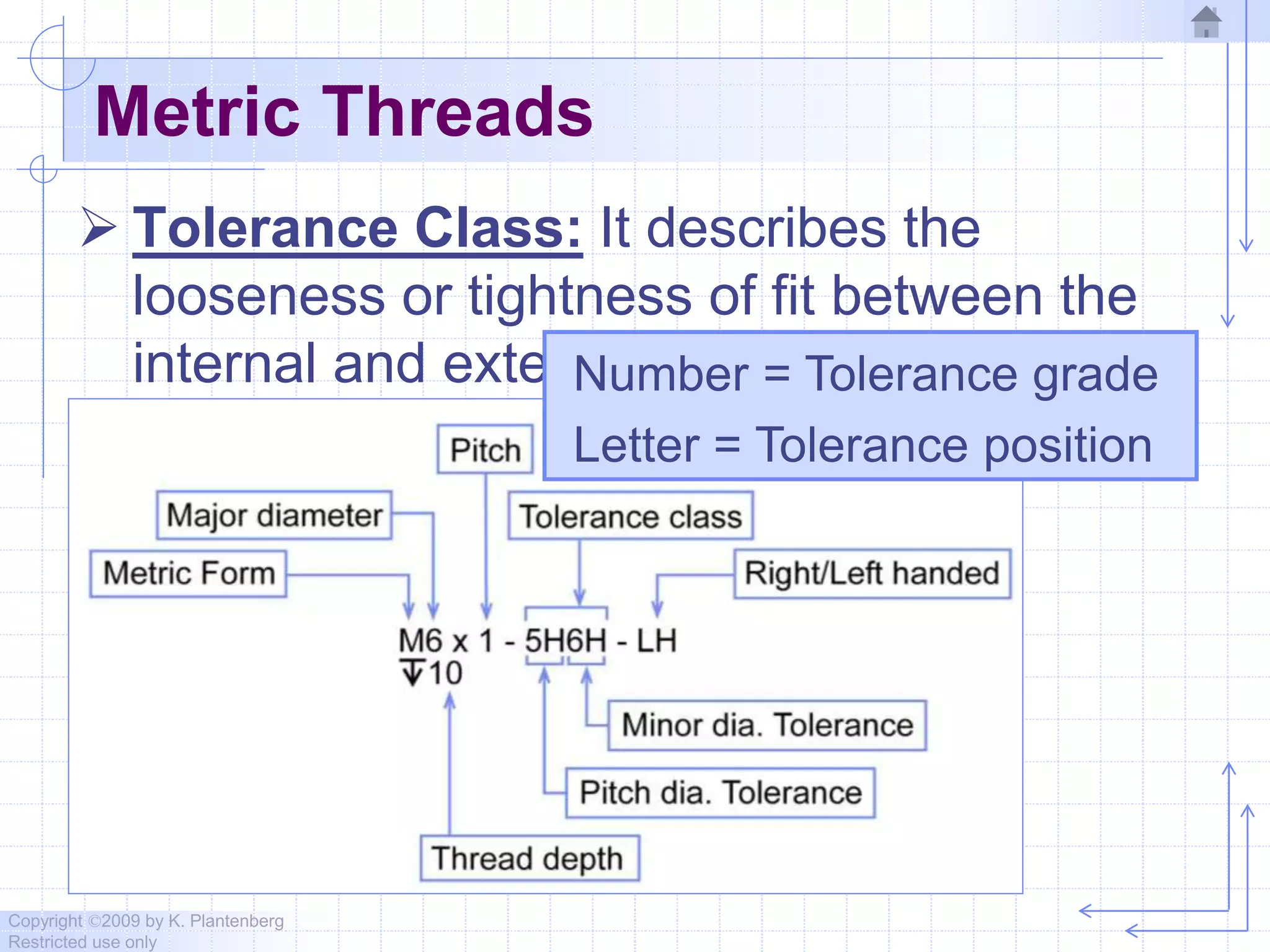
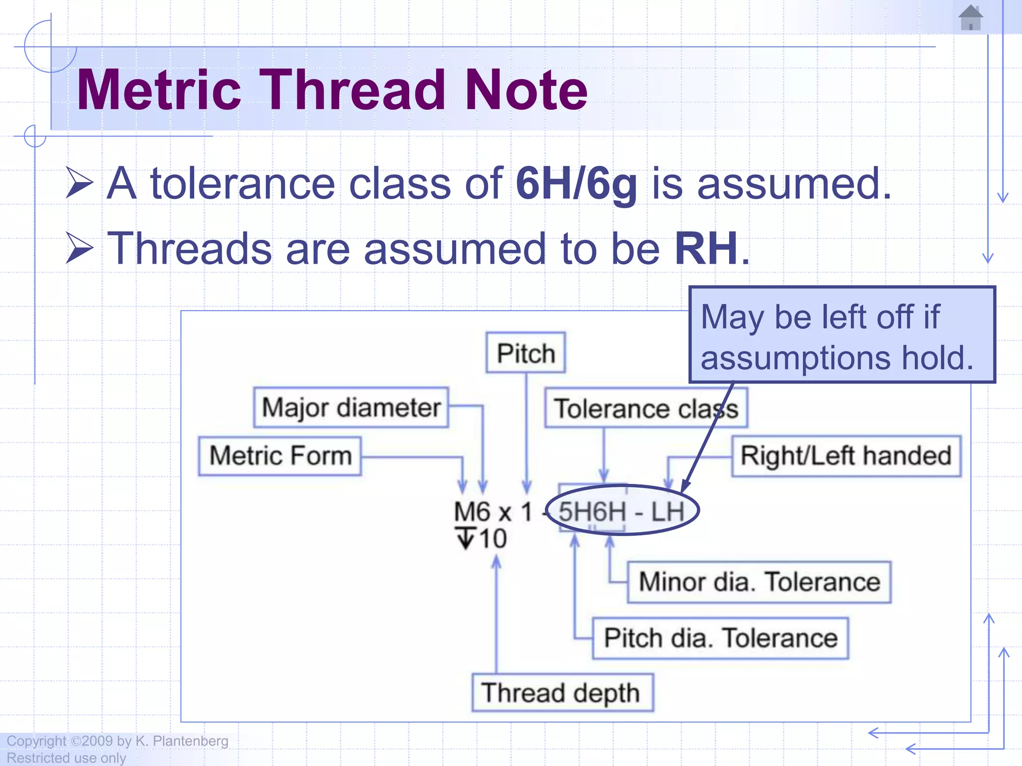
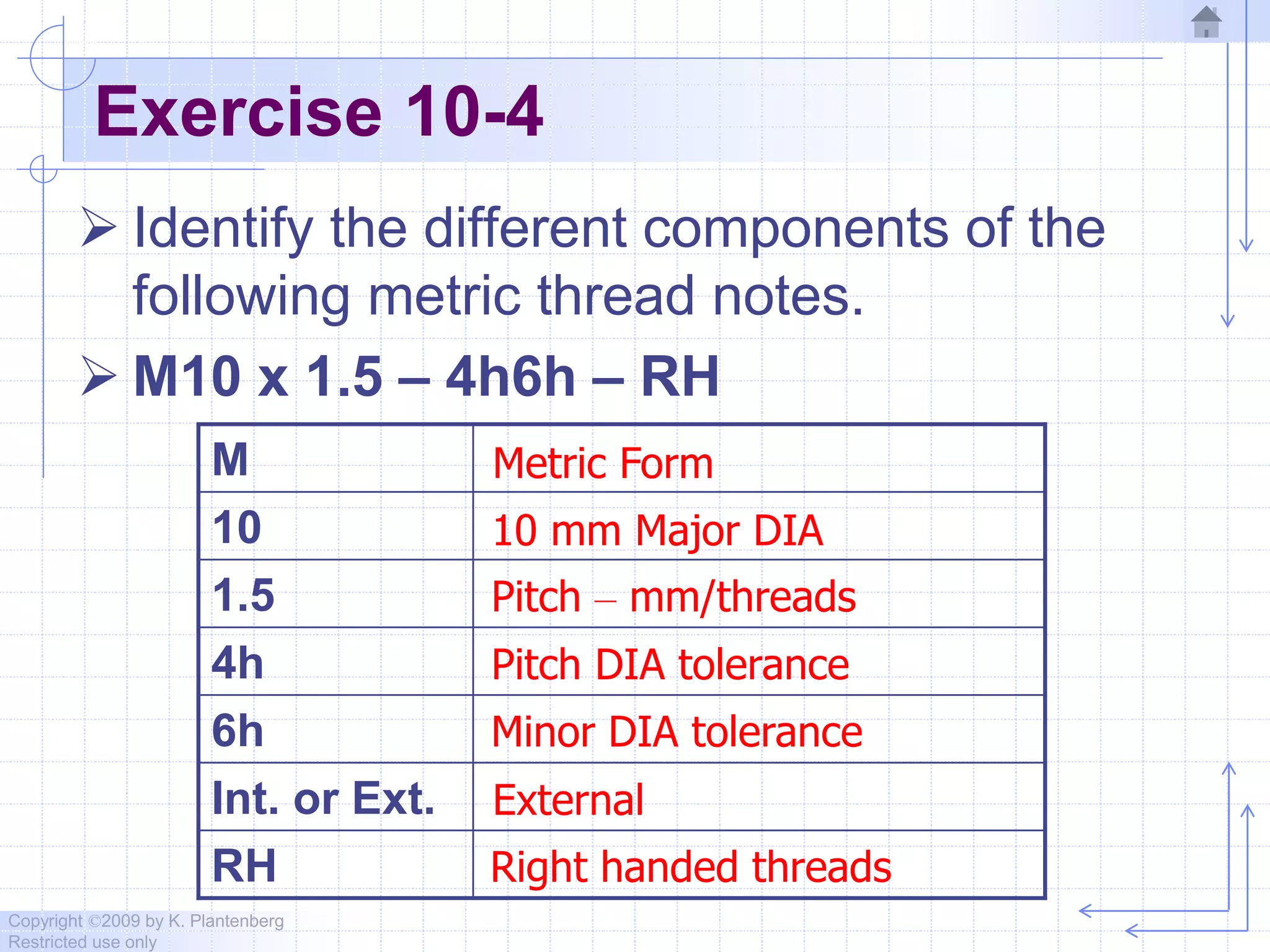
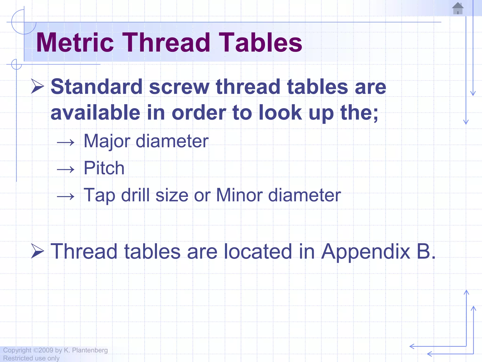
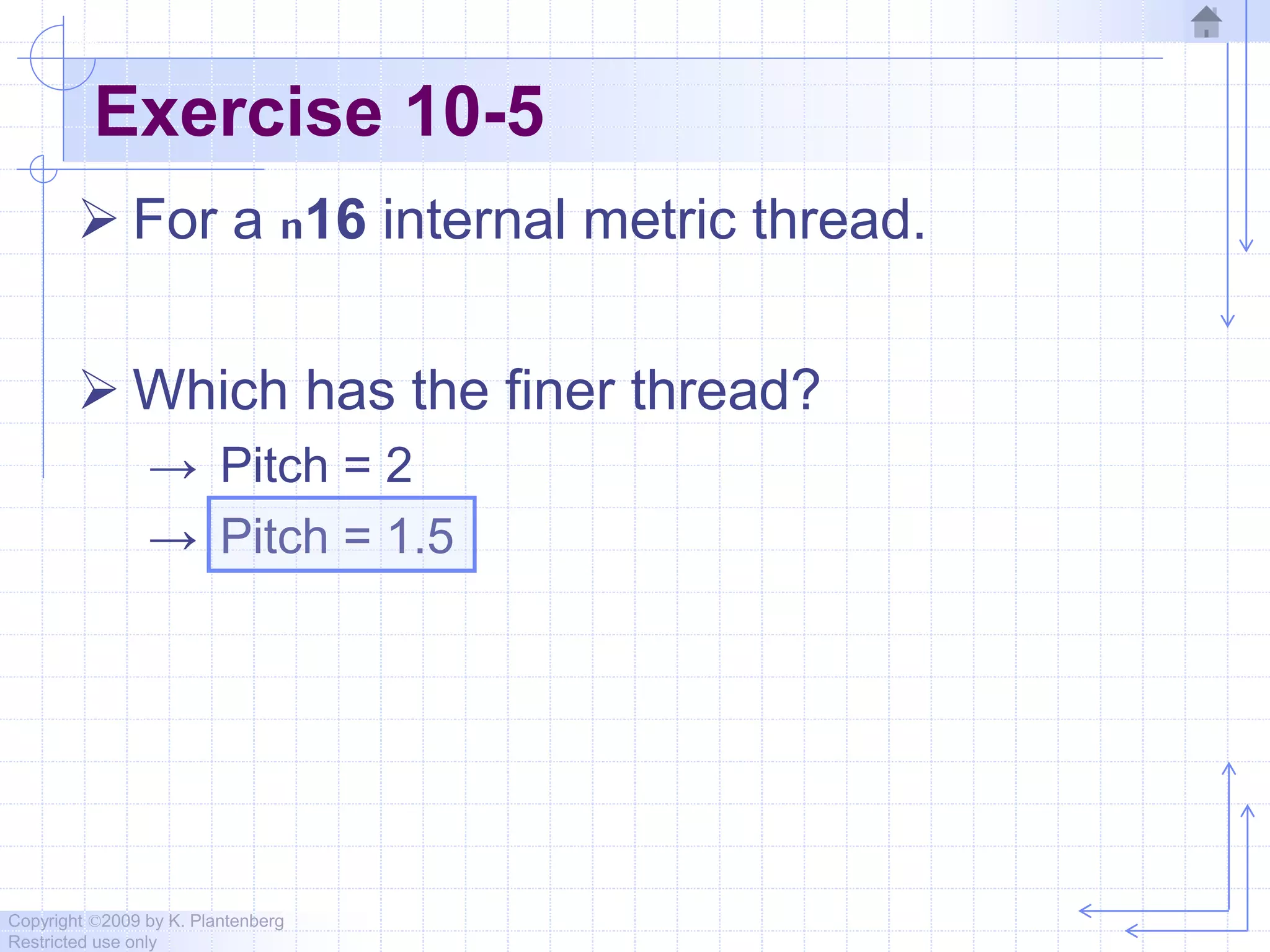
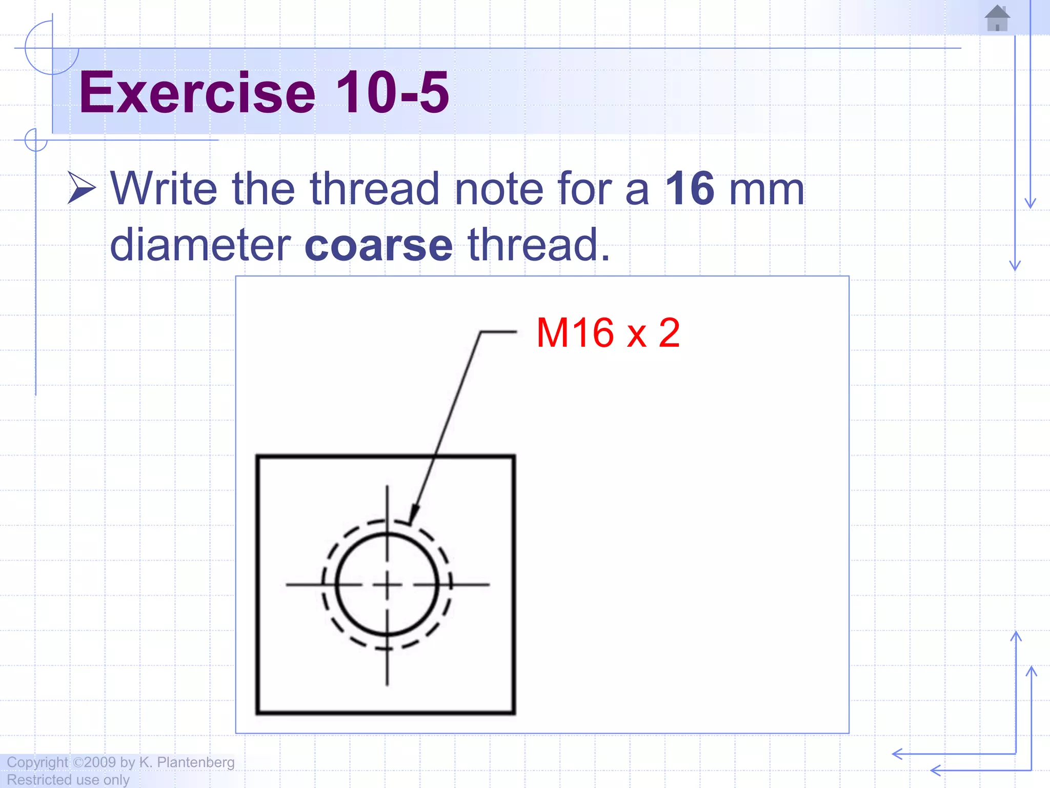

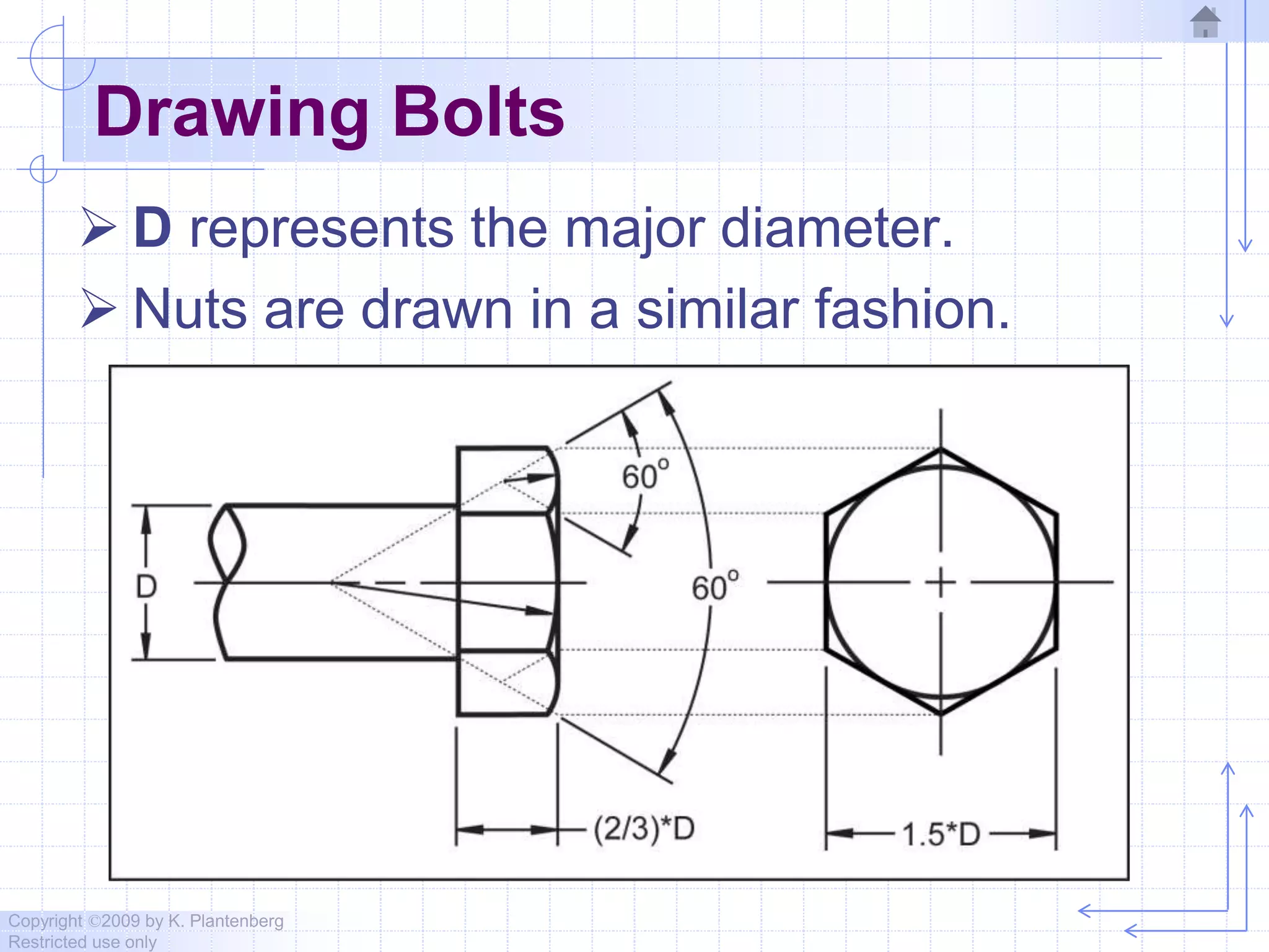
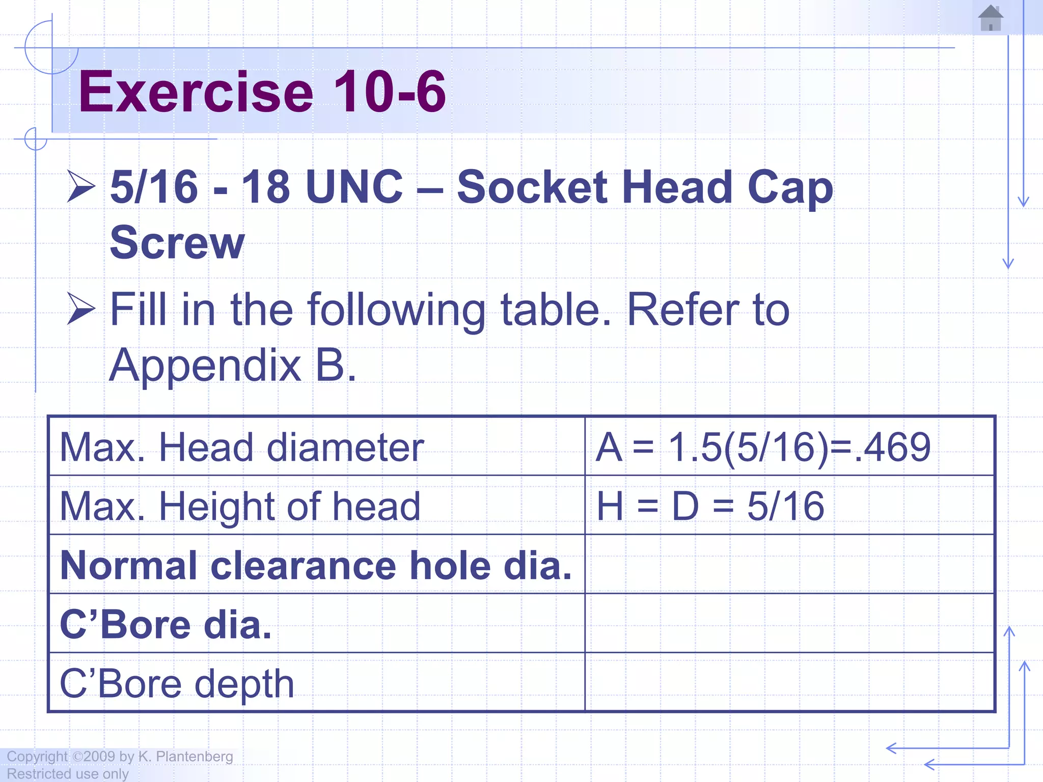
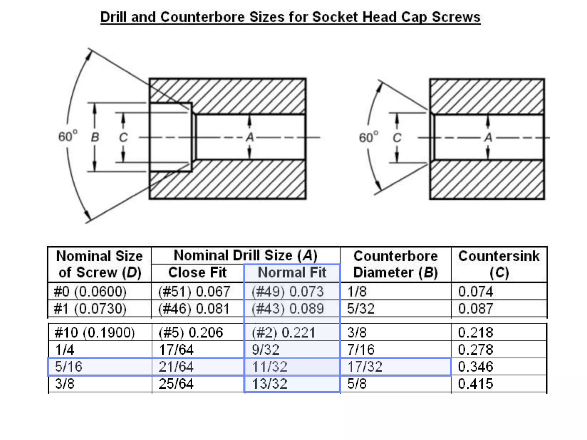
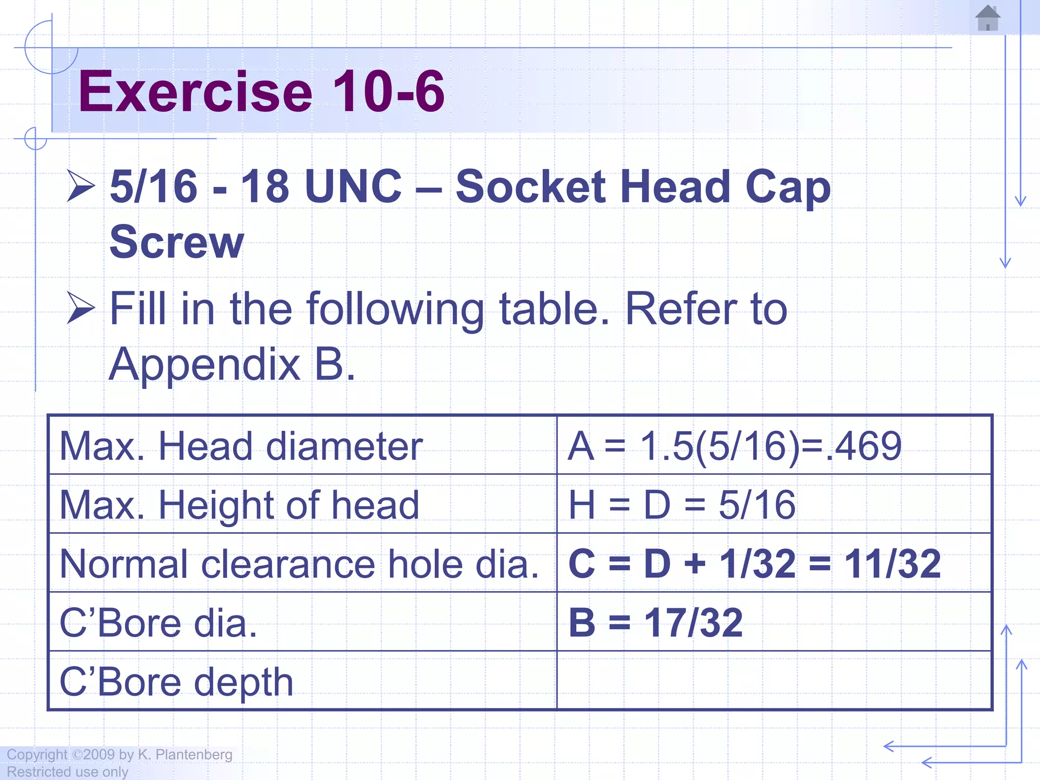
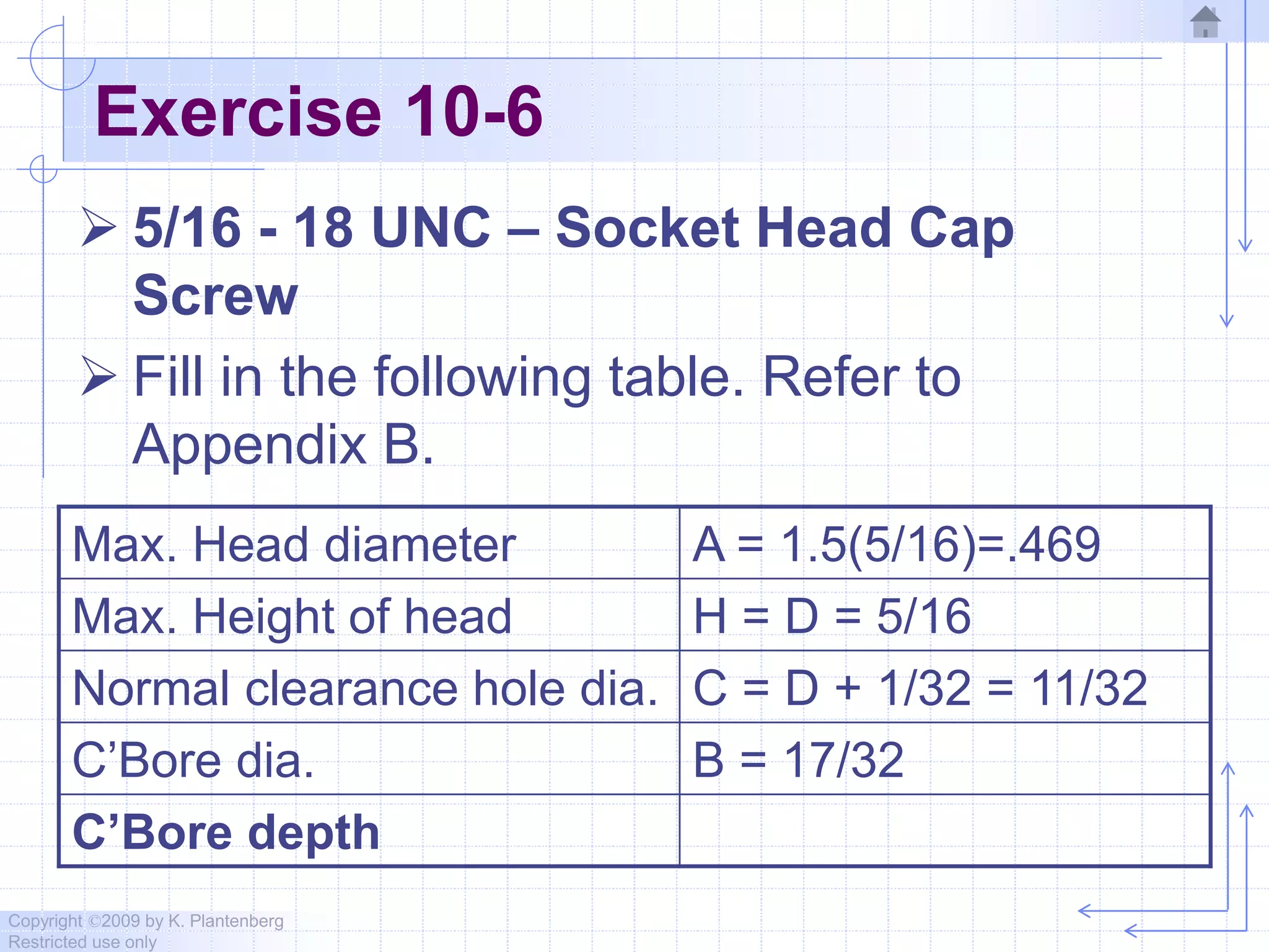

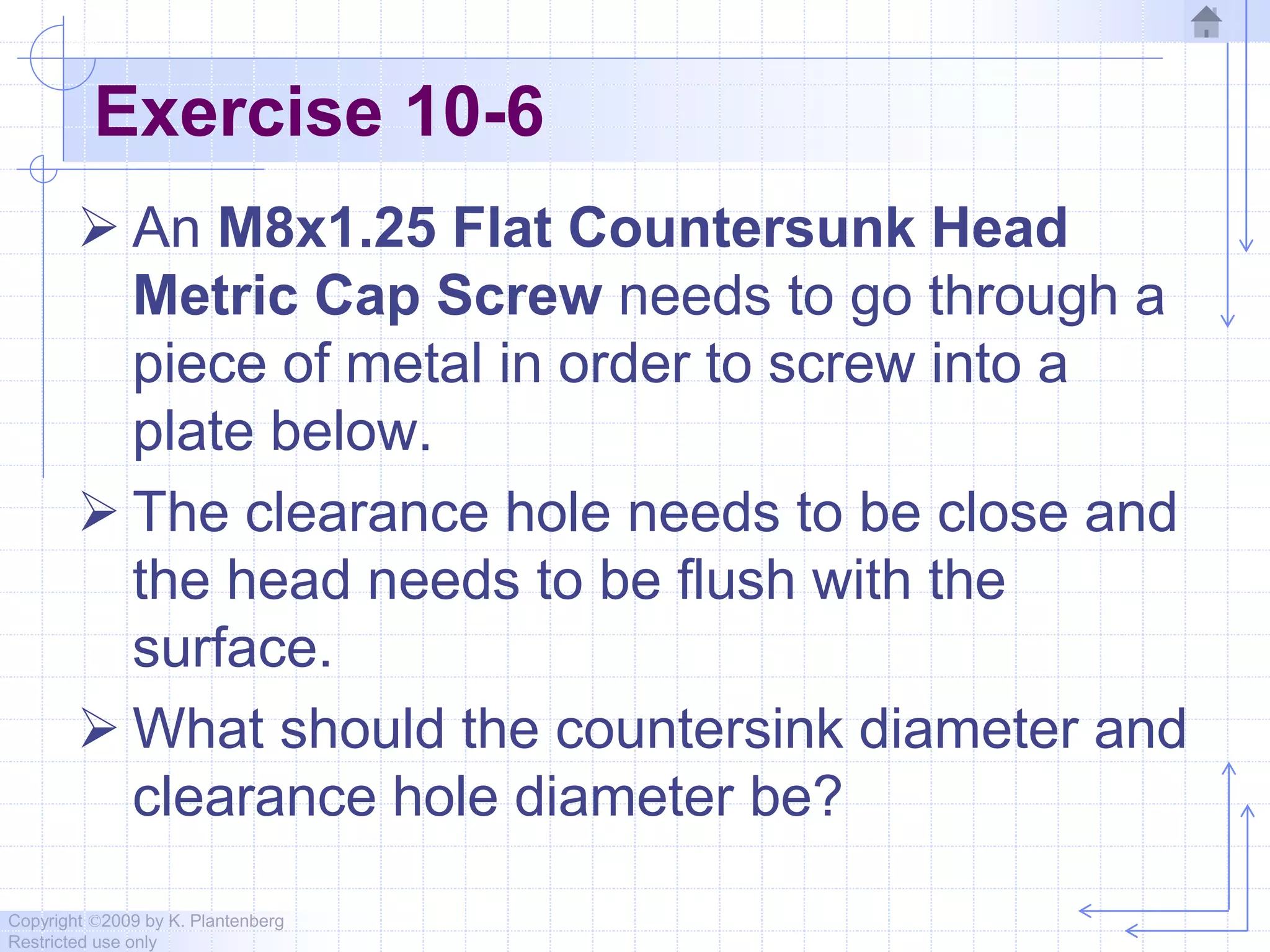
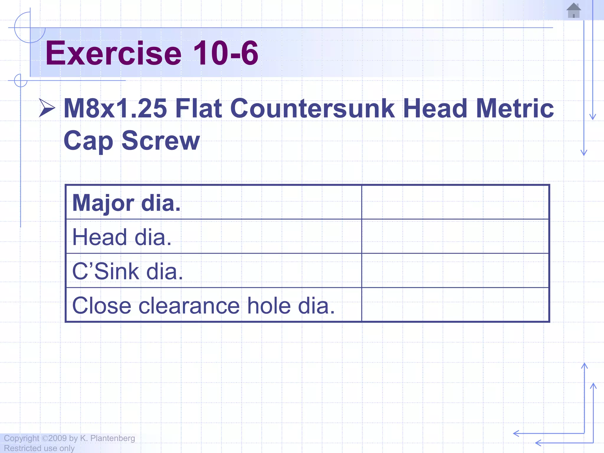
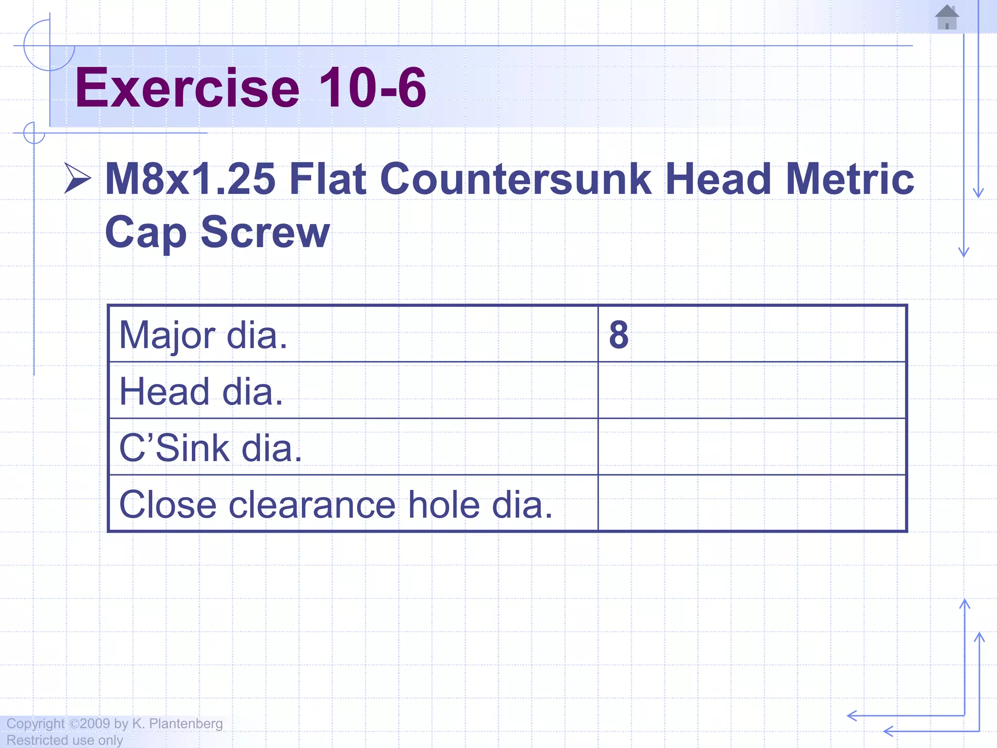
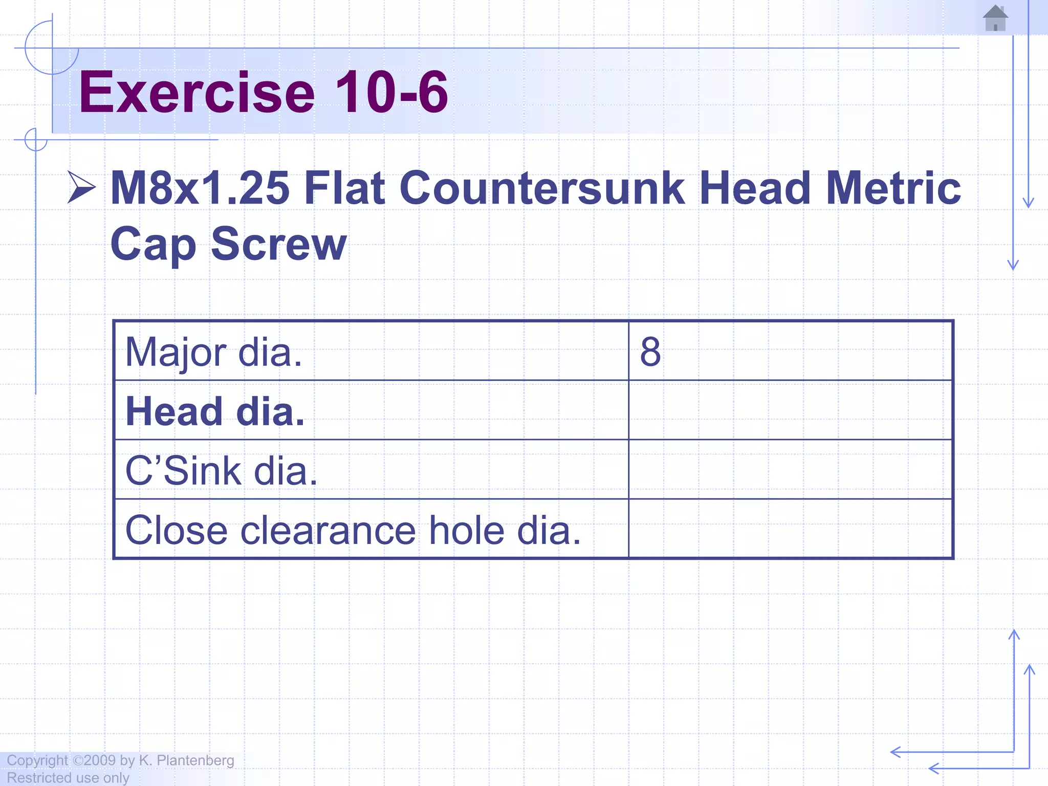
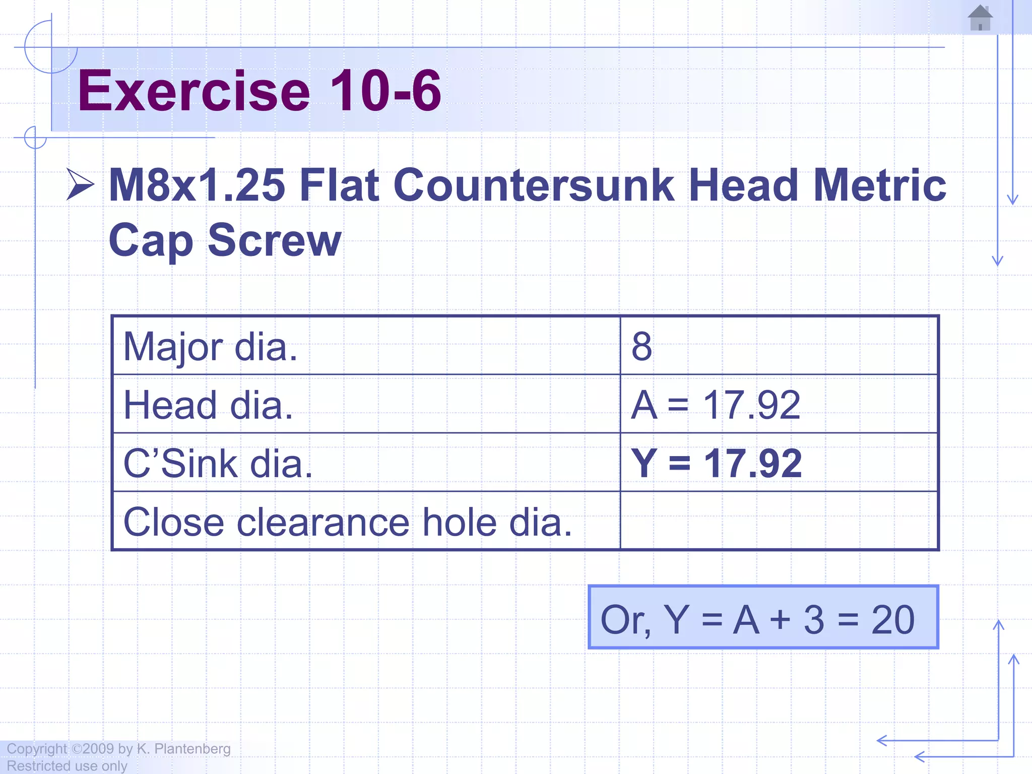
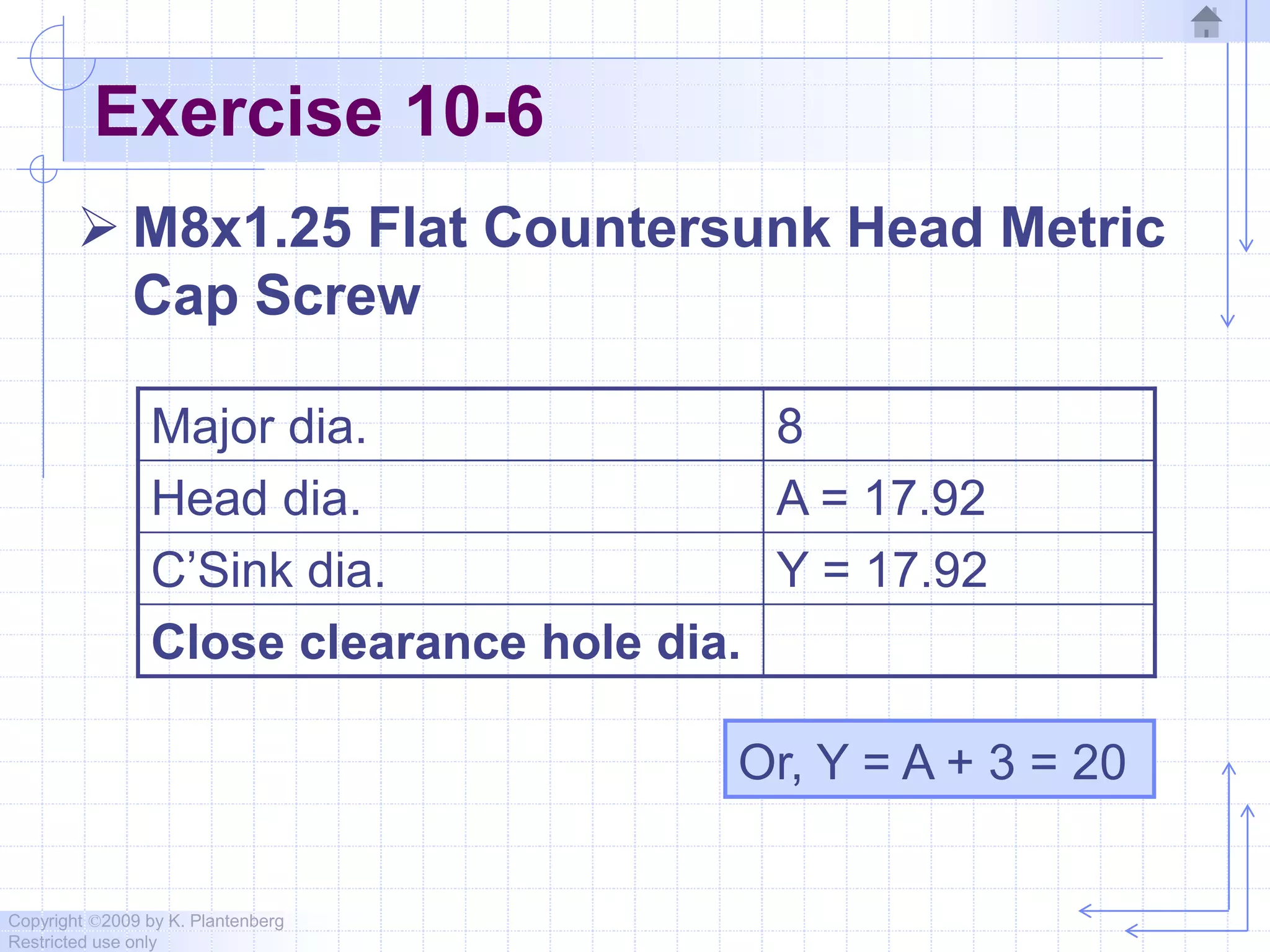
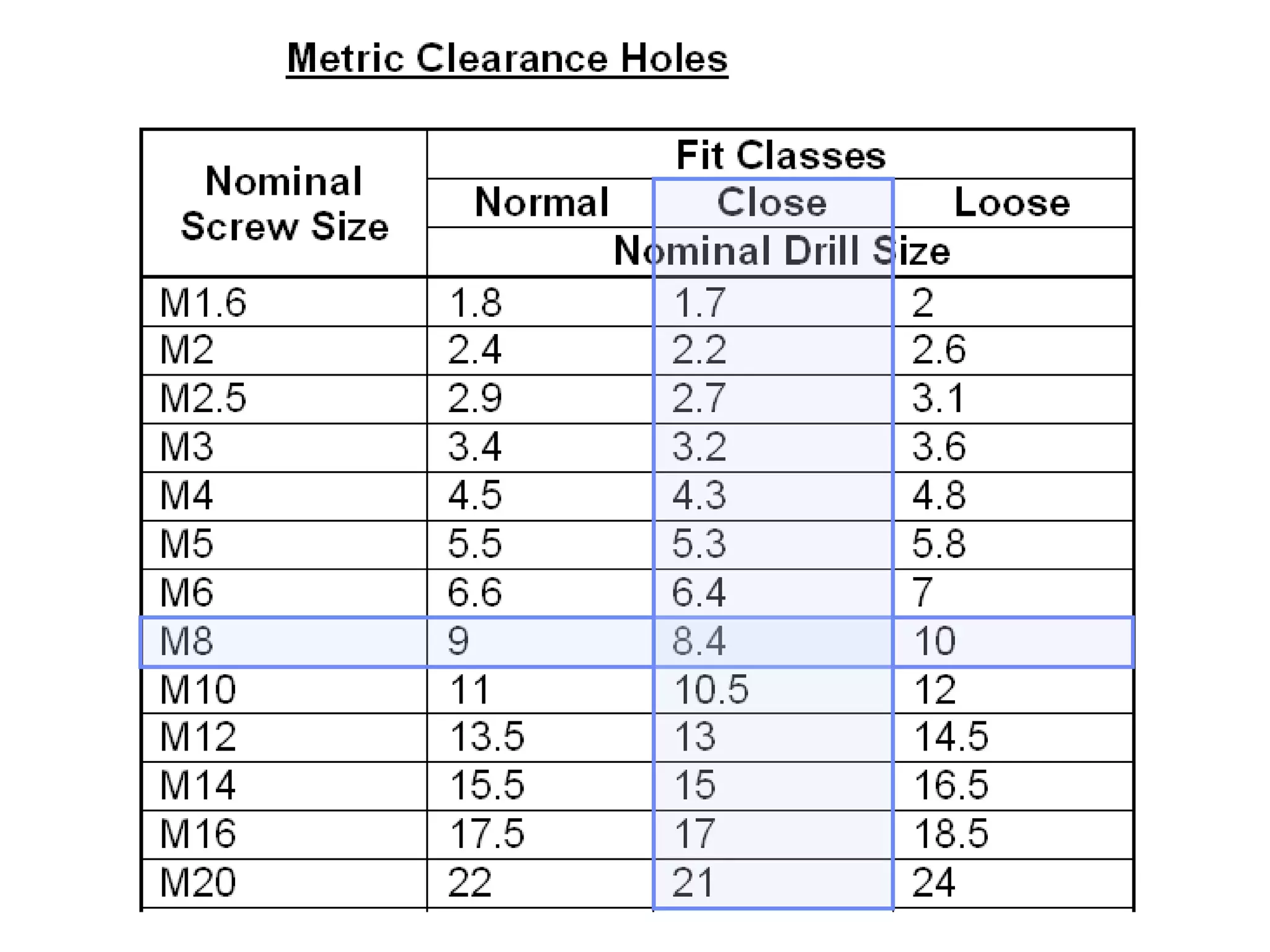
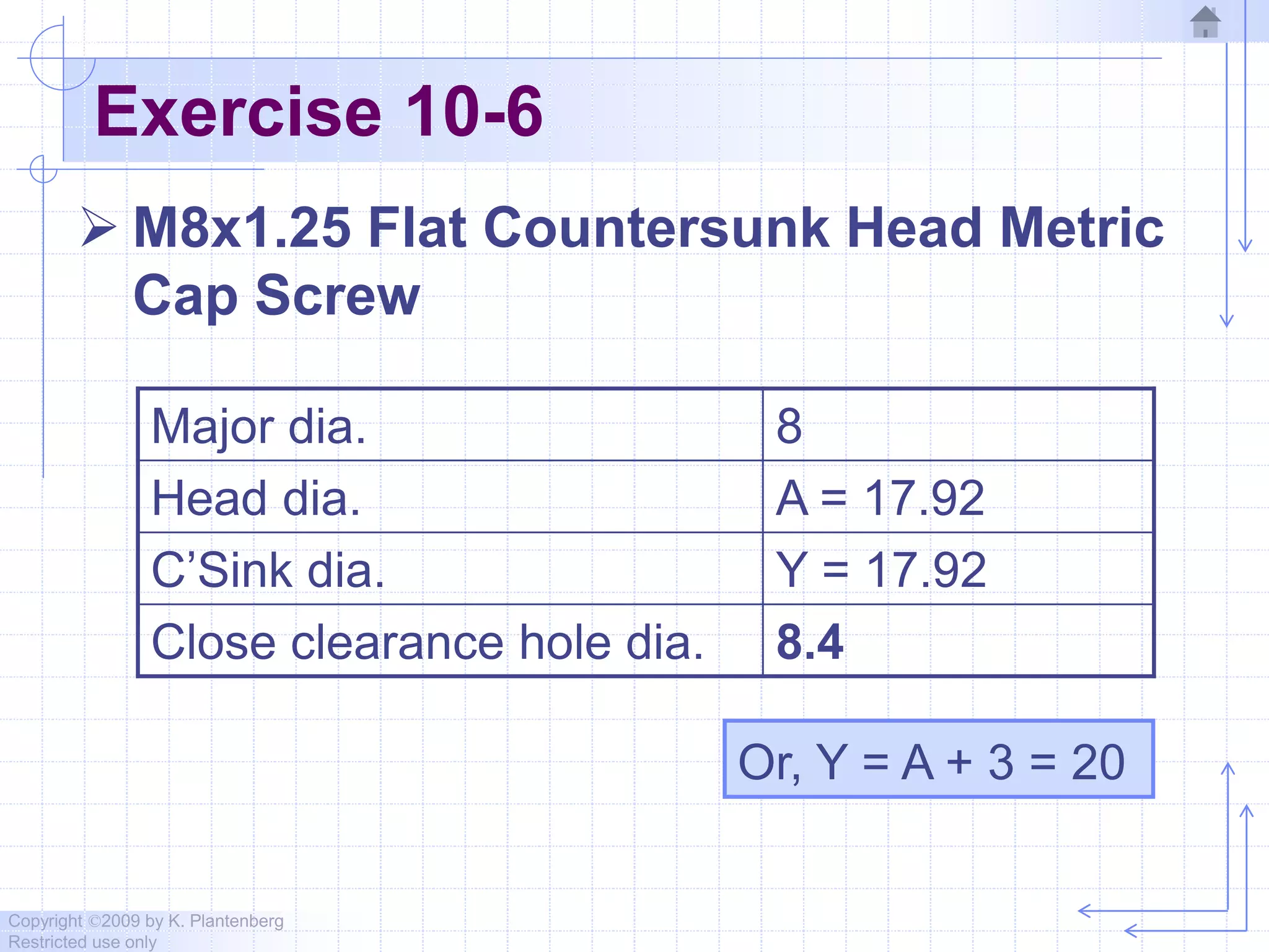


This document discusses threads and fasteners used in engineering drawings. It covers common thread types including unified and metric threads. It explains how to represent threads on drawings using detailed, schematic or simplified methods. It also describes how to include all necessary information about threads in a thread note, such as diameter, pitch, thread type and class. Key information about manufacturing and defining screw threads is provided through examples and exercises.