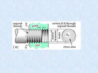
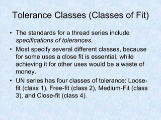
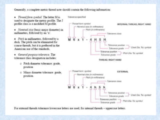
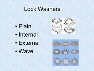
Threads and Fasteners
Engineering Graphics
Threads
• Threads are
essentially an inclined
plane wrapped
around a cylinder.
Screw Threads
• There are two distinct uses for screw threads that require
different thread characteristics:
• a power screw such as a lathe leadscrew or the screw
in a lifting jack which transforms rotary motion into linear
motion
• a threaded fastener as below which joins components
together, again by transforming rotary motion into linear
motion, though in this case the translation (linear
movement) is small. Although tightly fastened the
attachment is not permanent.
Power Screw
• Rotation of the screw is converted to linear
motion (lift)
Power Screw
• Rotation is transformed into linear motion
Threaded Fasteners
• Rotation of the screw advances the
fastener into the material
Threaded Fasteners
• The fastener and accompanying nut
fastens two or more parts together
Threaded parts were originally made by manufacturers in random
sizes to suit a particular application.
These fasteners were not interchangeable
Two Englishmen are usually credited with starting a movement toward
standards for nuts, bolts and screws. H. Mandslay, working in the machine
construction industry, tried to introduce a standard between 1800 and 1810.
The number of different sized nuts and bolts was relatively small at this
time. Mandslay influenced his apprentice J. Withworth to continue to
develop standards, and in 1841 the Withworth thread was adopted in
England as a standard in some industries.
Various industries in the US, UK, and Europe began to standardize
threaded parts to ease maintenance, interchangeability, and repair
issues. Industries manufacturing aircraft, automobiles, carriages,
railroad, munitions and household appliances all developed industry
specific standards.
.
• In the US and UK the lack of standardization
between industries became a serious problem at
the beginning of World War II, especially in the
areas of munitions, aircraft and vehicle
maintenance.
• As a result, in 1949 the Standards Committee of
the American National Standards Institute
standardized threadforms into two broad
categories, metric and unified series threads.
Unified Threaded Fasteners
• A threaded fastener is a fastening device
used to mechanically join two parts of an
assembly together( as contrasted with
welding or brazing)
• Threaded fasteners are now standardized to
allow interchangeability
• To specify a thread using the Unified
system, you must provide five pieces of
information:
• Thread form
• Thread series
• Major Diameter
• Class of fit
• Threads per inch
.
• So, for example, in the United States one
might ask for a “2-inch quarter-twenty
bolt,” which would be:
 2 inches long,
 have a nominal diameter of a quarter of an inch,
and
 have twenty threads to the inch.
• A typical smaller fastener could be “a 1-inch 8-
32,” “8” being a gauge number and “32” the
number of threads per inch.
The Fastener Description: Details
• A machine screw or its larger cousin, a bolt, is described by
length, the type of head and the thread type
• In the United States, the convention for describing threads is to
give the number of threads per inch, preceded by a gauge
number if the bolt is smaller than a quarter-inch in diameter,
otherwise by the diameter in fractions of an inch.
Machine Screw Bolt and Nut
Threadforms
• Coarse Thread Series, UNC: The coarse
thread series UNC is the most commonly
used thread system used in the majority of
screws, bolts, and nuts for quick assembly or
disassembly
• Fine Thread Series, UNF: This is used for
applications that require a higher tensile
strength than the coarse thread series and
where a thin wall is required.
• Extra Fine Series, UNEF: where length of
engagement is short and extra strength is
required.
Future threads
It might be thought that after 150 years so seemingly
simple a thing as the bolt could have been brought to
perfection, but that is not the case.
All the thread forms discussed so far share one
characteristic: they are symmetrical. But when a bolt is
tightened, the forces on the two sides of the thread are
different. That alone suggests that an asymmetrical
thread form might be better, and so it seems.
The space shuttle, for example, uses bolts with an
asymmetric thread form. In time all threaded fasteners
may have forms subtly different from those we use
today.
An Asymmetrical Threadform
Thread Specifications
• A bolt's diameter isn't all you need to know to buy a
nut to fit it. A bolt a quarter-inch in diameter might
have 20, 28 or even 32 threads per inch, and a nut
that fit one would not fit another.
• The relationship between diameter and number of
threads per inch is standardized in a number of
series, the most common in the United States being
UNC and UNF. A more complete sizing of a quarter-
inch bolt's thread might be ¼-20 UNC or ¼-28 UNF.
A few examples:
• UNC UNF
• ¼-20 ¼-28
• 5⁄16-18 5⁄16-24
Thread Terminology
• .
• The major diameter of a thread is the
diameter of the imaginary co-axial
cylinder that just touches the crest of
an external thread or the root of an
internal thread.
• The minor diameter is the diameter of
the cylinder that just touches the root
of an internal thread
• The crest of a thread is the prominent
part of the thread
• The root is the bottom of the groove
between the two flanking surfaces
• The flanks of a thread are the straight
sides that connect the crest and the
root.
• The angle of a thread is the angle
between the flanks,
• The pitch of a thread is the distance,
measured parallel to its axis, between
corresponding points on adjacent
surfaces
Thread Pitch
• Distance from crest of
one thread to the
crest of the adjacent
thread
• Used to determine
threads per inch.
Metric Thread Pitch
• Metric thread pitch
is indicated by the
distance from one
thread to the next
thread.
• 8 X 1.25 = 8mm
diameter with
1.25mm distance
between threads.
Measuring Thread Pitch
• Use Thread Pitch Gauge
Typical “UN” Series Designation
1/2” - 13 UNC - 2A
external thread
(A =external- B =internal)
Class of fit
(1 is loosest tolerance, 3 is tightest)
Pitch (threads/inch)
Nominal Diameter
(also shown as decimal - or screw gage # if less than ¼”)
Thread form
Thread series (e.g. coarse or fine)
.
• The basic profile of ISO Metric threads is built up from
contiguous equiangular triangles of height h disposed
symmetrically about a pitch line which becomes
the pitch cylinder of diameter d2 when the profile is
rotated about the axis to form the thread. The distance
between adjacent triangles - the pitch - is p = 2 h /√3.
The tips of the triangles are truncated by h/8 to form the
major diameter ( size ) d of the thread, and the bases
are truncated by h/4 to form the minor diameter d1 . It
follows that d1 = d - 5 h/4 = d - 1.08 p. This leads
to the rule of thumb for suitable tapping size drills in
normal materials : dtapping = d - p.
.
• The 60o thread form is not suitable for power screws
which transform motion and which therefore must have
high efficiency. The 'square' thread offers the best
efficiency but is generally impractical. The 'Acme' thread
form offers the best compromise between efficiency,
ease of manufacture, assembly and wear take-up using
split nuts. The stress area of Acme threads is based
upon the average of the minor and mean diameters :
• ds = d - 3/4 p .
The American thread series, with their
symbols:
• Historically Used (obsolete)
• NC American National Coarse
• NF American National Fine Thread
• NEF American National Extra Fine Thread
• 8N American National 8 Pitch
• 12N American National 12 Pitch
• 16N American National 16 Pitch
• NS Special Threads of American National Form
• SB Manufacturers Stove Bolt Standard Thread
• Commonly Used
• UNC Unified Coarse Thread
• UNF Unified Fine Thread
• UNS Unified threads of special diameters, pitches, and length of
engagement
• UNM Unified Miniature
Specialized application threads
• A knuckle thread is
used to manufacture
threaded container
caps and frequently
has multiple lead
threads (discussed
below).
Multiple Lead Threads
• Fasteners can be made
with two or three parallel
threads instead of the
usual one, although no
standard series includes
such a thread.
• The advantage of such
threading is that the bolt
will be stronger than a
single thread bolt whose
nut would advance the
same distance in one turn
Lead and Start
• When a nut on a screw
is rotated by one turn,
it travels along the
screw a distance
known as the lead L.
• Power screws may
employ multiple
threads, or starts,
so L = p ∗ number of
starts as illustrated.
• Fasteners on the other
hand are almost
invariably single start (
L = p ).
Tolerance Classes (Classes of Fit)
• The standards for a thread series include
specifications of tolerances.
• Most specify several different classes, because
for some uses a close fit is essential, while
achieving it for other uses would be a waste of
money.
• UN series has four classes of tolerance: Loose-
fit (class 1), Free-fit (class 2), Medium-Fit (class
3), and Close-fit (class 4).
Handedness
• Almost all threaded
fasteners tighten when
the head or nut is rotated
clockwise. That is, as a
viewer turns a nut
clockwise it moves away
from them. Such a
fastener is said to have a
right-hand thread; all
screw fasteners are
assumed to be right-hand
unless otherwise
specified.
• Left-hand threads are
usually found only on
rotating machinery,
turnbuckles, and as a
safety feature on welding
equipment.
“Right hand Rule” for threads
• Threaded fasteners are typicallly “right
handed” to avoid confusion in
tightening
• LH screws appear in turnbuckles and
in certain bicycle parts where the
prevailing torque would tend to loosen
RH fasteners.
.
• Precession can cause fastenings under large torque loads to
unscrew themselves.
• Automobile lug nuts
• Automobiles have also used left-threaded lug nuts on left-side
wheels, but now commonly use tapered lug nuts.
Bicycle pedals
• Bicycle pedals are left-threaded on the left-hand crank so that
precession tightens the pedal rather than loosening it.
• Safety Issues
• In industrial application where similar-looking connections must be
made, in parts and hose connections. LH and RH threading
prevents incorrect attachments.
• Turnbuckles
• Two threaded hoops connected to a shackle can be drawn together
if LH and RH threads are used at each end
Types of Fasteners
• There are a variety of fasteners
manufactured to meet the need of
designers in different applications
• Following are the most common:
Thread Types
• Machine screws
• Wood screws
• Tapping screws
Bolt Grades
• Grade indicates the tensile
strength of the bolt
• Determined by bolt material
and heat treating
Bolthead Symbols
• Bolt heads are maked with information
about the bolt:
– Strength
– Manufacturing process
– Manufacturer
– Material composition
SAE Bolt Designations
SAE
Grade
No.
Size
range
Tensile
strength,
ksi Material Head marking
1
2
1/4 thru 1-1/2
1/4 thru 3/4
7/8 thru 1-1/2
60
74
60
Low or medium
carbon steel
5 1/4 thru 1
1-1/8 thru 1-1/2
120
105
Medium carbon steel,
quenched & tempered
5.2 1/4 thru 1 120 Low carbon
martensite steel,
quenched & tempered
7 1/4 thru 1-1/2 133 Medium carbon
alloy steel,
quenched & tempered
8 1/4 thru 1-1/2 150 Medium carbon
alloy steel,
quenched & tempered
8.2 1/4 thru 1 150 Low carbon
martensite steel,
quenched & tempered
• A typical hexagon headed
bolt and nut are shown.
• The diameter of the bolt
shank is usually the same
as the outside diameter -
the major diameter or
briefly size - of the
thread. The radiused fillet
at the junction of shank
and head reduces stress
concentration
Drawing Threads
• Threads are typically drawn in one of three forms:
• Detailed
• Simplified
• Schematic
Drilled and Tapped Holes
• You specify tapped (threaded) holes by a note giving the
diameter of the tap drill (21/64"); depth of hole (1 3/8”);
thread information (½” diameter, Unified National Course
threads, Class 2); and length of thread (1"), as:
21/64 DRILL x 1 3/8 DEEP
1/2-13 UNC - 2 x 1 DEEP
Thread Notes
Hole and Thread Formation
• .
Tightening Torque
It is typical on engines for bolts to have a
specified tightening torque.
• It results in a quantified preload on the bolts
• Insures that parts never separate
• Maintains friction (no sliding to shear forces)
• Insures even distribution of loading
– prevent warpage of mating parts
– uniform pressure distribution over seal or
gasket
• Prevents bolt from loosening
• Reduces fatique effects
Bolt Manufacturing Processes
• Forging (upsetting)
• Rolling
Thread-rolling processes: a) reciprocating flat dies; and b) two-roller dies.
Threaded fasteners, such as bolts, are made economically by these
processes at high rates of production
a) b)
Manufacturing Processes -
continued
• Turning on screw machines
(a) Differences in the diameters of machined and rolled threads. (b) Grain flow in machined
and rolled threads. Unlike machining, which cuts through the grains of the metal, rolled threads
have improved strength because of cold working and favorable grain flow.
Schematic
2.
1.
End
View
Detailed
Representing External Threads
• Options for representing external
threads in a drawing
Representing Internal Threads
• Options for representing internal threads
Schematic
(in section)
Detailed
(in section)
Simplified End View
SAE Bolt Grades
• Grade refers to strength
• Count lines +2 to get grade
• Higher the number – the stronger the
bolt
Metric bolt property class
• Property Class numbers
• 1st # - tensile strength
• 2nd # - yield strength
SAE Bolt Grades
• Grade refers to strength
• The stronger the bolt the
higher the grade
Metric bolt property class
• Property Class numbers
• 1st # - tensile strength
• 2nd # - yield strength
Machine screws
• Bolts that are less than ¼
“
• Use numbers to identify
them instead of fractions
• Sized from 0 – 12
• Also used threads per
inch
• Example of 6-32
• 6=size 32=threads per
inch
Sheet metal screws
• Self tapping
• Use a punch
to make a
hole for them
• Don’t confuse
them with
wood screws
Nuts
• Standard = hex, wing,
speed nuts
• Locknuts = collar, slotted,
crimped (do NOT re-use)
• Castle and Pal-nuts –
used with cotter pins.
Nut Diameter
Non-Threaded Fasteners
• Rivets
• Pins
• Keys
• Retaining rings
• Locking washers
• Lock screws
Lock Washers
• Plain
• Internal
• External
• Wave
Lock Nuts
A stud has no head and is threaded at both ends.
The ends are not necessarily the same.
clearance hole through a component, typically
15-20% larger than the bolt/stud size to facilitate
assembly and to clear any shank/ head fillet;
tapped hole which is drilled smaller than the root
or minor diameter of the fastener
Retaining Rings
• Used in U-joints, etc.
Retaining Ring Pliers
• Both internal and external
models available
• Used to remove rings
Cotter pins
• Used on castle &
slotted nuts
• Used on linkages
• Do NOT replace with
nails or anything else
Internal Hair Pin Cotters
• Used like cotter pins
Keys
• Used to keep two
items stationary to
each other by the use
of slots
• Crankshaft to
dampener
Roll Pins
• Pins are a unique
type of fastener that
can hold two
materials together
non-permanently.
Unlike bolts and nuts,
which press the
materials together for
holding power, pins
can hold the
assembly together
with no torque
pressure.
Set Screws
• Used to hold a part in
position only.
• Usually has an Allen
head
Standard Set Screws
Rivets
• Used in door panels,
window motors, and
upper ball joints
Nut-serts
• Used in body
applications

Fasteners.pdf

  • 1.
  • 2.
    Threads • Threads are essentiallyan inclined plane wrapped around a cylinder.
  • 3.
    Screw Threads • Thereare two distinct uses for screw threads that require different thread characteristics: • a power screw such as a lathe leadscrew or the screw in a lifting jack which transforms rotary motion into linear motion • a threaded fastener as below which joins components together, again by transforming rotary motion into linear motion, though in this case the translation (linear movement) is small. Although tightly fastened the attachment is not permanent.
  • 4.
    Power Screw • Rotationof the screw is converted to linear motion (lift)
  • 5.
    Power Screw • Rotationis transformed into linear motion
  • 7.
    Threaded Fasteners • Rotationof the screw advances the fastener into the material
  • 8.
    Threaded Fasteners • Thefastener and accompanying nut fastens two or more parts together
  • 9.
    Threaded parts wereoriginally made by manufacturers in random sizes to suit a particular application. These fasteners were not interchangeable Two Englishmen are usually credited with starting a movement toward standards for nuts, bolts and screws. H. Mandslay, working in the machine construction industry, tried to introduce a standard between 1800 and 1810. The number of different sized nuts and bolts was relatively small at this time. Mandslay influenced his apprentice J. Withworth to continue to develop standards, and in 1841 the Withworth thread was adopted in England as a standard in some industries. Various industries in the US, UK, and Europe began to standardize threaded parts to ease maintenance, interchangeability, and repair issues. Industries manufacturing aircraft, automobiles, carriages, railroad, munitions and household appliances all developed industry specific standards.
  • 10.
    . • In theUS and UK the lack of standardization between industries became a serious problem at the beginning of World War II, especially in the areas of munitions, aircraft and vehicle maintenance. • As a result, in 1949 the Standards Committee of the American National Standards Institute standardized threadforms into two broad categories, metric and unified series threads.
  • 11.
    Unified Threaded Fasteners •A threaded fastener is a fastening device used to mechanically join two parts of an assembly together( as contrasted with welding or brazing) • Threaded fasteners are now standardized to allow interchangeability • To specify a thread using the Unified system, you must provide five pieces of information: • Thread form • Thread series • Major Diameter • Class of fit • Threads per inch
  • 12.
    . • So, forexample, in the United States one might ask for a “2-inch quarter-twenty bolt,” which would be:  2 inches long,  have a nominal diameter of a quarter of an inch, and  have twenty threads to the inch. • A typical smaller fastener could be “a 1-inch 8- 32,” “8” being a gauge number and “32” the number of threads per inch.
  • 13.
    The Fastener Description:Details • A machine screw or its larger cousin, a bolt, is described by length, the type of head and the thread type • In the United States, the convention for describing threads is to give the number of threads per inch, preceded by a gauge number if the bolt is smaller than a quarter-inch in diameter, otherwise by the diameter in fractions of an inch. Machine Screw Bolt and Nut
  • 16.
    Threadforms • Coarse ThreadSeries, UNC: The coarse thread series UNC is the most commonly used thread system used in the majority of screws, bolts, and nuts for quick assembly or disassembly • Fine Thread Series, UNF: This is used for applications that require a higher tensile strength than the coarse thread series and where a thin wall is required. • Extra Fine Series, UNEF: where length of engagement is short and extra strength is required.
  • 17.
    Future threads It mightbe thought that after 150 years so seemingly simple a thing as the bolt could have been brought to perfection, but that is not the case. All the thread forms discussed so far share one characteristic: they are symmetrical. But when a bolt is tightened, the forces on the two sides of the thread are different. That alone suggests that an asymmetrical thread form might be better, and so it seems. The space shuttle, for example, uses bolts with an asymmetric thread form. In time all threaded fasteners may have forms subtly different from those we use today.
  • 18.
  • 19.
    Thread Specifications • Abolt's diameter isn't all you need to know to buy a nut to fit it. A bolt a quarter-inch in diameter might have 20, 28 or even 32 threads per inch, and a nut that fit one would not fit another. • The relationship between diameter and number of threads per inch is standardized in a number of series, the most common in the United States being UNC and UNF. A more complete sizing of a quarter- inch bolt's thread might be ¼-20 UNC or ¼-28 UNF. A few examples: • UNC UNF • ¼-20 ¼-28 • 5⁄16-18 5⁄16-24
  • 20.
    Thread Terminology • . •The major diameter of a thread is the diameter of the imaginary co-axial cylinder that just touches the crest of an external thread or the root of an internal thread. • The minor diameter is the diameter of the cylinder that just touches the root of an internal thread • The crest of a thread is the prominent part of the thread • The root is the bottom of the groove between the two flanking surfaces • The flanks of a thread are the straight sides that connect the crest and the root. • The angle of a thread is the angle between the flanks, • The pitch of a thread is the distance, measured parallel to its axis, between corresponding points on adjacent surfaces
  • 21.
    Thread Pitch • Distancefrom crest of one thread to the crest of the adjacent thread • Used to determine threads per inch.
  • 22.
    Metric Thread Pitch •Metric thread pitch is indicated by the distance from one thread to the next thread. • 8 X 1.25 = 8mm diameter with 1.25mm distance between threads.
  • 23.
    Measuring Thread Pitch •Use Thread Pitch Gauge
  • 28.
    Typical “UN” SeriesDesignation 1/2” - 13 UNC - 2A external thread (A =external- B =internal) Class of fit (1 is loosest tolerance, 3 is tightest) Pitch (threads/inch) Nominal Diameter (also shown as decimal - or screw gage # if less than ¼”) Thread form Thread series (e.g. coarse or fine)
  • 32.
    . • The basicprofile of ISO Metric threads is built up from contiguous equiangular triangles of height h disposed symmetrically about a pitch line which becomes the pitch cylinder of diameter d2 when the profile is rotated about the axis to form the thread. The distance between adjacent triangles - the pitch - is p = 2 h /√3. The tips of the triangles are truncated by h/8 to form the major diameter ( size ) d of the thread, and the bases are truncated by h/4 to form the minor diameter d1 . It follows that d1 = d - 5 h/4 = d - 1.08 p. This leads to the rule of thumb for suitable tapping size drills in normal materials : dtapping = d - p.
  • 33.
    . • The 60othread form is not suitable for power screws which transform motion and which therefore must have high efficiency. The 'square' thread offers the best efficiency but is generally impractical. The 'Acme' thread form offers the best compromise between efficiency, ease of manufacture, assembly and wear take-up using split nuts. The stress area of Acme threads is based upon the average of the minor and mean diameters : • ds = d - 3/4 p .
  • 34.
    The American threadseries, with their symbols: • Historically Used (obsolete) • NC American National Coarse • NF American National Fine Thread • NEF American National Extra Fine Thread • 8N American National 8 Pitch • 12N American National 12 Pitch • 16N American National 16 Pitch • NS Special Threads of American National Form • SB Manufacturers Stove Bolt Standard Thread • Commonly Used • UNC Unified Coarse Thread • UNF Unified Fine Thread • UNS Unified threads of special diameters, pitches, and length of engagement • UNM Unified Miniature
  • 35.
    Specialized application threads •A knuckle thread is used to manufacture threaded container caps and frequently has multiple lead threads (discussed below).
  • 36.
    Multiple Lead Threads •Fasteners can be made with two or three parallel threads instead of the usual one, although no standard series includes such a thread. • The advantage of such threading is that the bolt will be stronger than a single thread bolt whose nut would advance the same distance in one turn
  • 37.
    Lead and Start •When a nut on a screw is rotated by one turn, it travels along the screw a distance known as the lead L. • Power screws may employ multiple threads, or starts, so L = p ∗ number of starts as illustrated. • Fasteners on the other hand are almost invariably single start ( L = p ).
  • 38.
    Tolerance Classes (Classesof Fit) • The standards for a thread series include specifications of tolerances. • Most specify several different classes, because for some uses a close fit is essential, while achieving it for other uses would be a waste of money. • UN series has four classes of tolerance: Loose- fit (class 1), Free-fit (class 2), Medium-Fit (class 3), and Close-fit (class 4).
  • 39.
    Handedness • Almost allthreaded fasteners tighten when the head or nut is rotated clockwise. That is, as a viewer turns a nut clockwise it moves away from them. Such a fastener is said to have a right-hand thread; all screw fasteners are assumed to be right-hand unless otherwise specified. • Left-hand threads are usually found only on rotating machinery, turnbuckles, and as a safety feature on welding equipment. “Right hand Rule” for threads
  • 40.
    • Threaded fastenersare typicallly “right handed” to avoid confusion in tightening • LH screws appear in turnbuckles and in certain bicycle parts where the prevailing torque would tend to loosen RH fasteners.
  • 41.
    . • Precession cancause fastenings under large torque loads to unscrew themselves. • Automobile lug nuts • Automobiles have also used left-threaded lug nuts on left-side wheels, but now commonly use tapered lug nuts. Bicycle pedals • Bicycle pedals are left-threaded on the left-hand crank so that precession tightens the pedal rather than loosening it. • Safety Issues • In industrial application where similar-looking connections must be made, in parts and hose connections. LH and RH threading prevents incorrect attachments. • Turnbuckles • Two threaded hoops connected to a shackle can be drawn together if LH and RH threads are used at each end
  • 42.
    Types of Fasteners •There are a variety of fasteners manufactured to meet the need of designers in different applications • Following are the most common:
  • 43.
    Thread Types • Machinescrews • Wood screws • Tapping screws
  • 45.
    Bolt Grades • Gradeindicates the tensile strength of the bolt • Determined by bolt material and heat treating
  • 48.
    Bolthead Symbols • Boltheads are maked with information about the bolt: – Strength – Manufacturing process – Manufacturer – Material composition
  • 50.
    SAE Bolt Designations SAE Grade No. Size range Tensile strength, ksiMaterial Head marking 1 2 1/4 thru 1-1/2 1/4 thru 3/4 7/8 thru 1-1/2 60 74 60 Low or medium carbon steel 5 1/4 thru 1 1-1/8 thru 1-1/2 120 105 Medium carbon steel, quenched & tempered 5.2 1/4 thru 1 120 Low carbon martensite steel, quenched & tempered 7 1/4 thru 1-1/2 133 Medium carbon alloy steel, quenched & tempered 8 1/4 thru 1-1/2 150 Medium carbon alloy steel, quenched & tempered 8.2 1/4 thru 1 150 Low carbon martensite steel, quenched & tempered
  • 51.
    • A typicalhexagon headed bolt and nut are shown. • The diameter of the bolt shank is usually the same as the outside diameter - the major diameter or briefly size - of the thread. The radiused fillet at the junction of shank and head reduces stress concentration
  • 52.
    Drawing Threads • Threadsare typically drawn in one of three forms: • Detailed • Simplified • Schematic
  • 53.
    Drilled and TappedHoles • You specify tapped (threaded) holes by a note giving the diameter of the tap drill (21/64"); depth of hole (1 3/8”); thread information (½” diameter, Unified National Course threads, Class 2); and length of thread (1"), as: 21/64 DRILL x 1 3/8 DEEP 1/2-13 UNC - 2 x 1 DEEP
  • 54.
  • 59.
    Hole and ThreadFormation • .
  • 61.
    Tightening Torque It istypical on engines for bolts to have a specified tightening torque. • It results in a quantified preload on the bolts • Insures that parts never separate • Maintains friction (no sliding to shear forces) • Insures even distribution of loading – prevent warpage of mating parts – uniform pressure distribution over seal or gasket • Prevents bolt from loosening • Reduces fatique effects
  • 62.
    Bolt Manufacturing Processes •Forging (upsetting) • Rolling Thread-rolling processes: a) reciprocating flat dies; and b) two-roller dies. Threaded fasteners, such as bolts, are made economically by these processes at high rates of production a) b)
  • 63.
    Manufacturing Processes - continued •Turning on screw machines (a) Differences in the diameters of machined and rolled threads. (b) Grain flow in machined and rolled threads. Unlike machining, which cuts through the grains of the metal, rolled threads have improved strength because of cold working and favorable grain flow.
  • 64.
    Schematic 2. 1. End View Detailed Representing External Threads •Options for representing external threads in a drawing
  • 65.
    Representing Internal Threads •Options for representing internal threads Schematic (in section) Detailed (in section) Simplified End View
  • 66.
    SAE Bolt Grades •Grade refers to strength • Count lines +2 to get grade • Higher the number – the stronger the bolt
  • 67.
    Metric bolt propertyclass • Property Class numbers • 1st # - tensile strength • 2nd # - yield strength
  • 68.
    SAE Bolt Grades •Grade refers to strength • The stronger the bolt the higher the grade
  • 69.
    Metric bolt propertyclass • Property Class numbers • 1st # - tensile strength • 2nd # - yield strength
  • 70.
    Machine screws • Boltsthat are less than ¼ “ • Use numbers to identify them instead of fractions • Sized from 0 – 12 • Also used threads per inch • Example of 6-32 • 6=size 32=threads per inch
  • 71.
    Sheet metal screws •Self tapping • Use a punch to make a hole for them • Don’t confuse them with wood screws
  • 72.
    Nuts • Standard =hex, wing, speed nuts • Locknuts = collar, slotted, crimped (do NOT re-use) • Castle and Pal-nuts – used with cotter pins.
  • 73.
  • 74.
    Non-Threaded Fasteners • Rivets •Pins • Keys • Retaining rings • Locking washers • Lock screws
  • 75.
    Lock Washers • Plain •Internal • External • Wave
  • 76.
  • 77.
    A stud hasno head and is threaded at both ends. The ends are not necessarily the same. clearance hole through a component, typically 15-20% larger than the bolt/stud size to facilitate assembly and to clear any shank/ head fillet; tapped hole which is drilled smaller than the root or minor diameter of the fastener
  • 78.
    Retaining Rings • Usedin U-joints, etc.
  • 79.
    Retaining Ring Pliers •Both internal and external models available • Used to remove rings
  • 81.
    Cotter pins • Usedon castle & slotted nuts • Used on linkages • Do NOT replace with nails or anything else
  • 82.
    Internal Hair PinCotters • Used like cotter pins
  • 83.
    Keys • Used tokeep two items stationary to each other by the use of slots • Crankshaft to dampener
  • 84.
    Roll Pins • Pinsare a unique type of fastener that can hold two materials together non-permanently. Unlike bolts and nuts, which press the materials together for holding power, pins can hold the assembly together with no torque pressure.
  • 85.
    Set Screws • Usedto hold a part in position only. • Usually has an Allen head
  • 86.
  • 87.
    Rivets • Used indoor panels, window motors, and upper ball joints
  • 89.
    Nut-serts • Used inbody applications