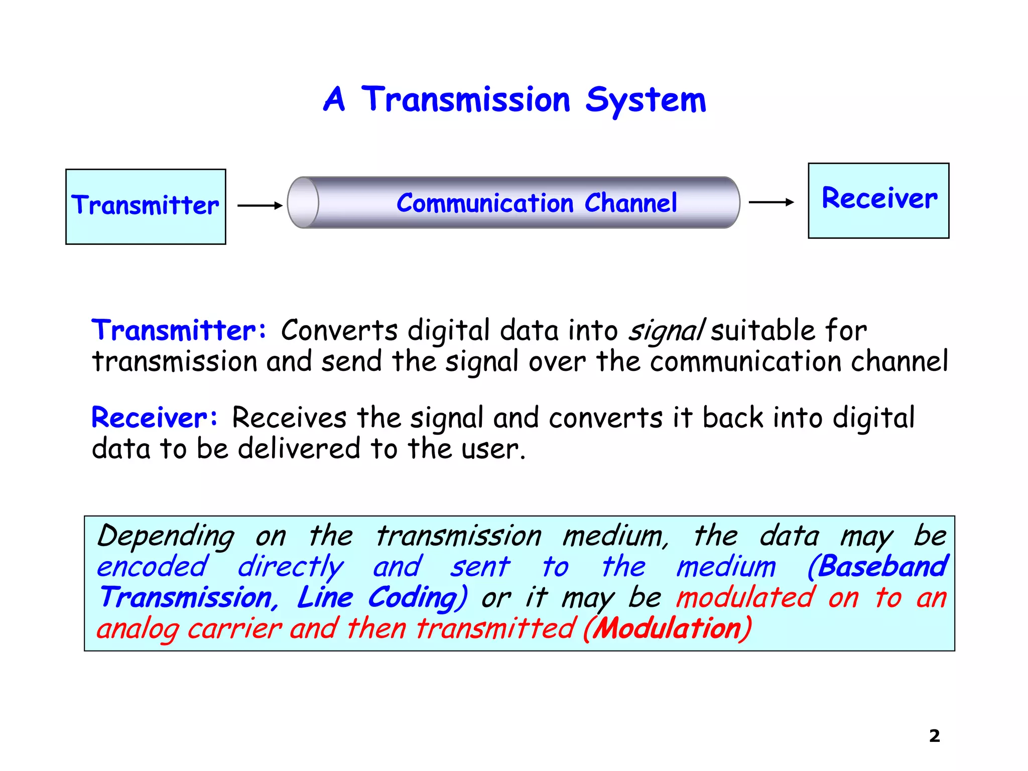
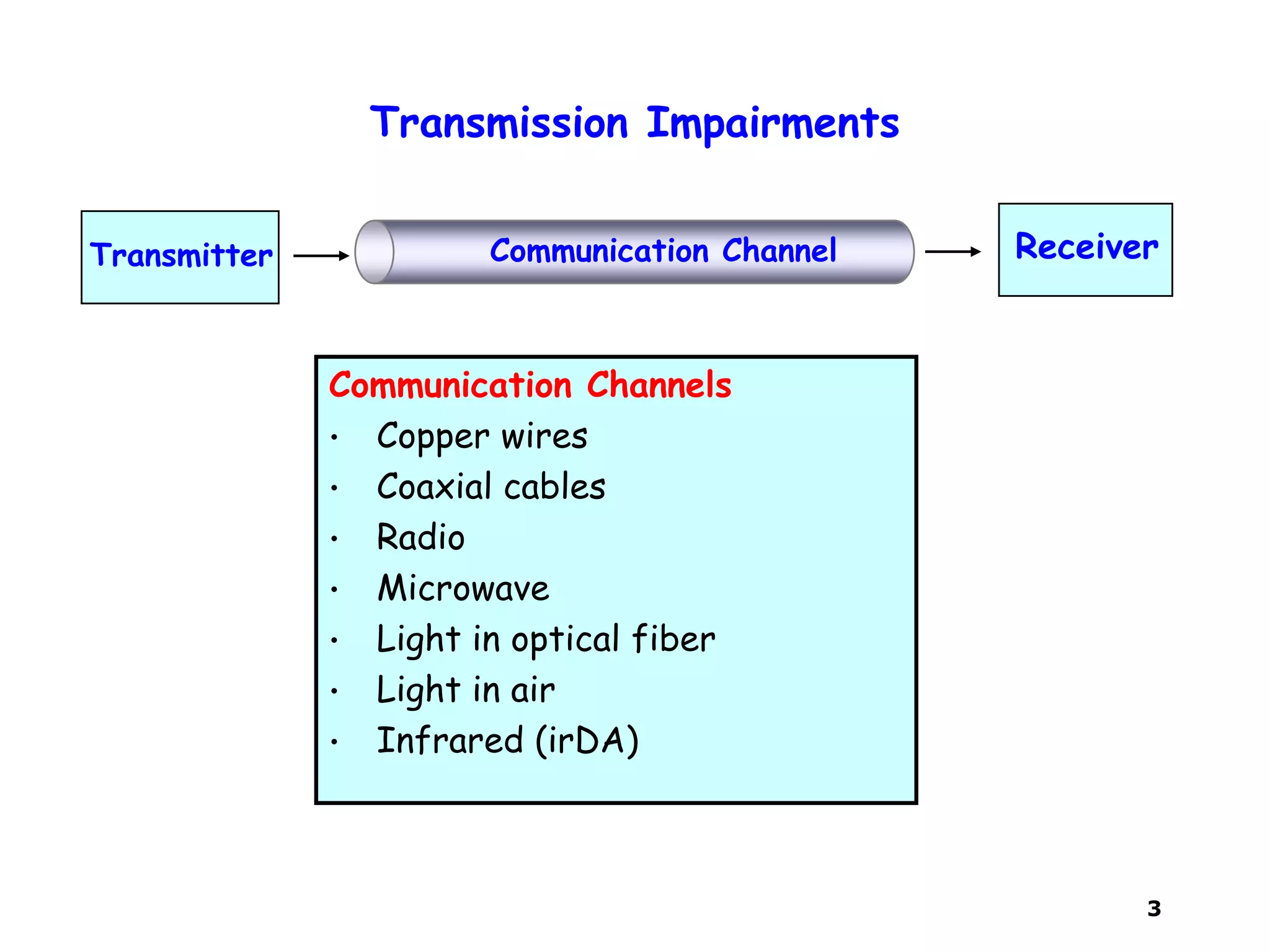
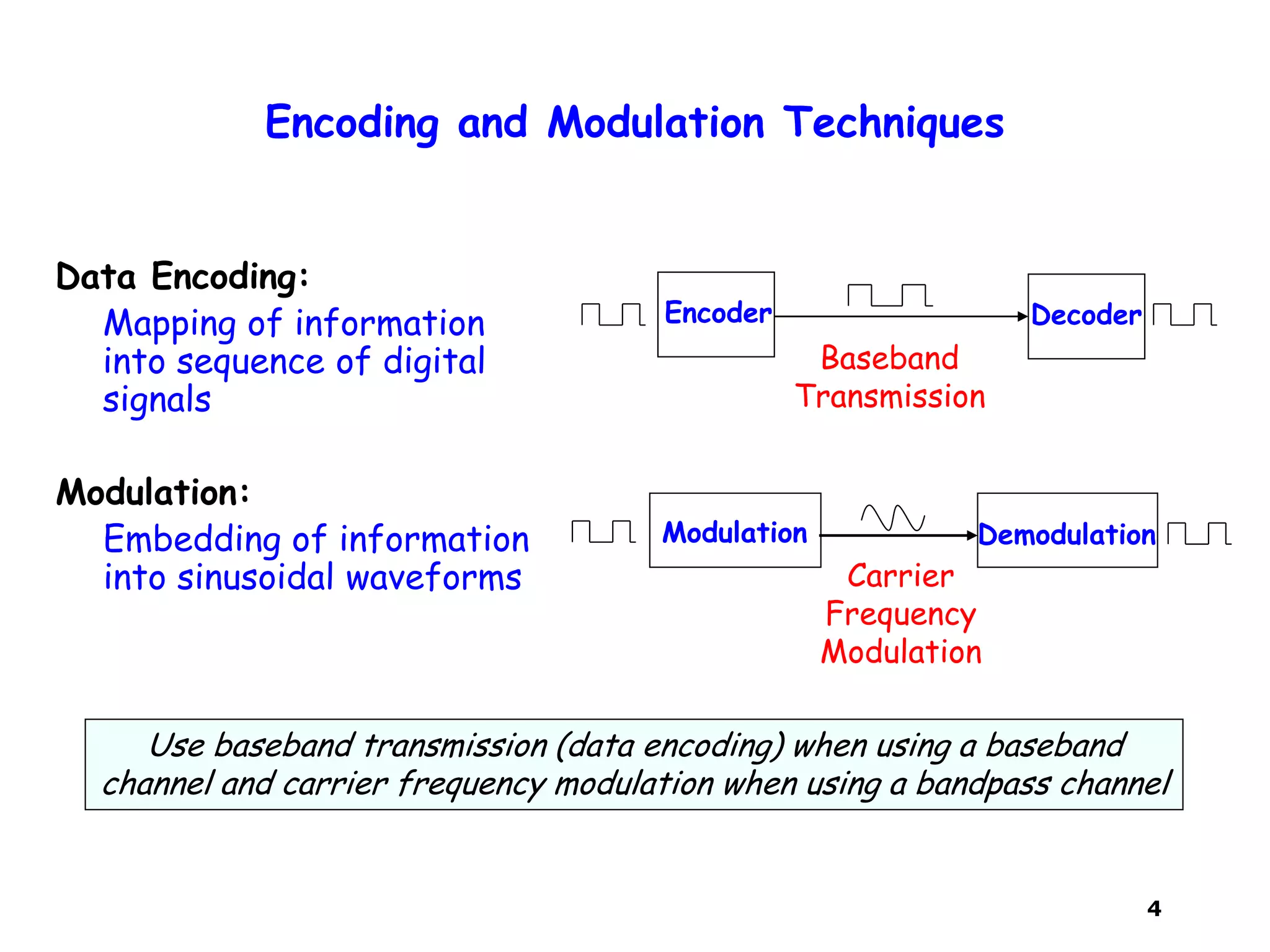
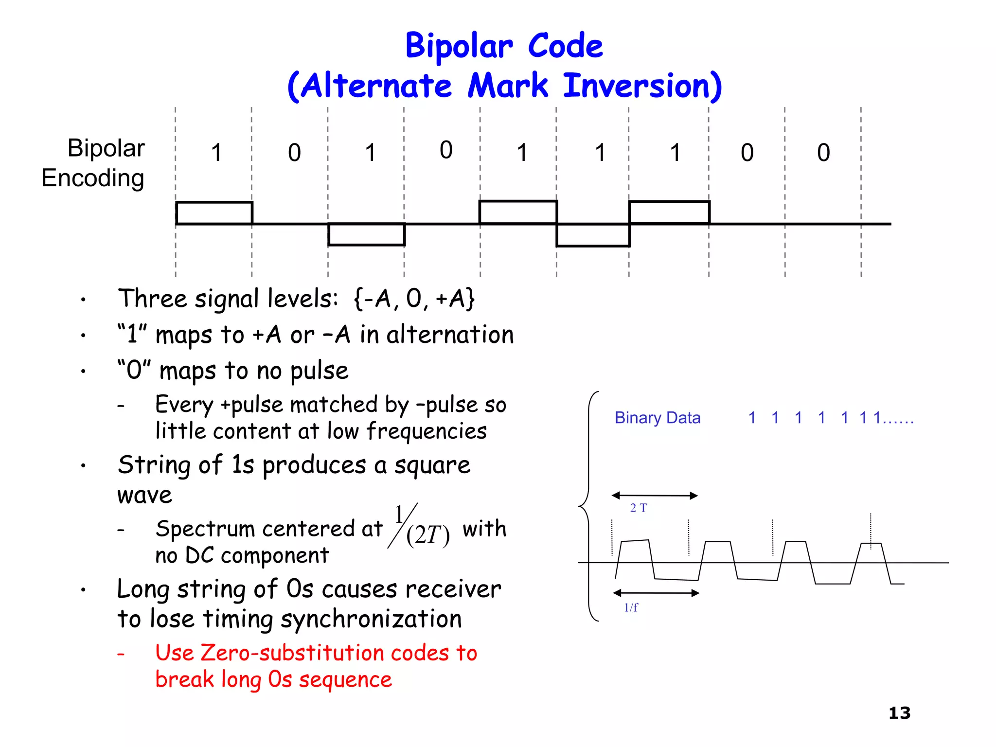
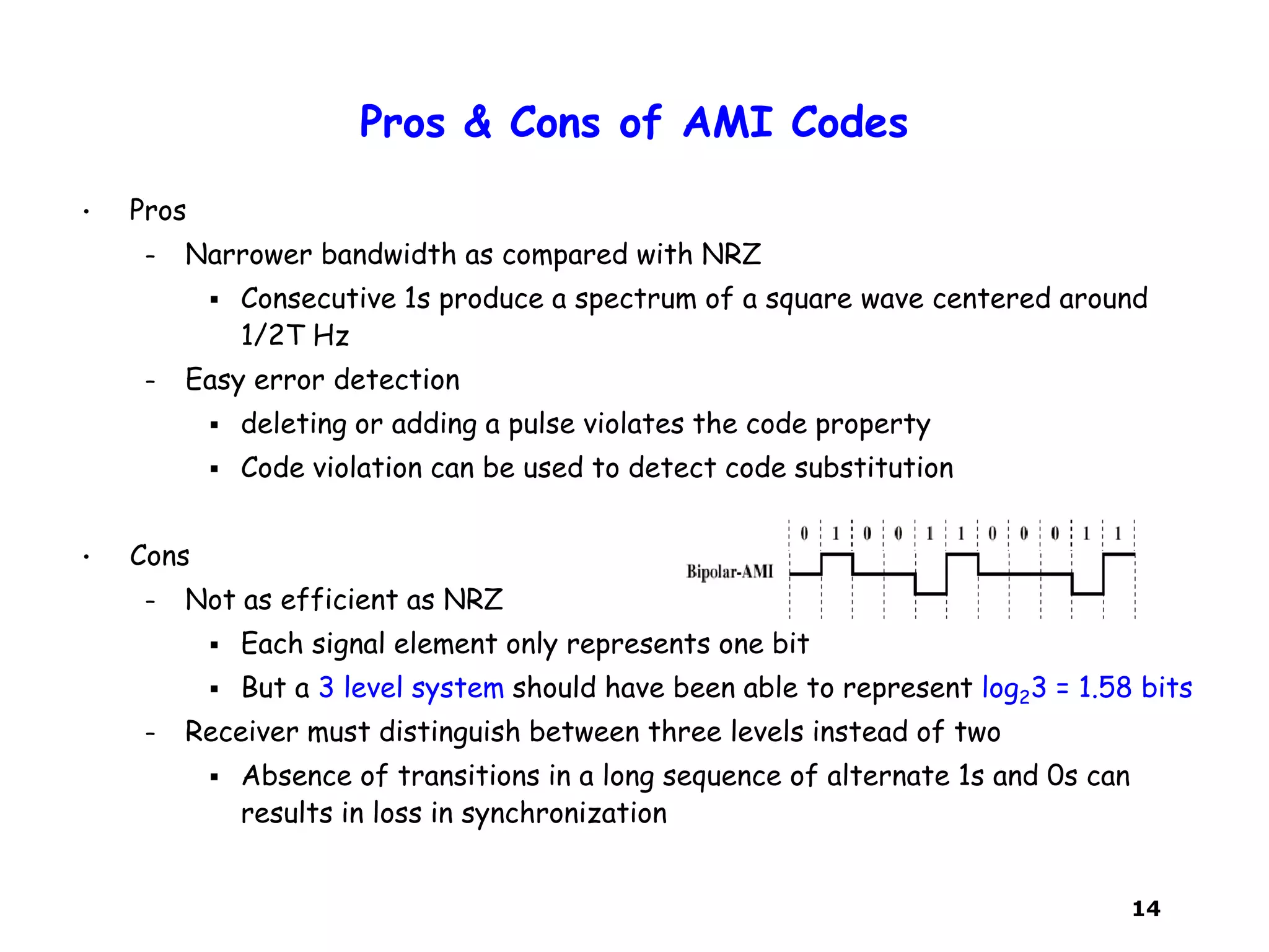
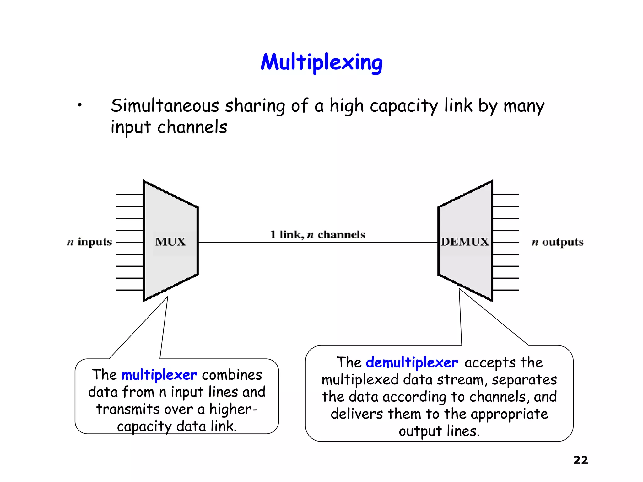
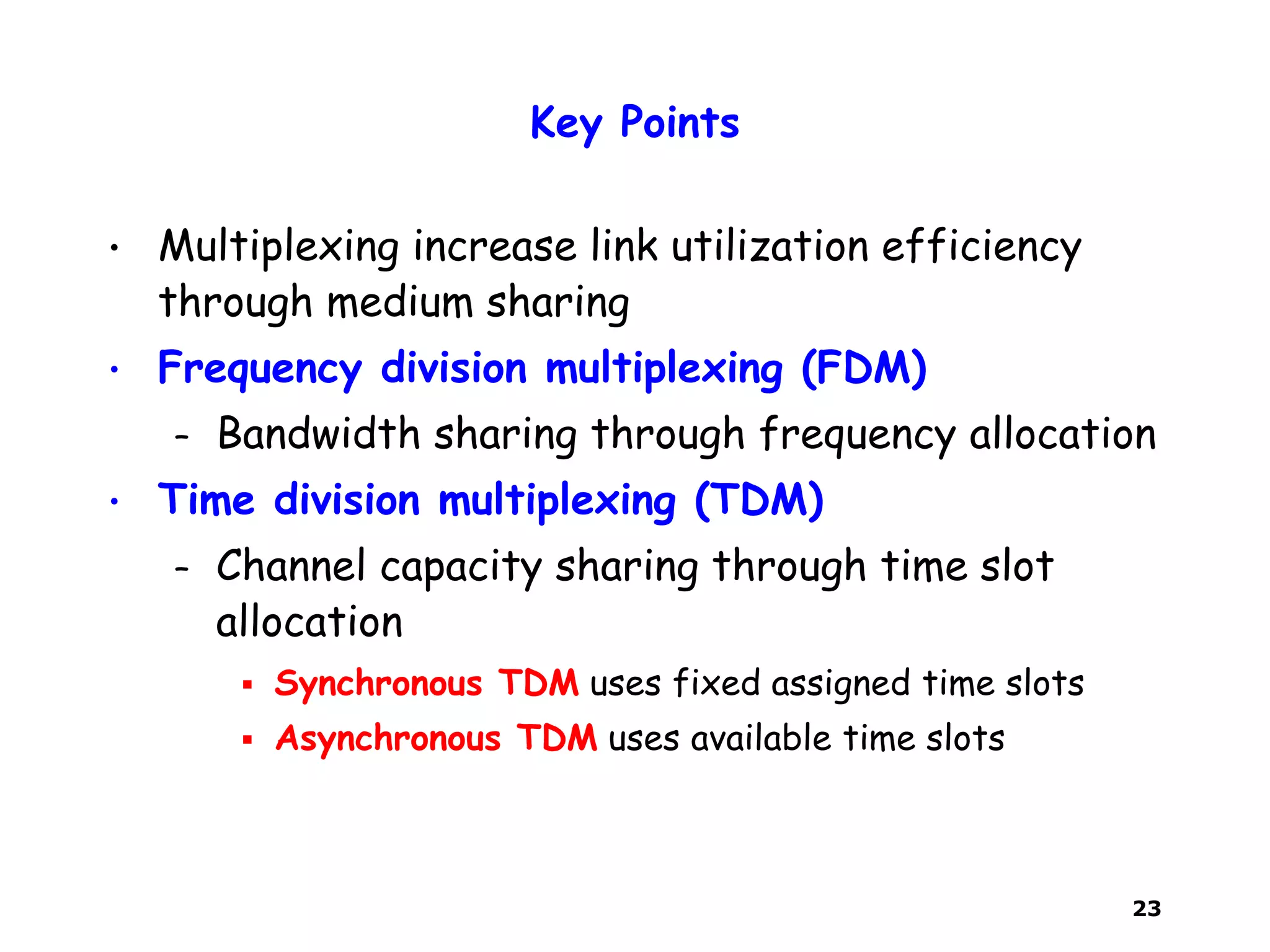
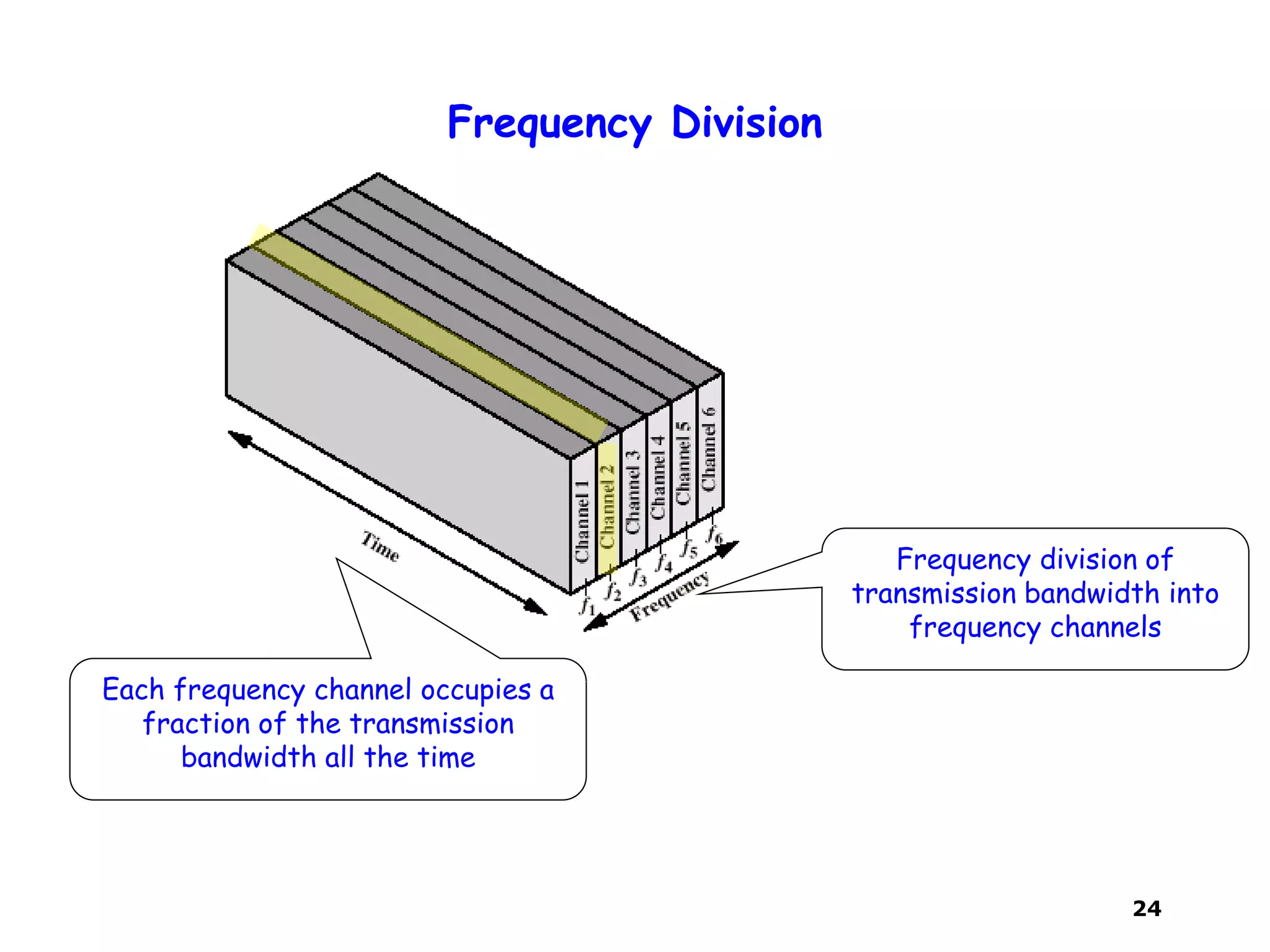
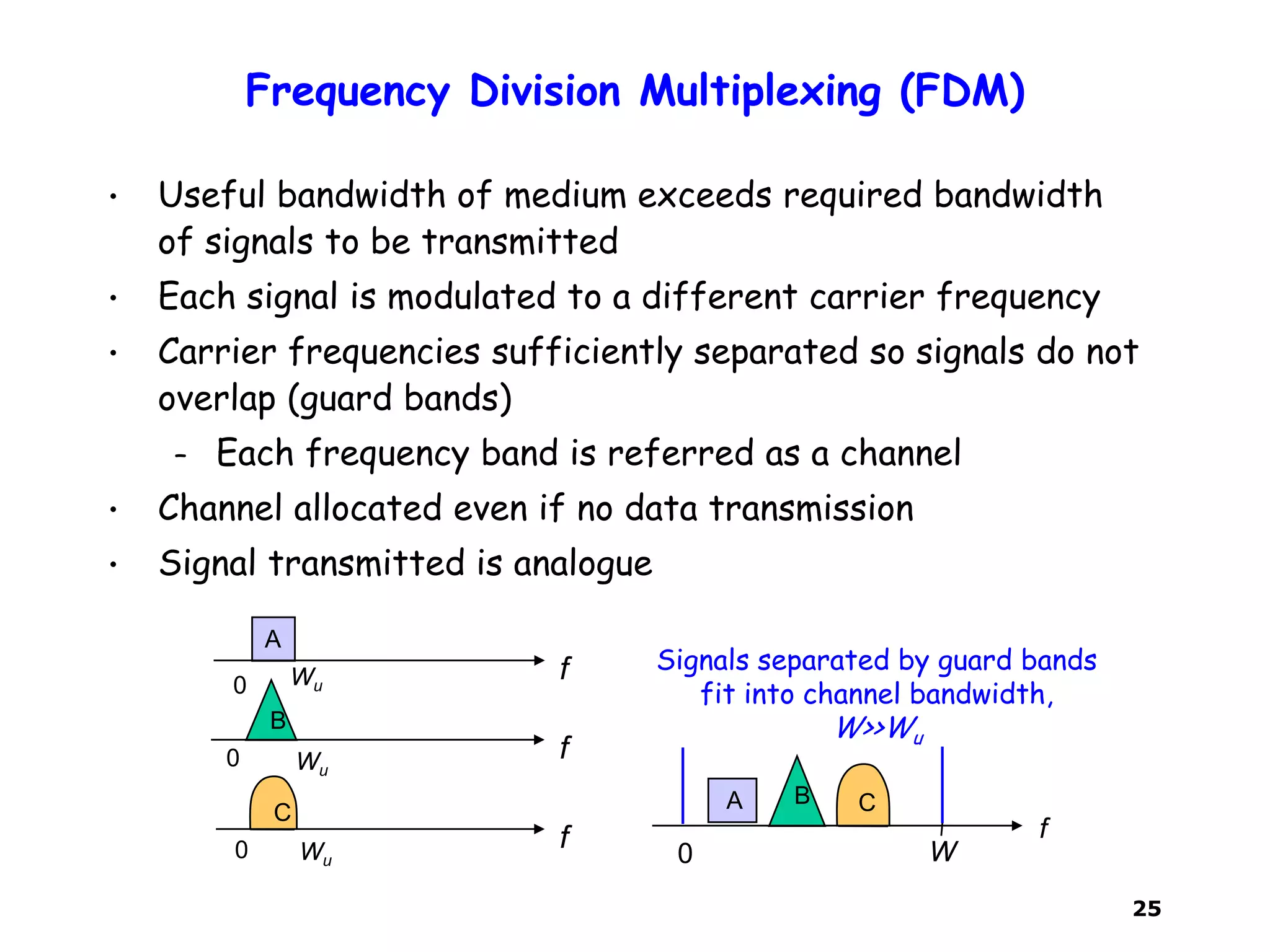
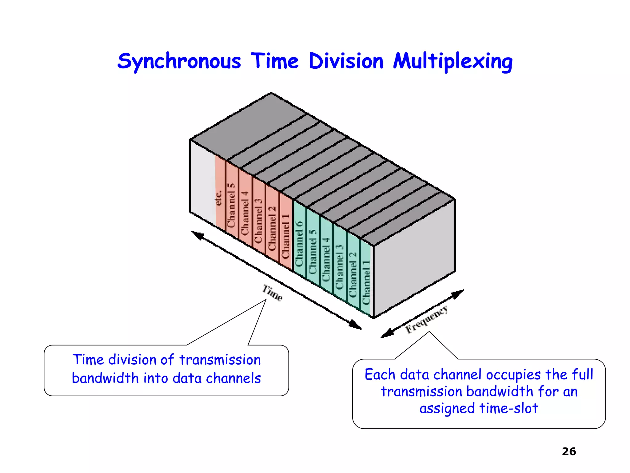
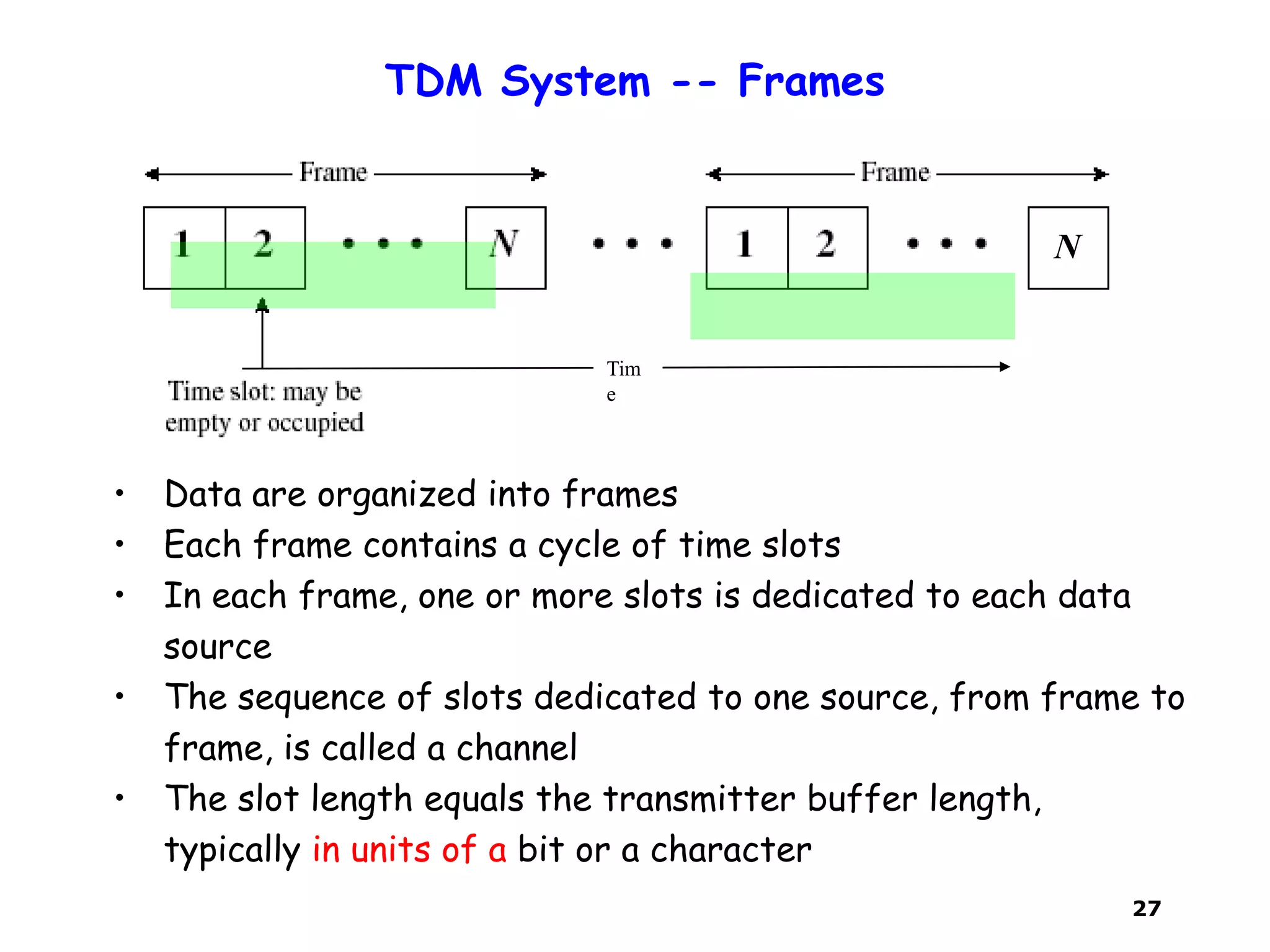
Communication Networks
Sanjay K. Bose
Lecture Set II
Data Communications for Networks
2
A Transmission System
Transmitter: Converts digital data into signal suitable for
transmission and send the signal over the communication channel
Receiver: Receives the signal and converts it back into digital
data to be delivered to the user.
ReceiverCommunication ChannelTransmitter
Depending on the transmission medium, the data may be
encoded directly and sent to the medium (Baseband
Transmission, Line Coding) or it may be modulated on to an
analog carrier and then transmitted (Modulation)
3
Transmission Impairments
Communication Channels
• Copper wires
• Coaxial cables
• Radio
• Microwave
• Light in optical fiber
• Light in air
• Infrared (irDA)
ReceiverCommunication ChannelTransmitter
4
Encoding and Modulation Techniques
Data Encoding:
Mapping of information
into sequence of digital
signals
Modulation:
Embedding of information
into sinusoidal waveforms
Modulation Demodulation
Encoder Decoder
Baseband
Transmission
Carrier
Frequency
Modulation
Use baseband transmission (data encoding) when using a baseband
channel and carrier frequency modulation when using a bandpass channel
5
Channel Bandwidth (Baseband Channel)
ChannelX(t) = a cos(2Ď€ft) Y(t) = aA(f)cos(2Ď€ft)
A(f) Frequency Characterization of the
Channel
B0
f
A(f)
Ideal Baseband channel
All frequencies in range (0, B) are
passed with same attenuation
Flat Frequency Spectrum
Frequency Spectrum is not ideally
flat
B0
f
A(f)
Real Baseband channel
6
Channel Bandwidth (Bandpass Channel)
ChannelX(t) = a cos(2Ď€ft) Y(t) = aA(f)cos(2Ď€ft)
A(f) Frequency Characterization of the
Channel
fc+½B f
A(f)
Ideal Bandpass channel
Flat Frequency Spectrum
fc - ½B fc fc+½B f
A(f)
Real Bandpass channel
Frequency Spectrum is not ideally
flat
fc - ½B
fc
7
Why Line Coding and Modulation?
– Need to find a proper digital signal to
represent the data bits (0 and 1) in
baseband transmission Line Coding
– Need to find a proper analog
representation (i.e. modulated carrier)
of data bits for bandpass transmission
Modulation
8
Design considerations in Line Coding
• Transmitted power Low power consumption desirable
• Bit timing Transitions in signal help timing recovery
• Bandwidth efficiency Excessive transitions wastes bandwidth
• Low frequency content Try to avoid signals with high DC content
ď‚§ Some channels block low frequencies (i.e. at or near DC)
 In such channels, long periods of +A or of –A causes signal to
“droop”
• Error detection Ability to detect errors helps
• Complexity/cost Low cost implementations (e.g. on a chip)
desirable
9
Some Simple Line Coding Schemes
NRZ-inverted
(differential
encoding)
1 0 1 0 1 1 0 01
Unipolar
NRZ
Bipolar
encoding
Manchester
encoding
Differential
Manchester
encoding
Polar NRZ
+ +
- -
+ + +
o o
+ + + + +
+ + +
- -
o o oo
10
Manchester Code
• “1” maps into high-to-low transition (A/2 first T/2, -A/2 last
T/2)
• “0” maps into low-to-high transition (-A/2 first T/2, A/2 last
T/2)
• Every interval has transition in middle
– Self-clocking feature
– Timing recovery easy
– Uses double the minimum bandwidth
• Simple to implement
• Used in Ethernet & other LAN standards
1 0 1 0 1 1 0 01
Manchester
Encoding
11
mB nB codes
• mB nB line code provides increased number of transitions for
improved synchronisation
• Maps block of m bits into n bits; n>m
• Manchester code is 1B2B code
• 4B 5B code used in FDDI LAN
• 8B 10B code used in Gigabit Ethernet
• 64B 66B code used in 10G Ethernet
1 0 1 0 1 1 0 01
Manchester
Encoding
(1B 2B code)
12
Differential Manchester Coding
• Differential Manchester
– Mid-bit transition is clocking only
– Transition at start of a bit period represents zero
– No transition at start of a bit period represents one
– Used by IEEE 802.5 (Token ring)
Clocking
transitions
Performance similar to Manchester Coding
13
Bipolar Code
(Alternate Mark Inversion)
• Three signal levels: {-A, 0, +A}
• “1” maps to +A or –A in alternation
• “0” maps to no pulse
– Every +pulse matched by –pulse so
little content at low frequencies
• String of 1s produces a square
wave
– Spectrum centered at with
no DC component
• Long string of 0s causes receiver
to lose timing synchronization
– Use Zero-substitution codes to
break long 0s sequence
1 0 1 0 1 1 0 01Bipolar
Encoding
Binary Data 1 1 1 1 1 1 1……
1/f
2 T
1
(2 )T
14
Pros & Cons of AMI Codes
• Pros
– Narrower bandwidth as compared with NRZ
ď‚§ Consecutive 1s produce a spectrum of a square wave centered around
1/2T Hz
– Easy error detection
ď‚§ deleting or adding a pulse violates the code property
ď‚§ Code violation can be used to detect code substitution
• Cons
– Not as efficient as NRZ
ď‚§ Each signal element only represents one bit
ď‚§ But a 3 level system should have been able to represent log23 = 1.58 bits
– Receiver must distinguish between three levels instead of two
ď‚§ Absence of transitions in a long sequence of alternate 1s and 0s can
results in loss in synchronization
15
Scramble Codes
• Use scrambling to replace sequences that would produce
constant voltage
– Bipolar With 8 Zeros Substitution (B8ZS)
– High Density Bipolar 3 Zeros (HDB3)
• Filling sequence
– Must produce enough transitions to sync
– Must be recognized by receiver and replace with original
– Same length as original sequence
• Design goals
– No dc component
– No long sequences of zero level line signal
– No reduction in data rate
– Error detection capability
16
Scrambling - B8ZS
• Bipolar With 8 Zeros Substitution (B8ZS)
• Based on bipolar-AMI
– No dc component, Error detection, Lower bandwidth
• Scrambling method
– If octet of all zeros and last voltage pulse preceding was
positive encode as 000+-0-+
– If octet of all zeros and last voltage pulse preceding was
negative encode as 000-+0+-
• Causes two violations of AMI code
– Unlikely to occur as a result of noise
– Receiver detects and interprets as octet of all zeros
17
B8ZS
1st violation 2nd violation
2 violations of opposite polarities
equalizes dc component
+ +
- --
18
Scrambling - HDB3
• High Density Bipolar 3 Zeros (HDB3)
– B8ZS only replaces string of 8 zeros
– HDB3 replaces shorter strings of 4 zeros with scramble codes
• Based on bipolar-AMI
• String of four zeros replaced with one or two pulses
– each replacement causes 1 violation of AMI code
Number of Bipolar Pulses
since last substitution
Polarity of preceding Pulse Odd Even
- 000- +00+
+ 000+ -00-
19
HDB3
Number of Bipolar Pulses
since last substitution
Polarity of preceding Pulse Odd Even
- 000- +00+
+ 000+ -00-
1 s
1
2
3 4
5 6
7
8
9 10
odd even even
Odd violation -> cause even number of pulses
Even violation -> alternate polarity of next even violation
20
Modulation for Bandpass Channels
• Bandpass channels pass a range of frequencies around some
center frequency fc = ( f1 + f2)/2
– Radio channels, telephone & DSL modems
• Digital modulators embed information into waveform with
frequencies passed by bandpass channel
• Sinusoid of frequency fc is centered in middle of bandpass
channel
• Modulators embed information into a sinusoid
f1= fc – Wc/2 fc0 f2= fc + Wc/2
Bandwidth,
Wc
Baseband
, B=Wc/2
B
Modulated bandpass
21
Some Simple Modulation Schemes
• Binary Amplitude Shift Keying (ASK)
• Binary Frequency Shift Keying (FSK)
• Binary Phase Shift Keying (BPSK)
• Quadrature Amplitude Modulation (QAM)
• Quadrature Phase Shift Keying (QPSK)
More sophisticated modulation schemes (e.g. OFDM)
are used in modern communications, e.g. in wireless
networks.
22
Multiplexing
The multiplexer combines
data from n input lines and
transmits over a higher-
capacity data link.
• Simultaneous sharing of a high capacity link by many
input channels
The demultiplexer accepts the
multiplexed data stream, separates
the data according to channels, and
delivers them to the appropriate
output lines.
23
Key Points
• Multiplexing increase link utilization efficiency
through medium sharing
• Frequency division multiplexing (FDM)
– Bandwidth sharing through frequency allocation
• Time division multiplexing (TDM)
– Channel capacity sharing through time slot
allocation
ď‚§ Synchronous TDM uses fixed assigned time slots
ď‚§ Asynchronous TDM uses available time slots
24
Frequency Division
Each frequency channel occupies a
fraction of the transmission
bandwidth all the time
Frequency division of
transmission bandwidth into
frequency channels
25
Frequency Division Multiplexing (FDM)
• Useful bandwidth of medium exceeds required bandwidth
of signals to be transmitted
• Each signal is modulated to a different carrier frequency
• Carrier frequencies sufficiently separated so signals do not
overlap (guard bands)
– Each frequency band is referred as a channel
• Channel allocated even if no data transmission
• Signal transmitted is analogue
A CB
f
W0
C
f
B
f
A
fWu
Wu
0
0
0 Wu
Signals separated by guard bands
fit into channel bandwidth,
W>>Wu
26
Synchronous Time Division Multiplexing
Time division of transmission
bandwidth into data channels Each data channel occupies the full
transmission bandwidth for an
assigned time-slot
27
TDM System -- Frames
Tim
e
• Data are organized into frames
• Each frame contains a cycle of time slots
• In each frame, one or more slots is dedicated to each data
source
• The sequence of slots dedicated to one source, from frame to
frame, is called a channel
• The slot length equals the transmitter buffer length,
typically in units of a bit or a character
N
28
Statistical TDM
• In Synchronous TDM slots are wasted if corresponding buffer
is empty (i.e. that source has nothing to send)
• Statistical TDM allocates time slots dynamically based on
demand
• Time slots available on the TDM frame is less than the
number of input lines
• Multiplexer scans input lines and collects data until frame full
• On the receiver, the multiplexer receives a frame and
distributes the slots of data to the appropriate output buffer
• Statistical TDM has more overhead since each slot must carry
its own address information as well as data

Lecture set 2

  • 1.
    Communication Networks Sanjay K.Bose Lecture Set II Data Communications for Networks
  • 2.
    2 A Transmission System Transmitter:Converts digital data into signal suitable for transmission and send the signal over the communication channel Receiver: Receives the signal and converts it back into digital data to be delivered to the user. ReceiverCommunication ChannelTransmitter Depending on the transmission medium, the data may be encoded directly and sent to the medium (Baseband Transmission, Line Coding) or it may be modulated on to an analog carrier and then transmitted (Modulation)
  • 3.
    3 Transmission Impairments Communication Channels •Copper wires • Coaxial cables • Radio • Microwave • Light in optical fiber • Light in air • Infrared (irDA) ReceiverCommunication ChannelTransmitter
  • 4.
    4 Encoding and ModulationTechniques Data Encoding: Mapping of information into sequence of digital signals Modulation: Embedding of information into sinusoidal waveforms Modulation Demodulation Encoder Decoder Baseband Transmission Carrier Frequency Modulation Use baseband transmission (data encoding) when using a baseband channel and carrier frequency modulation when using a bandpass channel
  • 5.
    5 Channel Bandwidth (BasebandChannel) ChannelX(t) = a cos(2Ď€ft) Y(t) = aA(f)cos(2Ď€ft) A(f) Frequency Characterization of the Channel B0 f A(f) Ideal Baseband channel All frequencies in range (0, B) are passed with same attenuation Flat Frequency Spectrum Frequency Spectrum is not ideally flat B0 f A(f) Real Baseband channel
  • 6.
    6 Channel Bandwidth (BandpassChannel) ChannelX(t) = a cos(2πft) Y(t) = aA(f)cos(2πft) A(f) Frequency Characterization of the Channel fc+½B f A(f) Ideal Bandpass channel Flat Frequency Spectrum fc - ½B fc fc+½B f A(f) Real Bandpass channel Frequency Spectrum is not ideally flat fc - ½B fc
  • 7.
    7 Why Line Codingand Modulation? – Need to find a proper digital signal to represent the data bits (0 and 1) in baseband transmission Line Coding – Need to find a proper analog representation (i.e. modulated carrier) of data bits for bandpass transmission Modulation
  • 8.
    8 Design considerations inLine Coding • Transmitted power Low power consumption desirable • Bit timing Transitions in signal help timing recovery • Bandwidth efficiency Excessive transitions wastes bandwidth • Low frequency content Try to avoid signals with high DC content  Some channels block low frequencies (i.e. at or near DC)  In such channels, long periods of +A or of –A causes signal to “droop” • Error detection Ability to detect errors helps • Complexity/cost Low cost implementations (e.g. on a chip) desirable
  • 9.
    9 Some Simple LineCoding Schemes NRZ-inverted (differential encoding) 1 0 1 0 1 1 0 01 Unipolar NRZ Bipolar encoding Manchester encoding Differential Manchester encoding Polar NRZ + + - - + + + o o + + + + + + + + - - o o oo
  • 10.
    10 Manchester Code • “1”maps into high-to-low transition (A/2 first T/2, -A/2 last T/2) • “0” maps into low-to-high transition (-A/2 first T/2, A/2 last T/2) • Every interval has transition in middle – Self-clocking feature – Timing recovery easy – Uses double the minimum bandwidth • Simple to implement • Used in Ethernet & other LAN standards 1 0 1 0 1 1 0 01 Manchester Encoding
  • 11.
    11 mB nB codes •mB nB line code provides increased number of transitions for improved synchronisation • Maps block of m bits into n bits; n>m • Manchester code is 1B2B code • 4B 5B code used in FDDI LAN • 8B 10B code used in Gigabit Ethernet • 64B 66B code used in 10G Ethernet 1 0 1 0 1 1 0 01 Manchester Encoding (1B 2B code)
  • 12.
    12 Differential Manchester Coding •Differential Manchester – Mid-bit transition is clocking only – Transition at start of a bit period represents zero – No transition at start of a bit period represents one – Used by IEEE 802.5 (Token ring) Clocking transitions Performance similar to Manchester Coding
  • 13.
    13 Bipolar Code (Alternate MarkInversion) • Three signal levels: {-A, 0, +A} • “1” maps to +A or –A in alternation • “0” maps to no pulse – Every +pulse matched by –pulse so little content at low frequencies • String of 1s produces a square wave – Spectrum centered at with no DC component • Long string of 0s causes receiver to lose timing synchronization – Use Zero-substitution codes to break long 0s sequence 1 0 1 0 1 1 0 01Bipolar Encoding Binary Data 1 1 1 1 1 1 1…… 1/f 2 T 1 (2 )T
  • 14.
    14 Pros & Consof AMI Codes • Pros – Narrower bandwidth as compared with NRZ  Consecutive 1s produce a spectrum of a square wave centered around 1/2T Hz – Easy error detection  deleting or adding a pulse violates the code property  Code violation can be used to detect code substitution • Cons – Not as efficient as NRZ  Each signal element only represents one bit  But a 3 level system should have been able to represent log23 = 1.58 bits – Receiver must distinguish between three levels instead of two  Absence of transitions in a long sequence of alternate 1s and 0s can results in loss in synchronization
  • 15.
    15 Scramble Codes • Usescrambling to replace sequences that would produce constant voltage – Bipolar With 8 Zeros Substitution (B8ZS) – High Density Bipolar 3 Zeros (HDB3) • Filling sequence – Must produce enough transitions to sync – Must be recognized by receiver and replace with original – Same length as original sequence • Design goals – No dc component – No long sequences of zero level line signal – No reduction in data rate – Error detection capability
  • 16.
    16 Scrambling - B8ZS •Bipolar With 8 Zeros Substitution (B8ZS) • Based on bipolar-AMI – No dc component, Error detection, Lower bandwidth • Scrambling method – If octet of all zeros and last voltage pulse preceding was positive encode as 000+-0-+ – If octet of all zeros and last voltage pulse preceding was negative encode as 000-+0+- • Causes two violations of AMI code – Unlikely to occur as a result of noise – Receiver detects and interprets as octet of all zeros
  • 17.
    17 B8ZS 1st violation 2ndviolation 2 violations of opposite polarities equalizes dc component + + - --
  • 18.
    18 Scrambling - HDB3 •High Density Bipolar 3 Zeros (HDB3) – B8ZS only replaces string of 8 zeros – HDB3 replaces shorter strings of 4 zeros with scramble codes • Based on bipolar-AMI • String of four zeros replaced with one or two pulses – each replacement causes 1 violation of AMI code Number of Bipolar Pulses since last substitution Polarity of preceding Pulse Odd Even - 000- +00+ + 000+ -00-
  • 19.
    19 HDB3 Number of BipolarPulses since last substitution Polarity of preceding Pulse Odd Even - 000- +00+ + 000+ -00- 1 s 1 2 3 4 5 6 7 8 9 10 odd even even Odd violation -> cause even number of pulses Even violation -> alternate polarity of next even violation
  • 20.
    20 Modulation for BandpassChannels • Bandpass channels pass a range of frequencies around some center frequency fc = ( f1 + f2)/2 – Radio channels, telephone & DSL modems • Digital modulators embed information into waveform with frequencies passed by bandpass channel • Sinusoid of frequency fc is centered in middle of bandpass channel • Modulators embed information into a sinusoid f1= fc – Wc/2 fc0 f2= fc + Wc/2 Bandwidth, Wc Baseband , B=Wc/2 B Modulated bandpass
  • 21.
    21 Some Simple ModulationSchemes • Binary Amplitude Shift Keying (ASK) • Binary Frequency Shift Keying (FSK) • Binary Phase Shift Keying (BPSK) • Quadrature Amplitude Modulation (QAM) • Quadrature Phase Shift Keying (QPSK) More sophisticated modulation schemes (e.g. OFDM) are used in modern communications, e.g. in wireless networks.
  • 22.
    22 Multiplexing The multiplexer combines datafrom n input lines and transmits over a higher- capacity data link. • Simultaneous sharing of a high capacity link by many input channels The demultiplexer accepts the multiplexed data stream, separates the data according to channels, and delivers them to the appropriate output lines.
  • 23.
    23 Key Points • Multiplexingincrease link utilization efficiency through medium sharing • Frequency division multiplexing (FDM) – Bandwidth sharing through frequency allocation • Time division multiplexing (TDM) – Channel capacity sharing through time slot allocation  Synchronous TDM uses fixed assigned time slots  Asynchronous TDM uses available time slots
  • 24.
    24 Frequency Division Each frequencychannel occupies a fraction of the transmission bandwidth all the time Frequency division of transmission bandwidth into frequency channels
  • 25.
    25 Frequency Division Multiplexing(FDM) • Useful bandwidth of medium exceeds required bandwidth of signals to be transmitted • Each signal is modulated to a different carrier frequency • Carrier frequencies sufficiently separated so signals do not overlap (guard bands) – Each frequency band is referred as a channel • Channel allocated even if no data transmission • Signal transmitted is analogue A CB f W0 C f B f A fWu Wu 0 0 0 Wu Signals separated by guard bands fit into channel bandwidth, W>>Wu
  • 26.
    26 Synchronous Time DivisionMultiplexing Time division of transmission bandwidth into data channels Each data channel occupies the full transmission bandwidth for an assigned time-slot
  • 27.
    27 TDM System --Frames Tim e • Data are organized into frames • Each frame contains a cycle of time slots • In each frame, one or more slots is dedicated to each data source • The sequence of slots dedicated to one source, from frame to frame, is called a channel • The slot length equals the transmitter buffer length, typically in units of a bit or a character N
  • 28.
    28 Statistical TDM • InSynchronous TDM slots are wasted if corresponding buffer is empty (i.e. that source has nothing to send) • Statistical TDM allocates time slots dynamically based on demand • Time slots available on the TDM frame is less than the number of input lines • Multiplexer scans input lines and collects data until frame full • On the receiver, the multiplexer receives a frame and distributes the slots of data to the appropriate output buffer • Statistical TDM has more overhead since each slot must carry its own address information as well as data