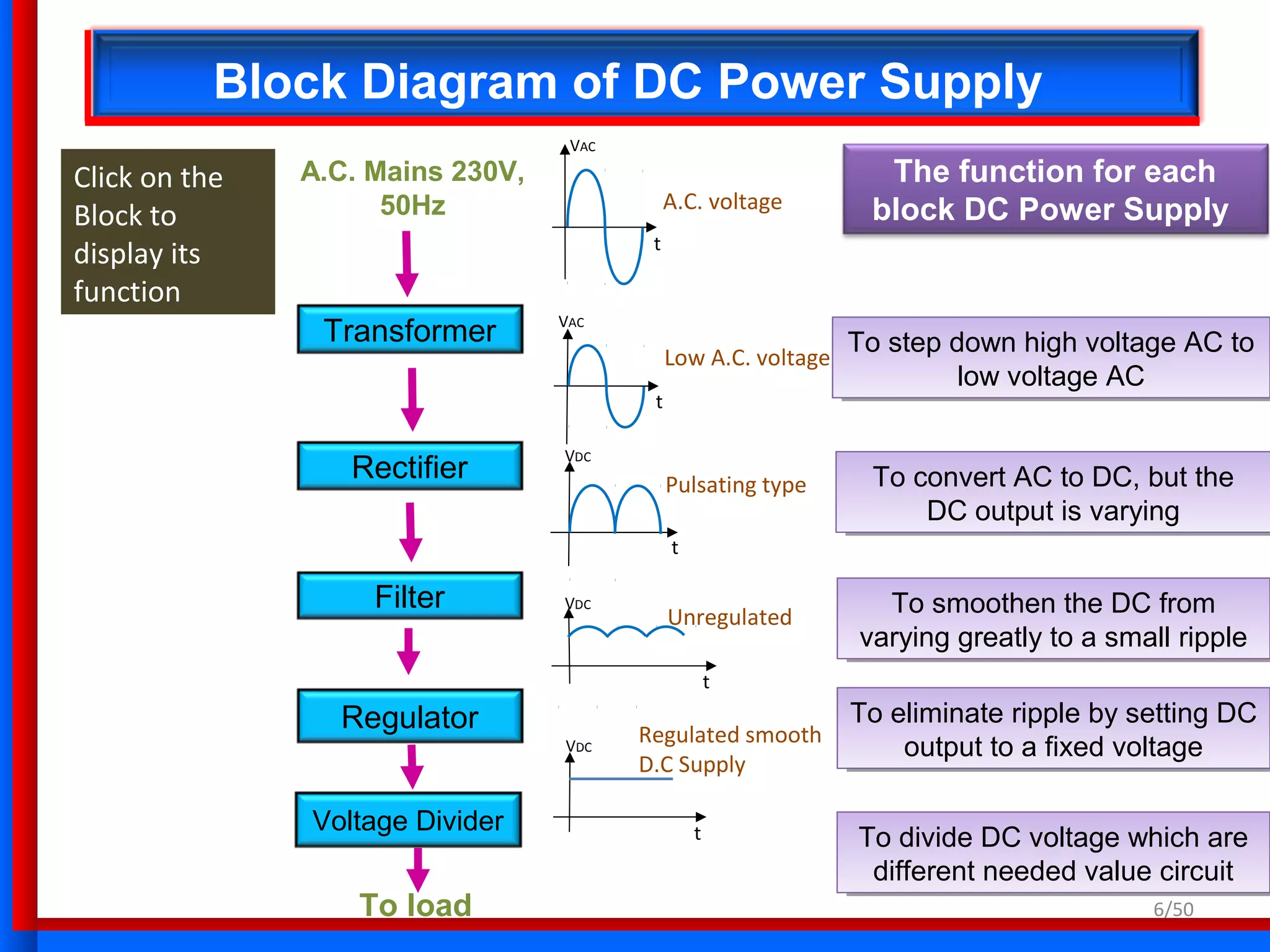
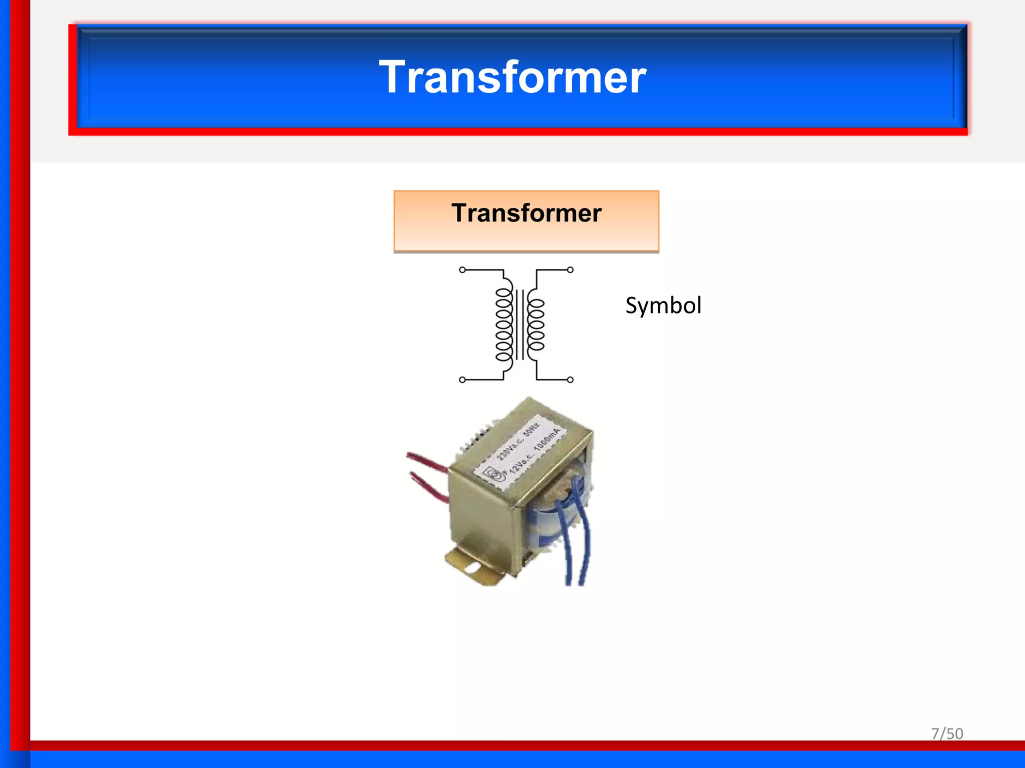
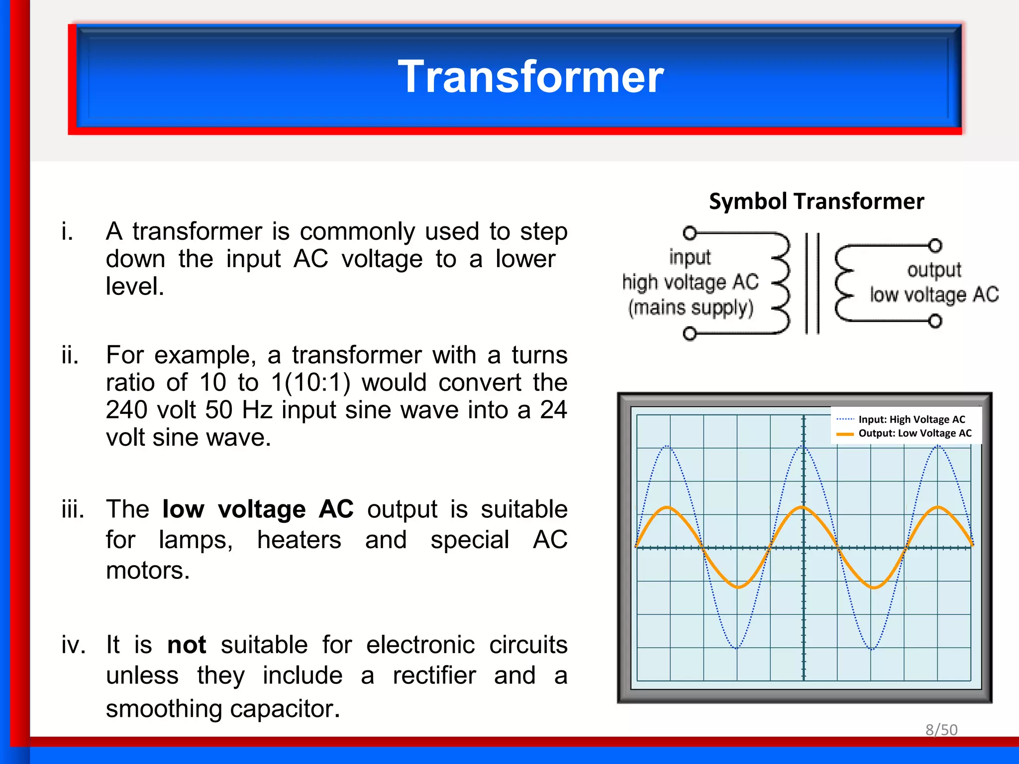
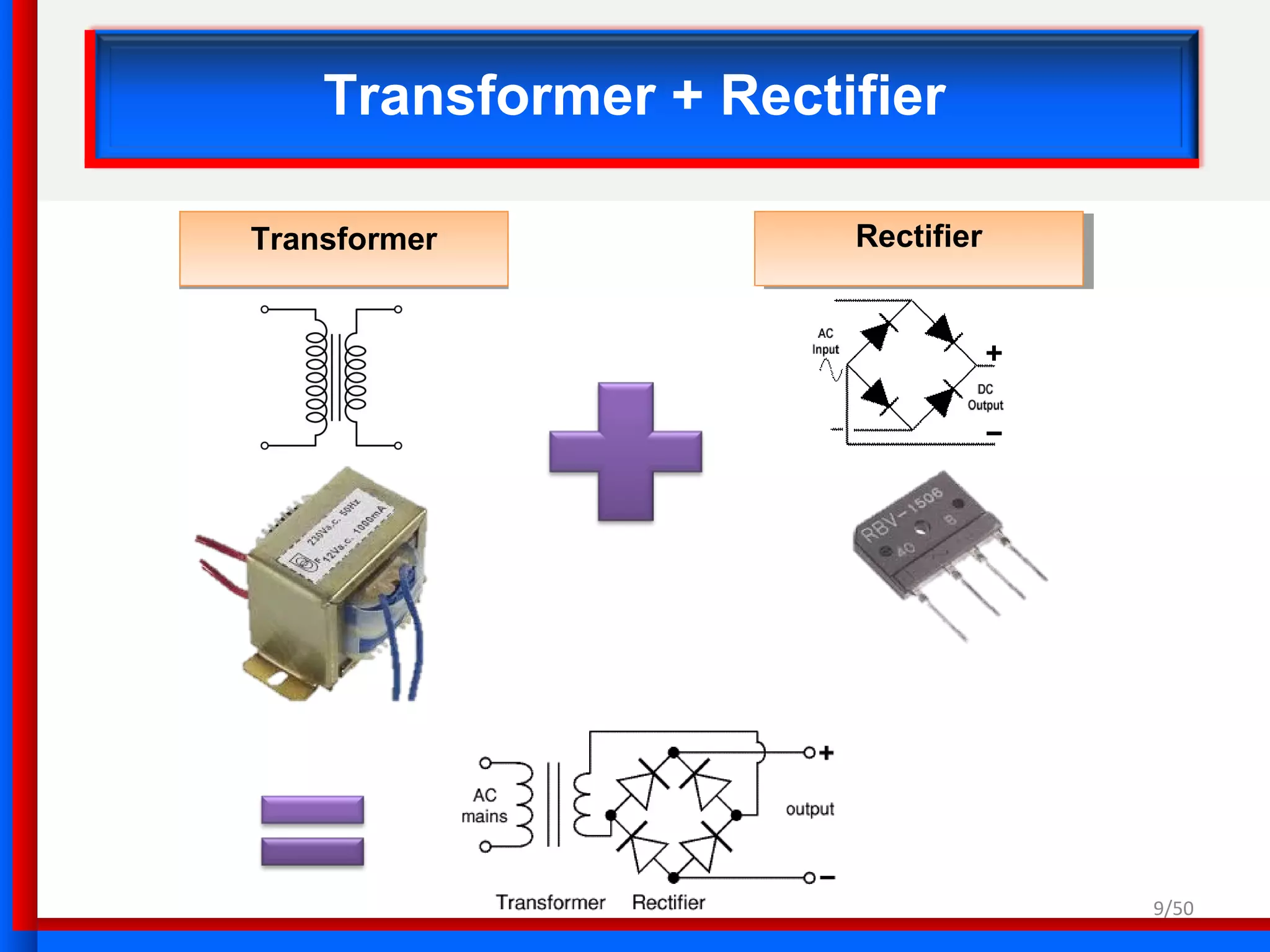
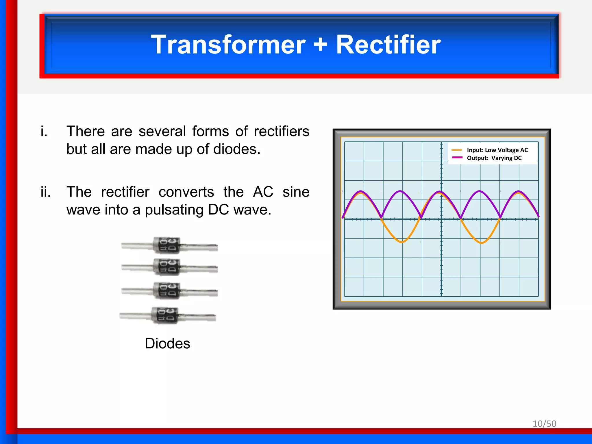
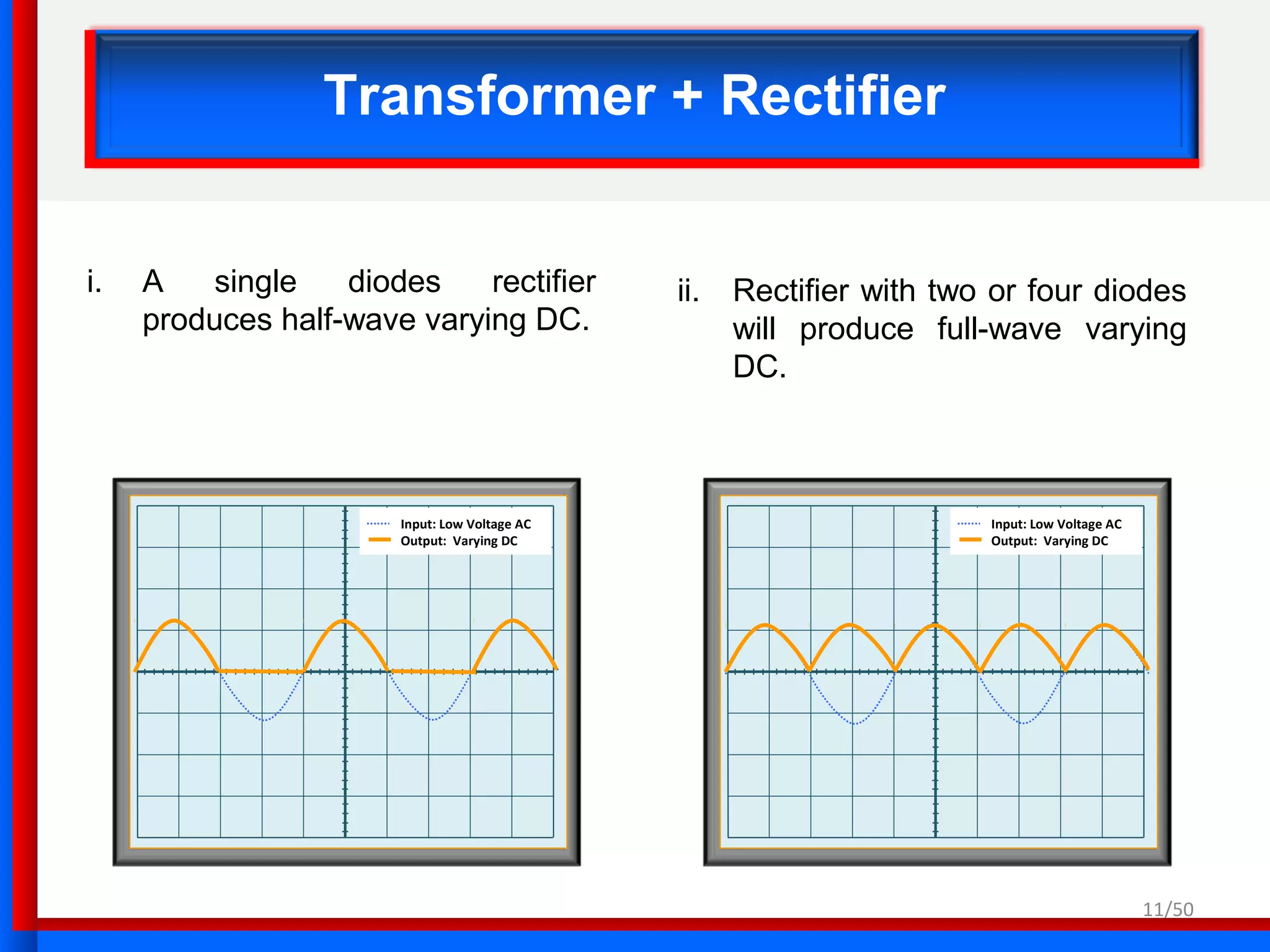
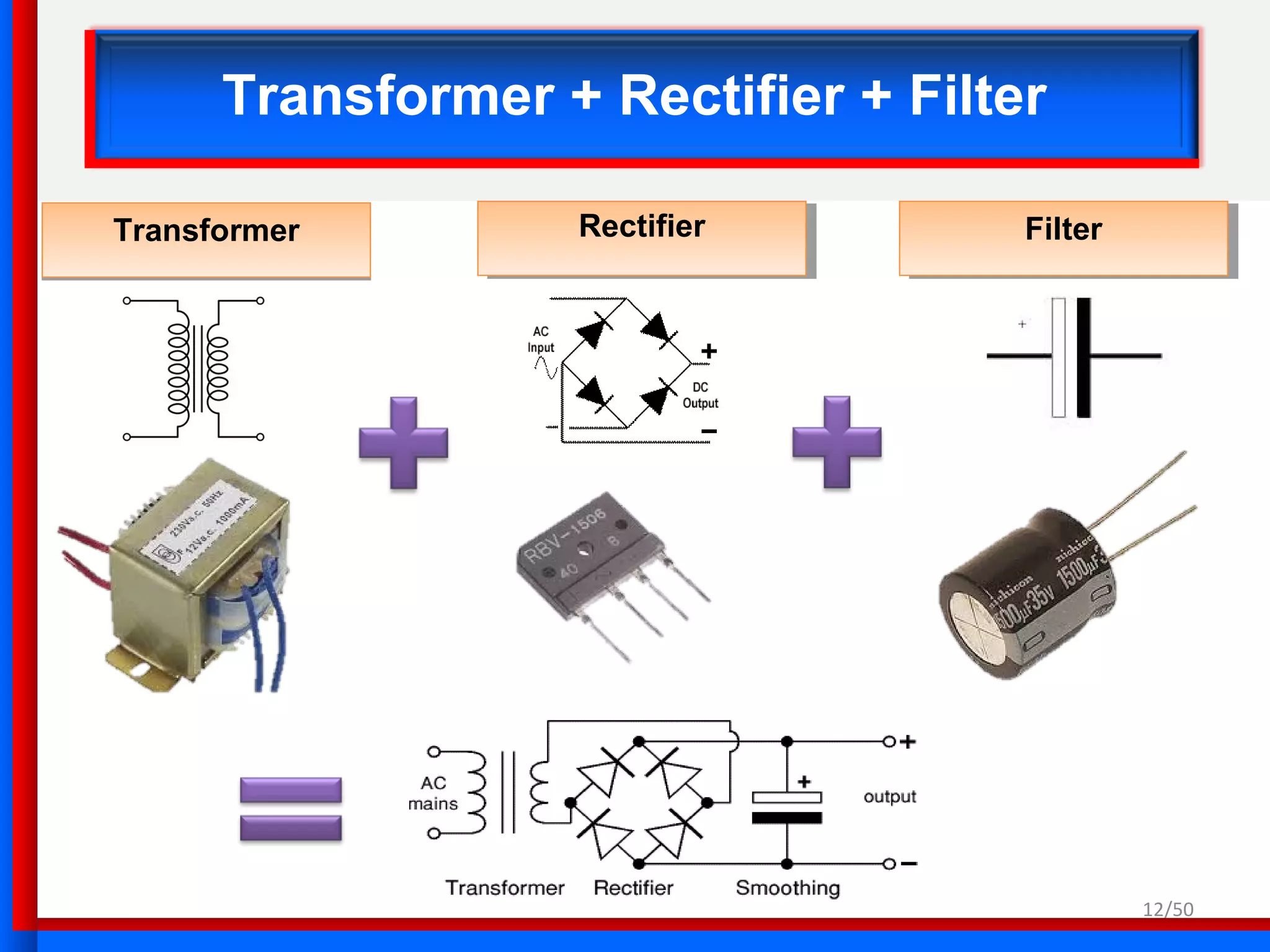
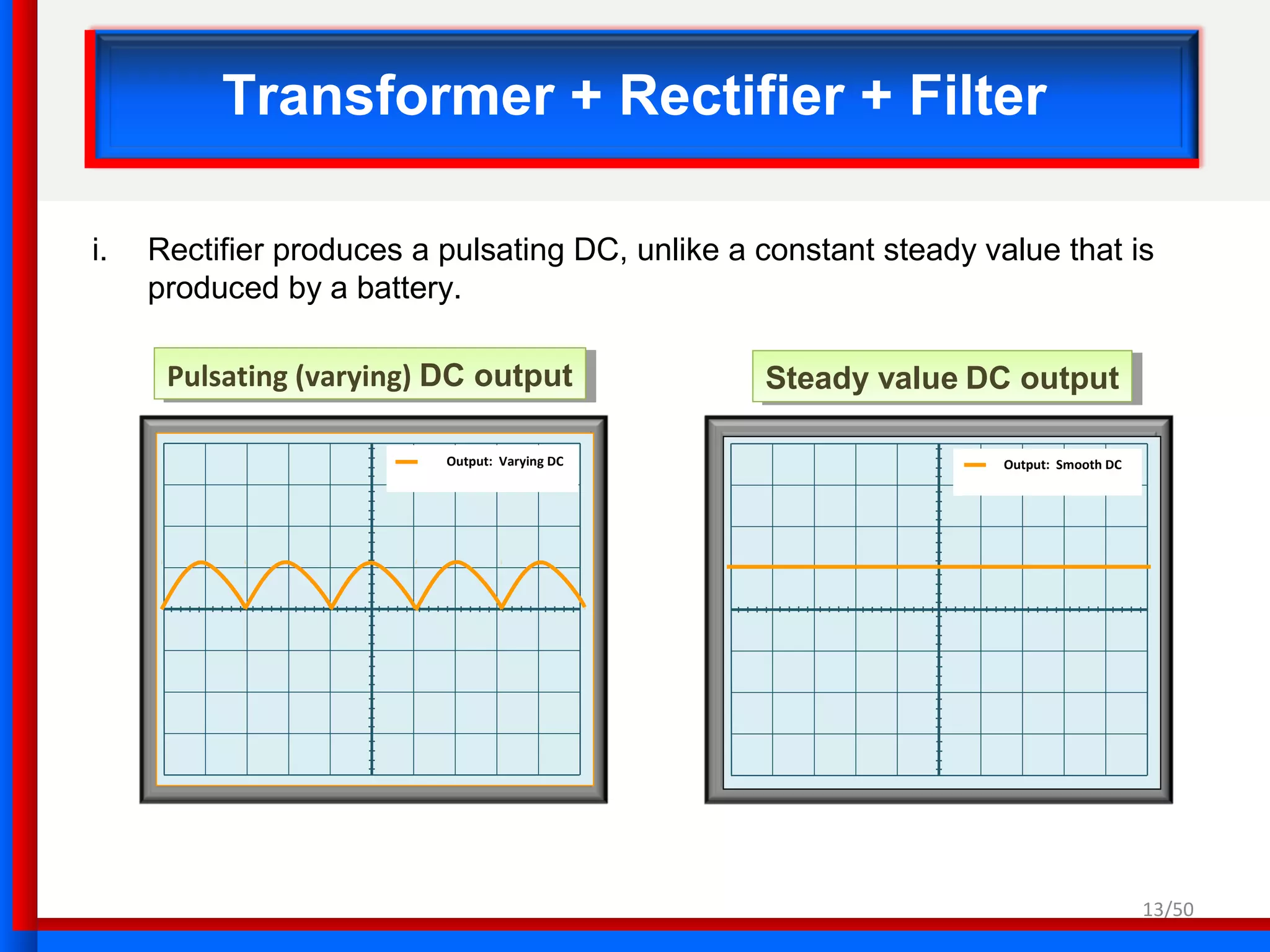
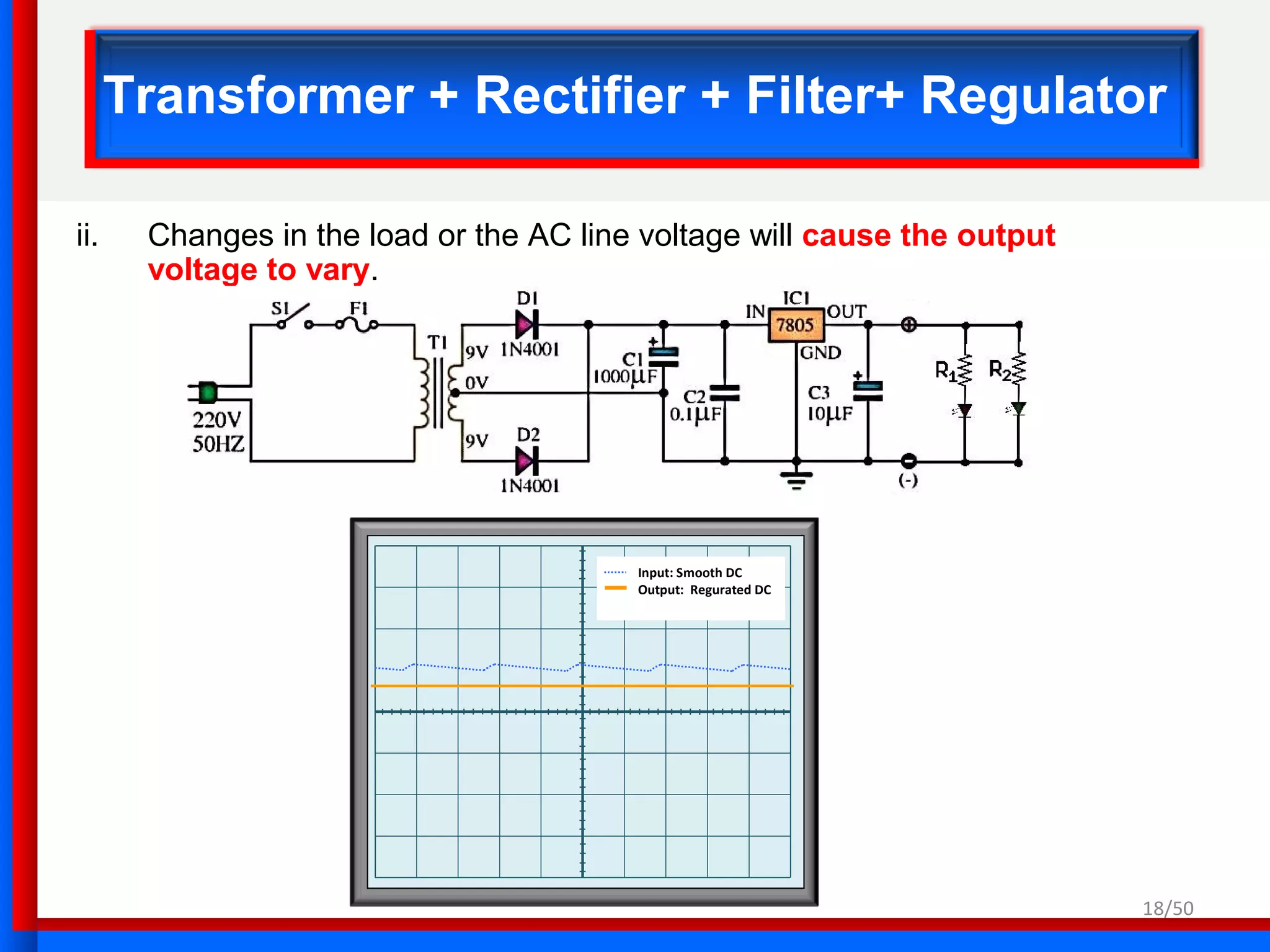
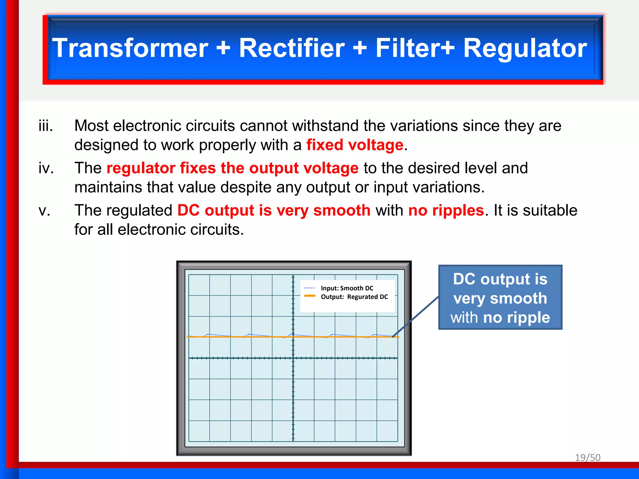
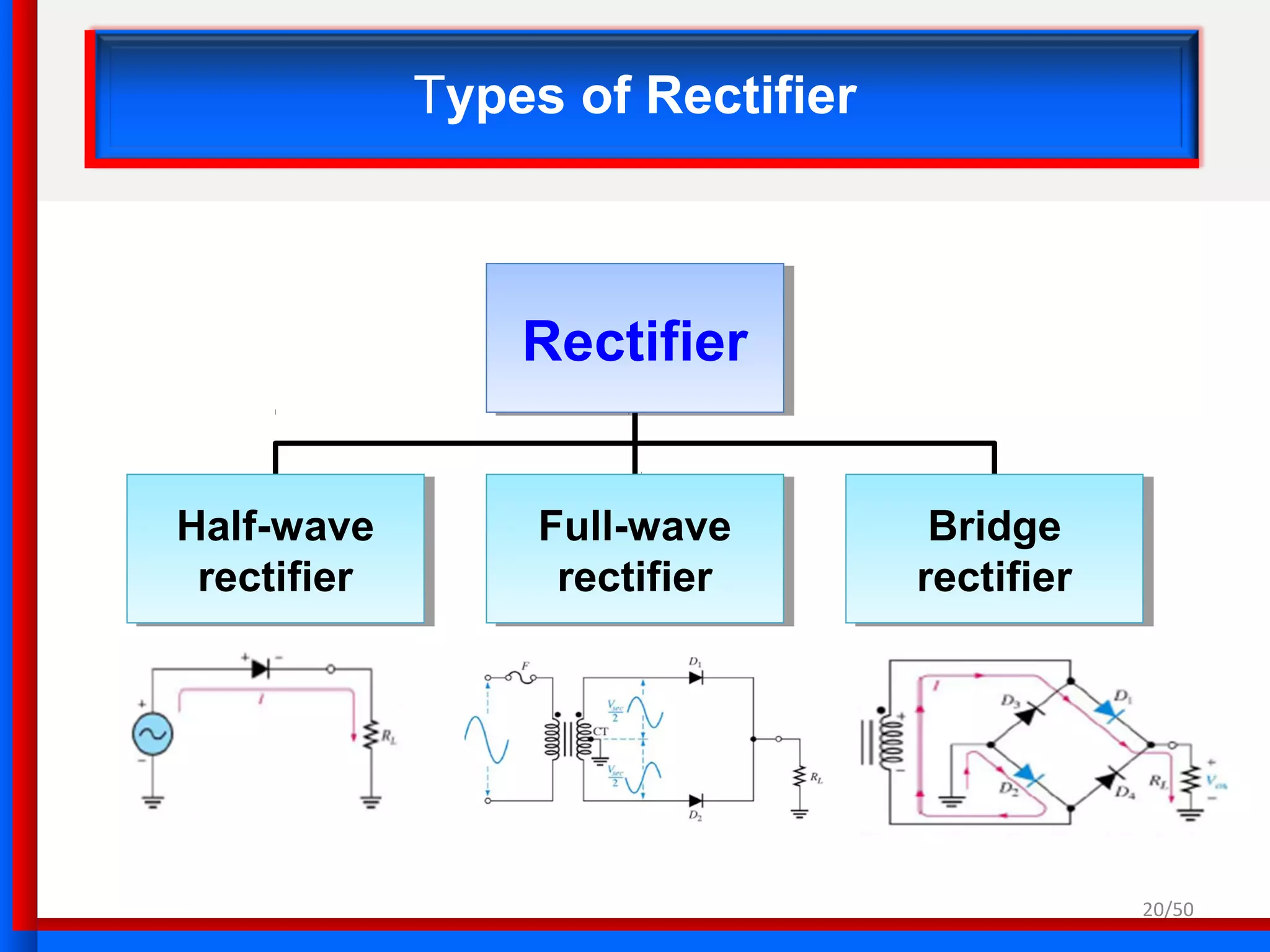
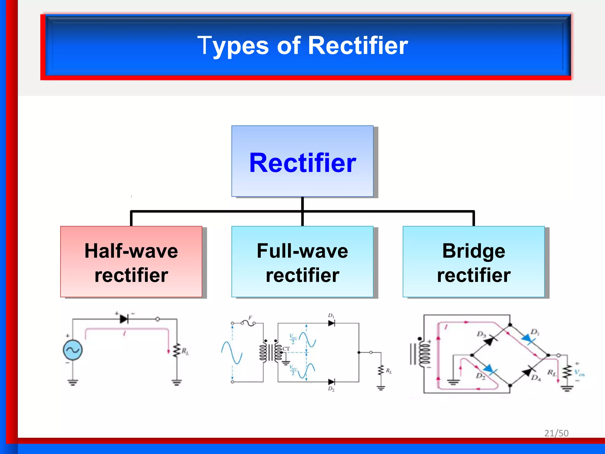
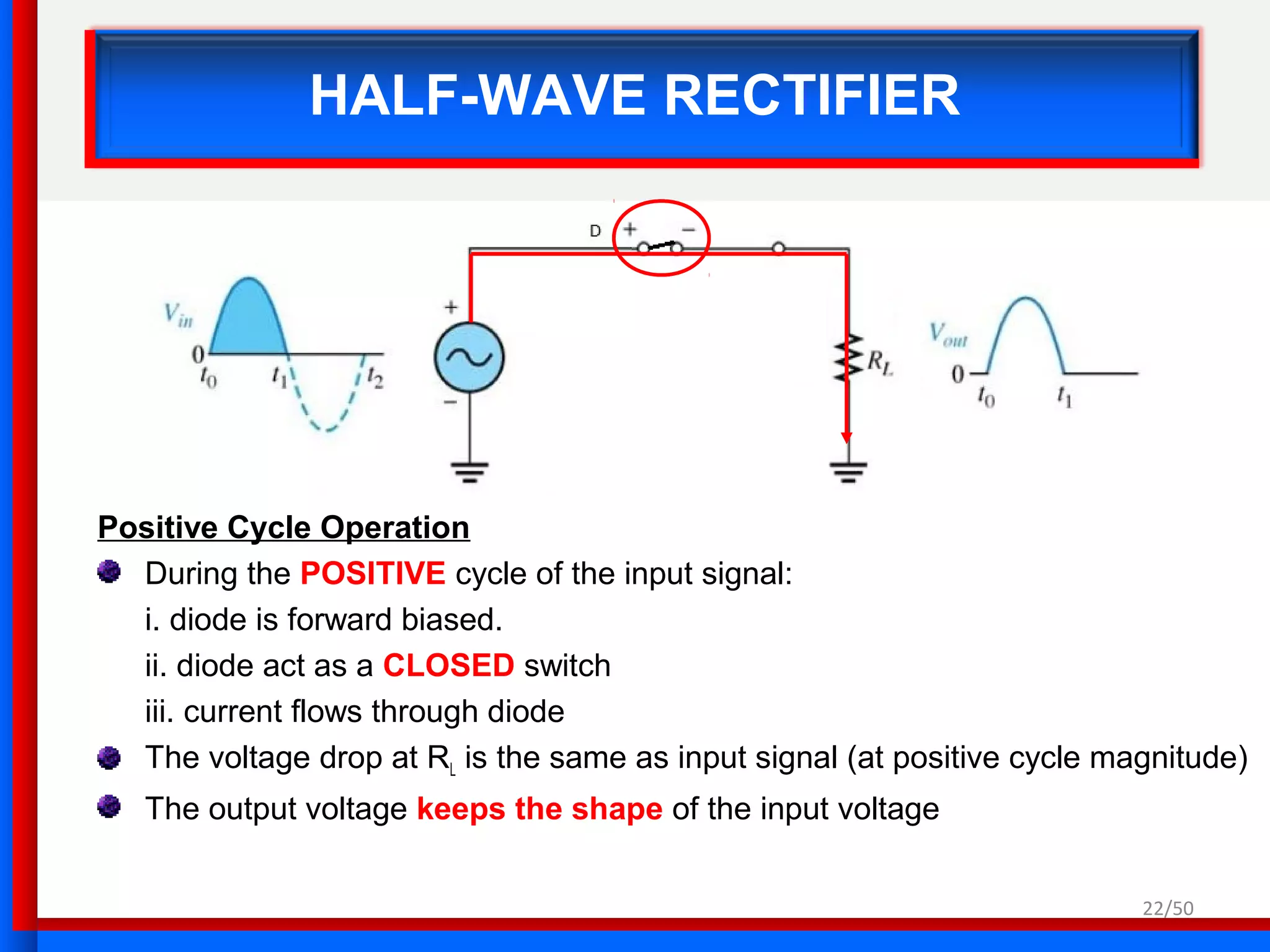
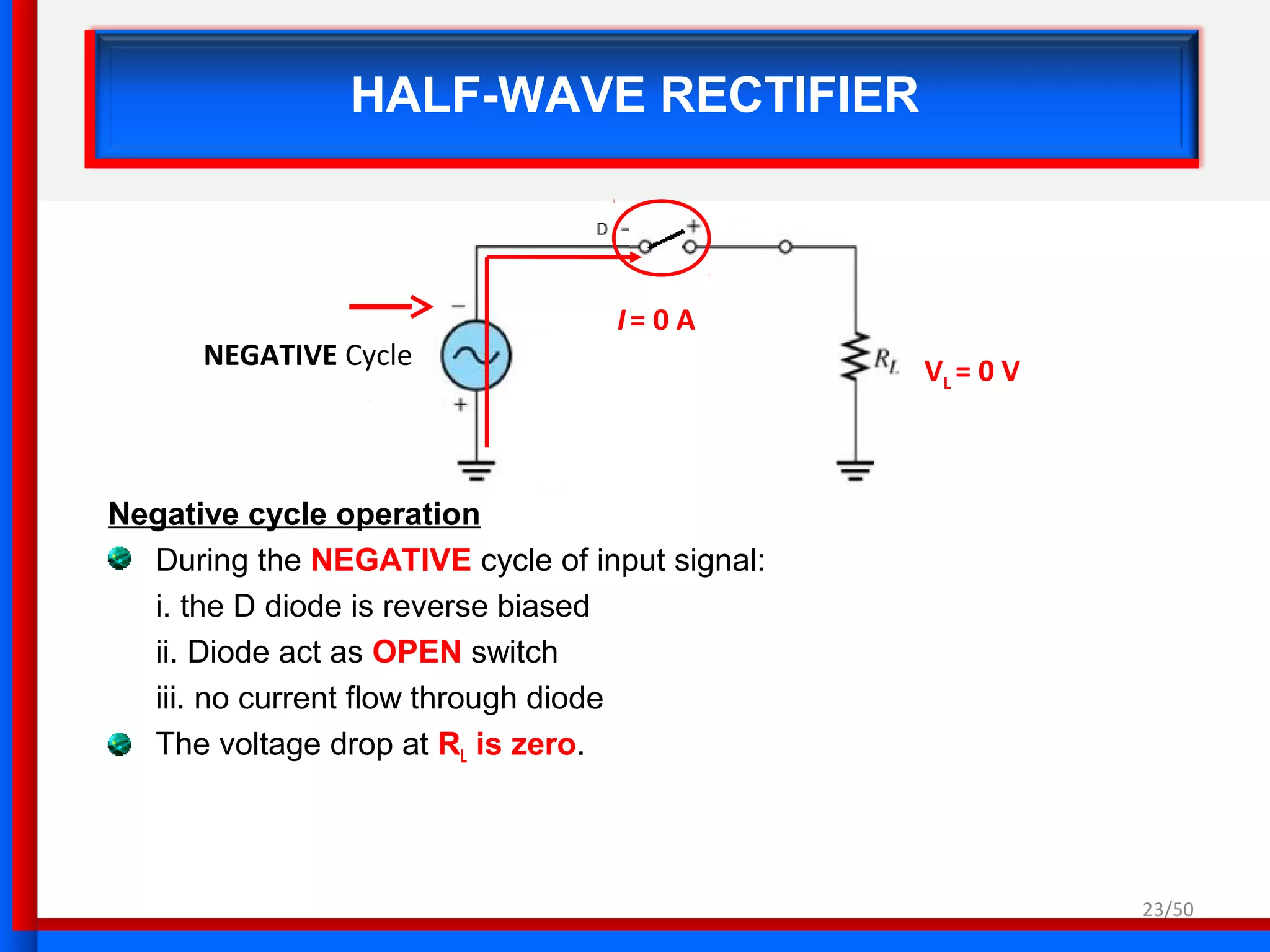
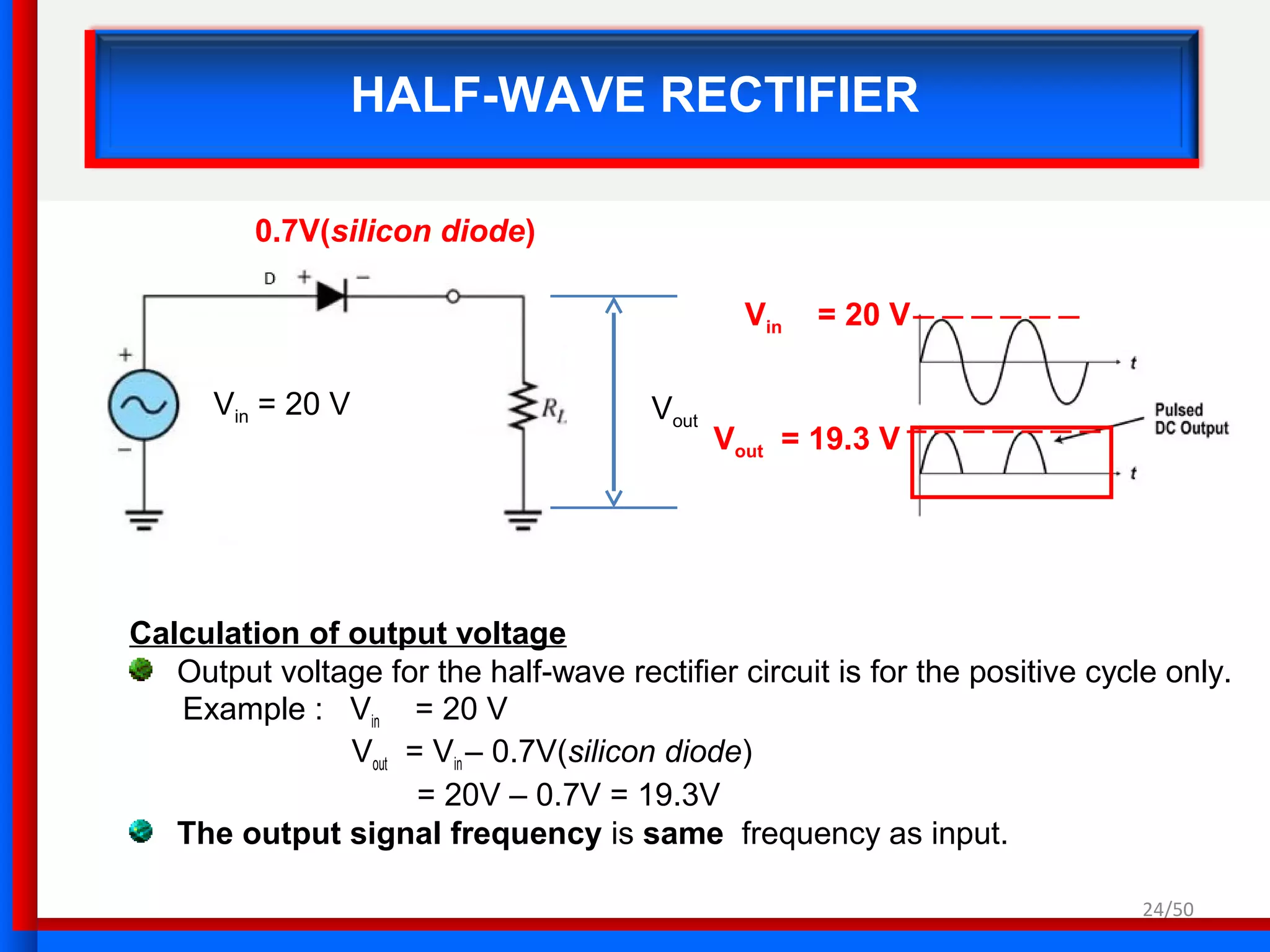
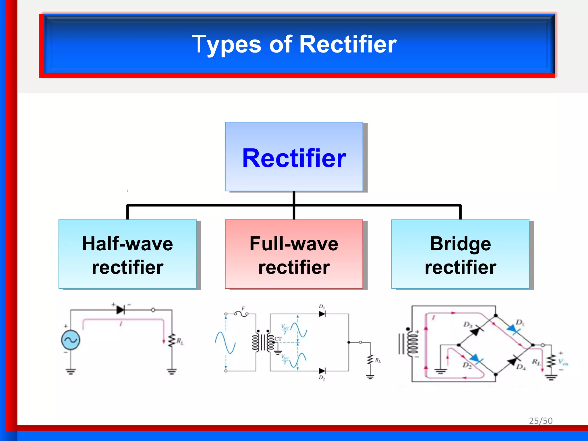
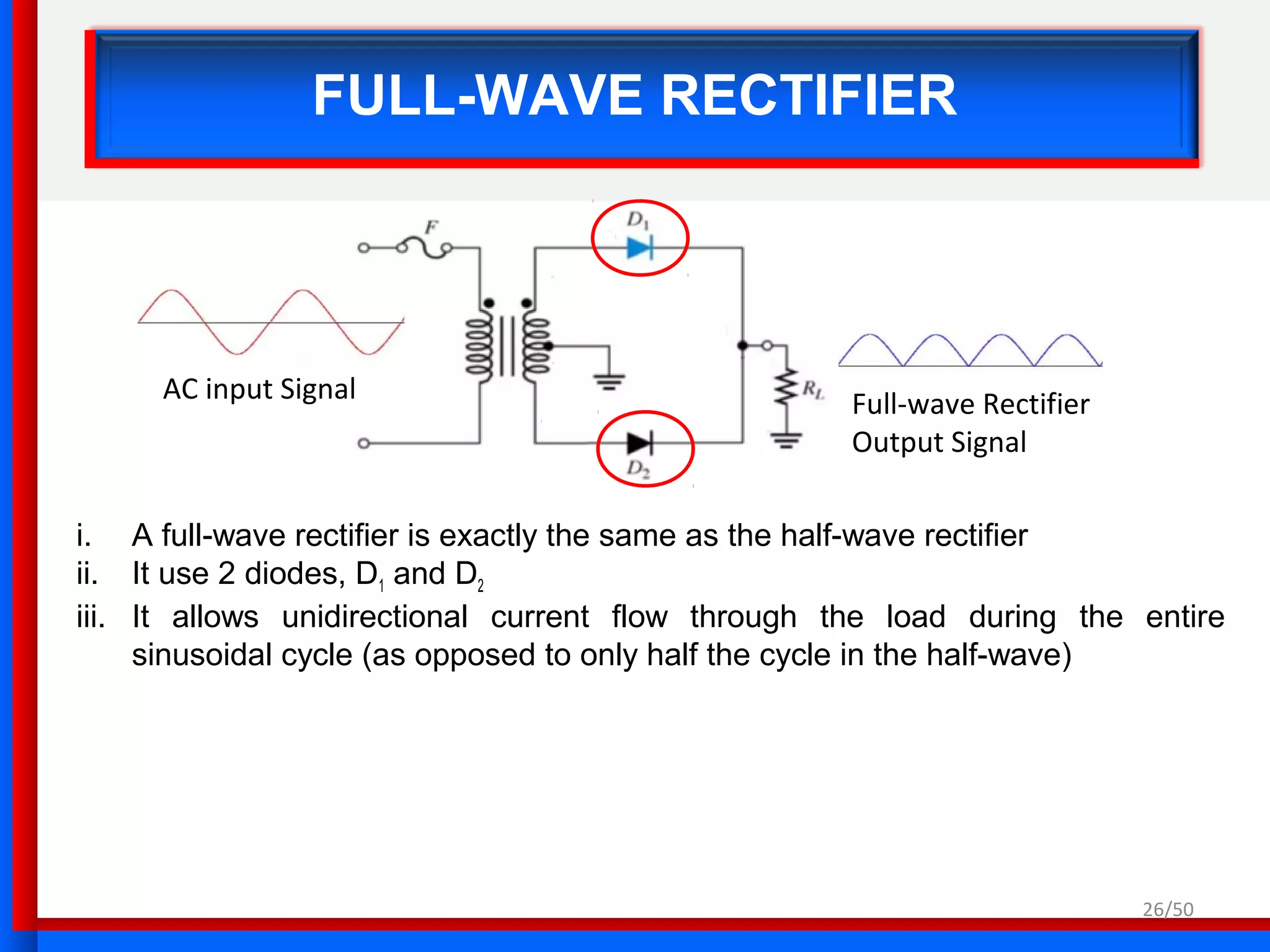
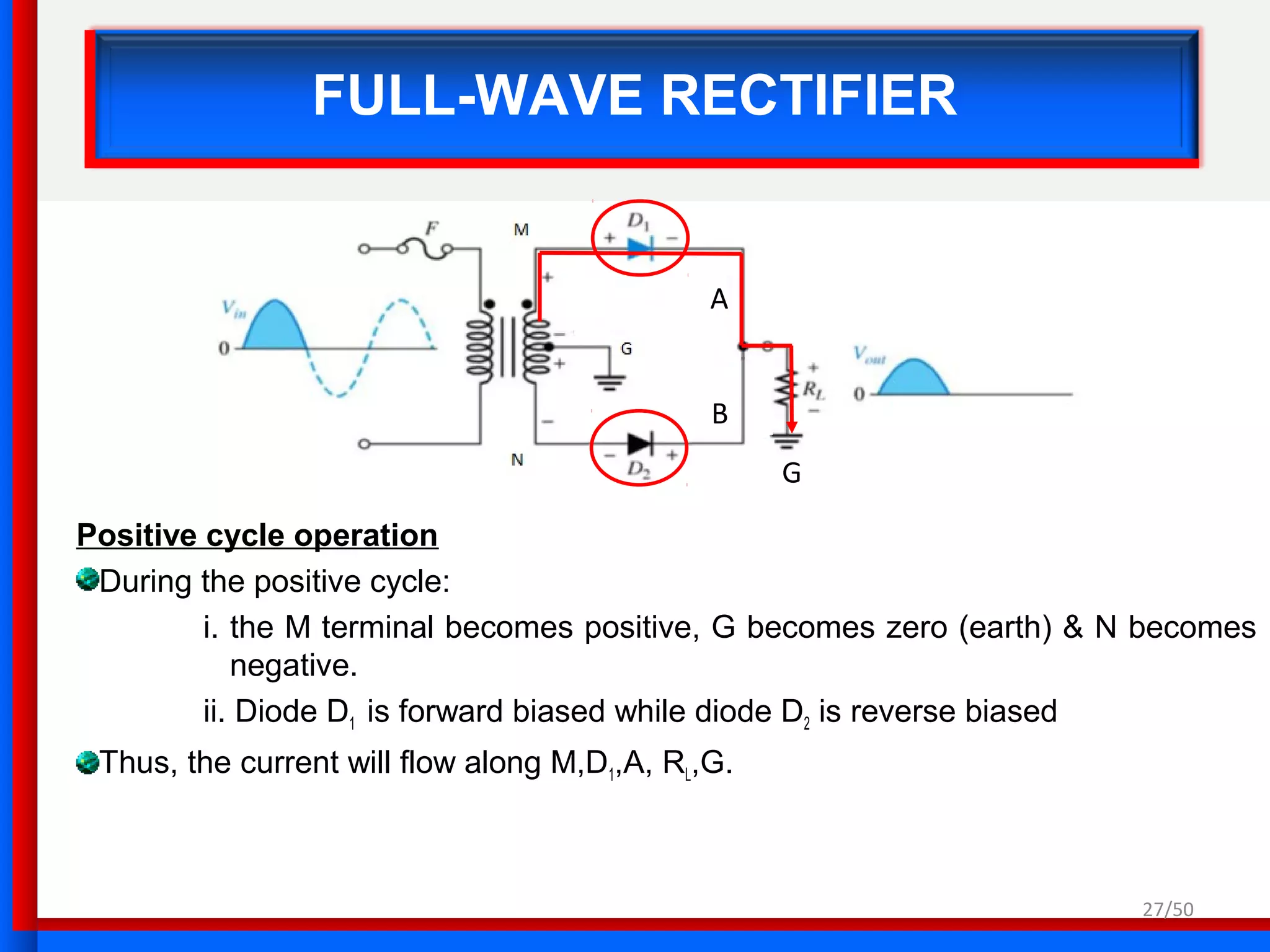
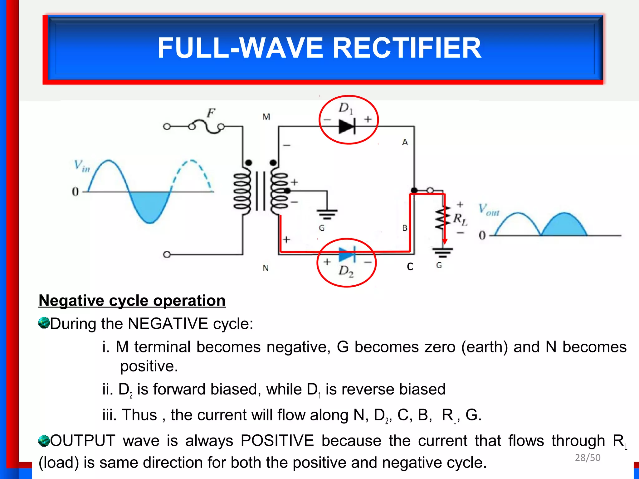
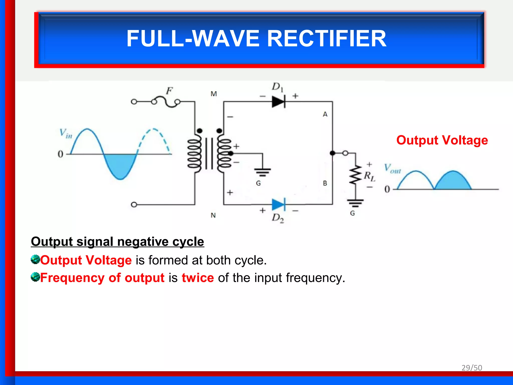
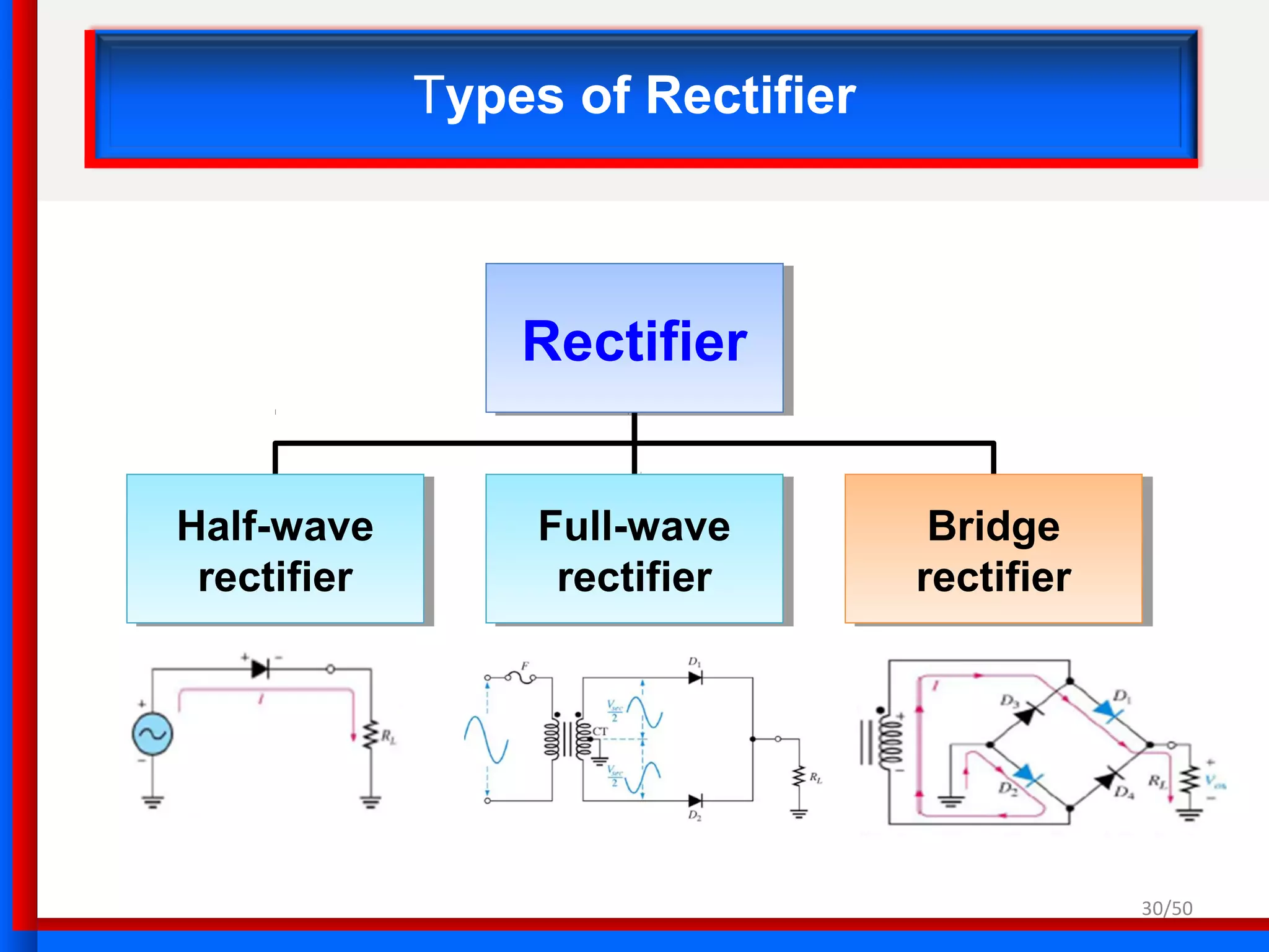
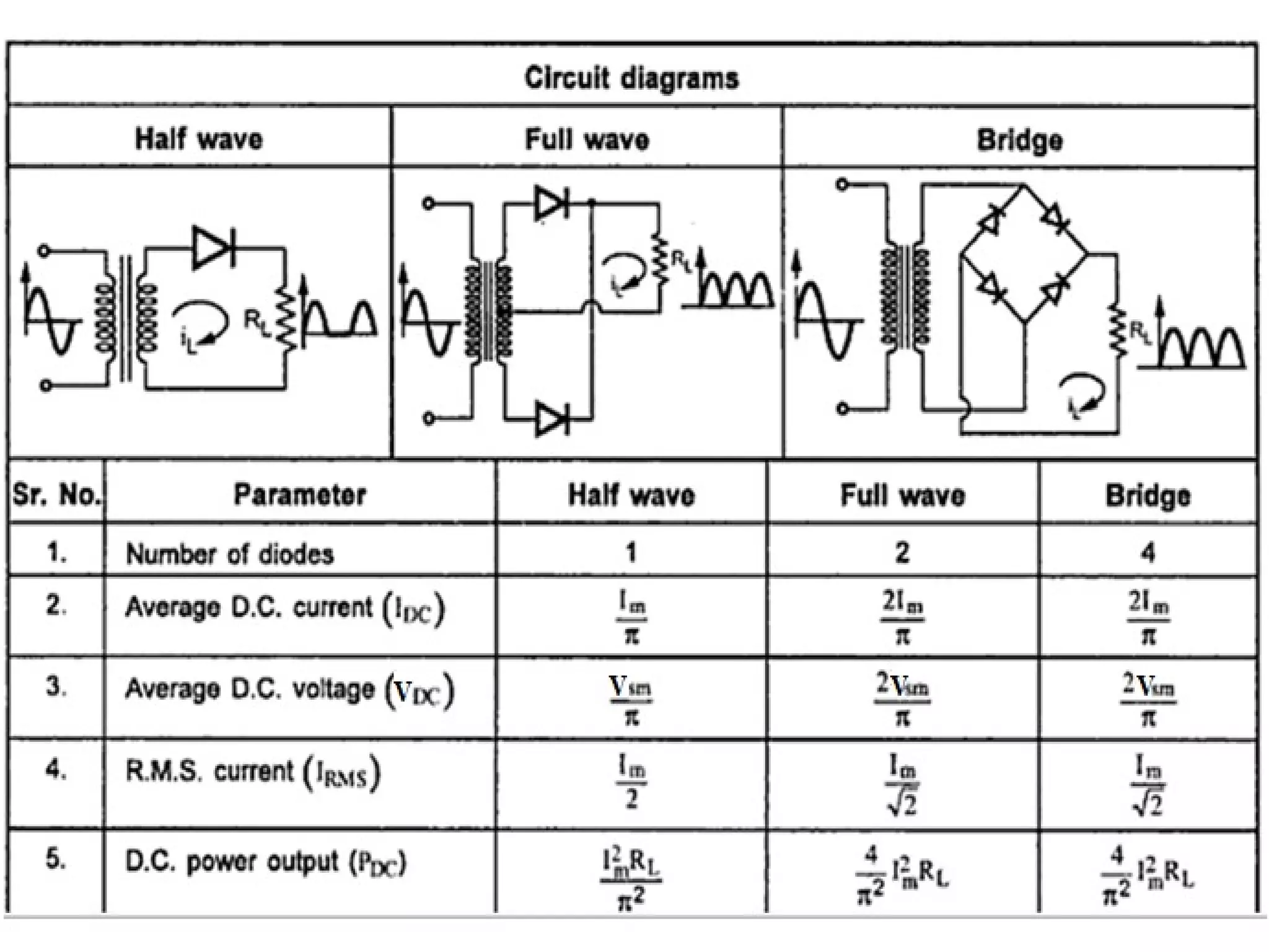
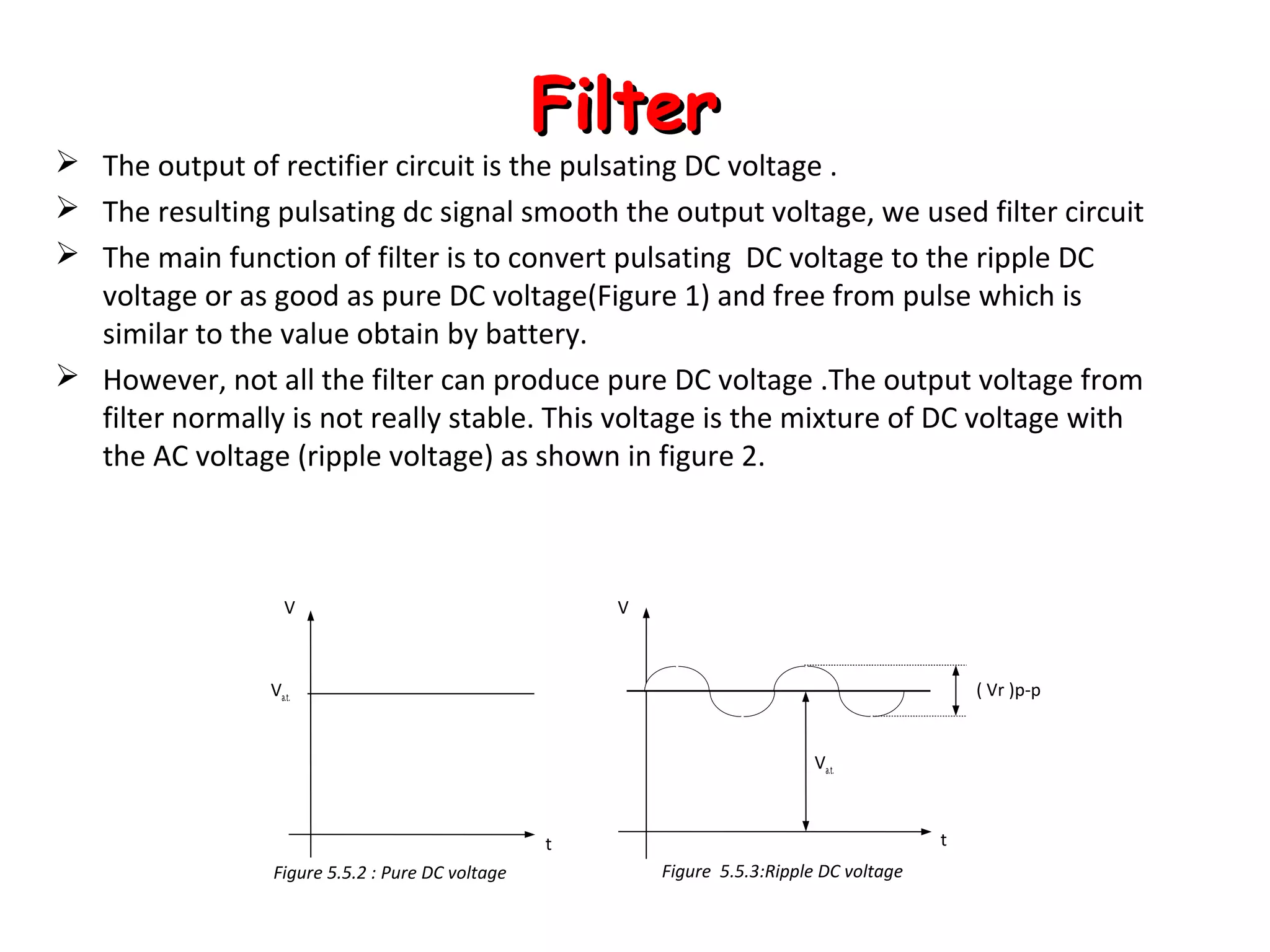
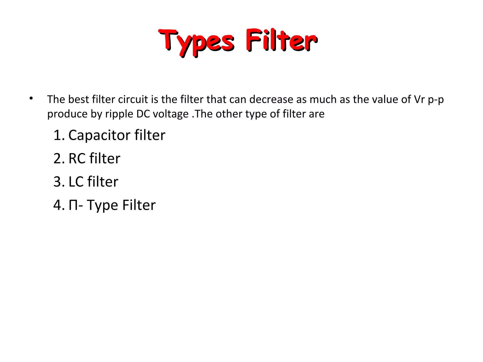
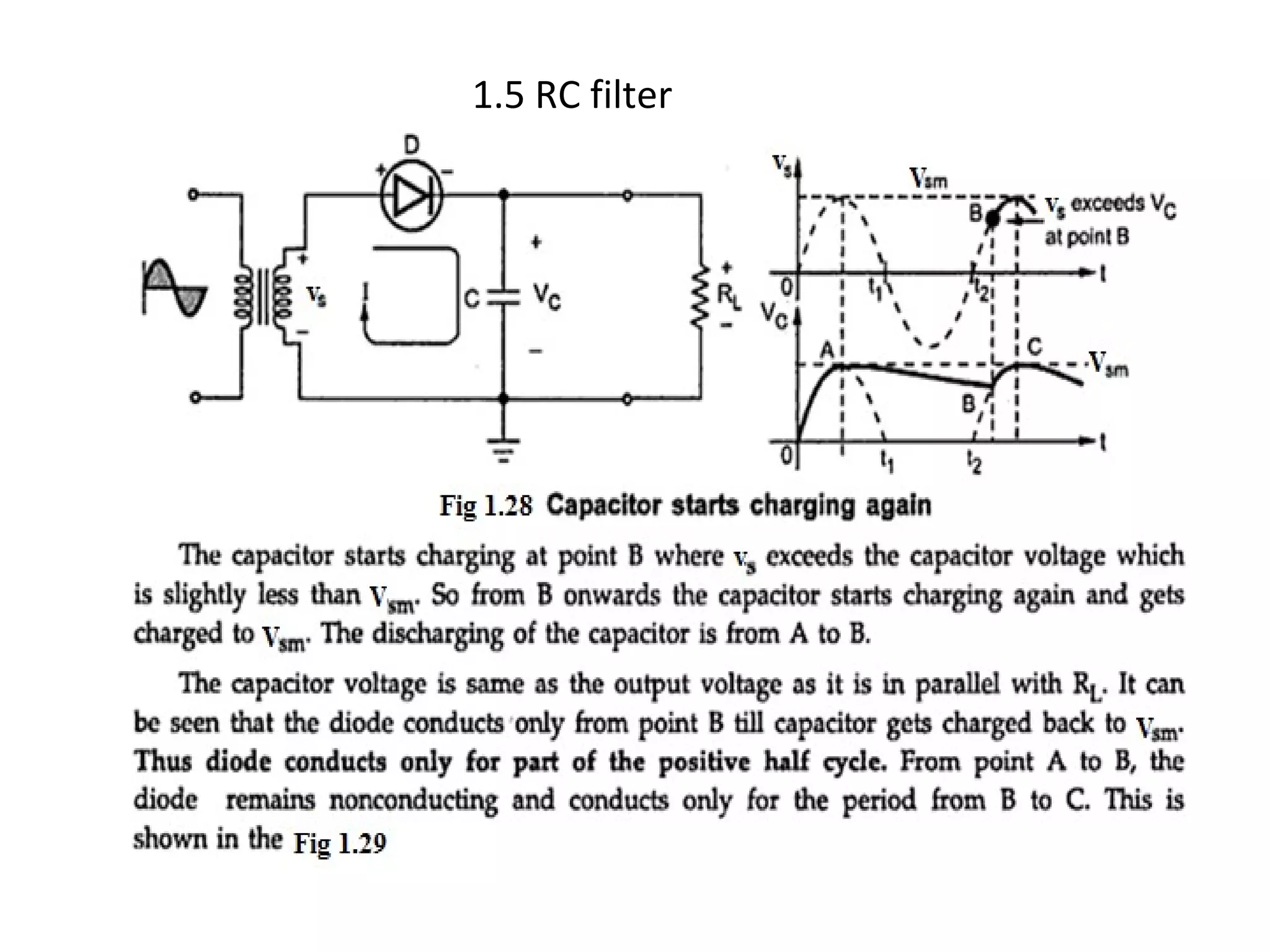
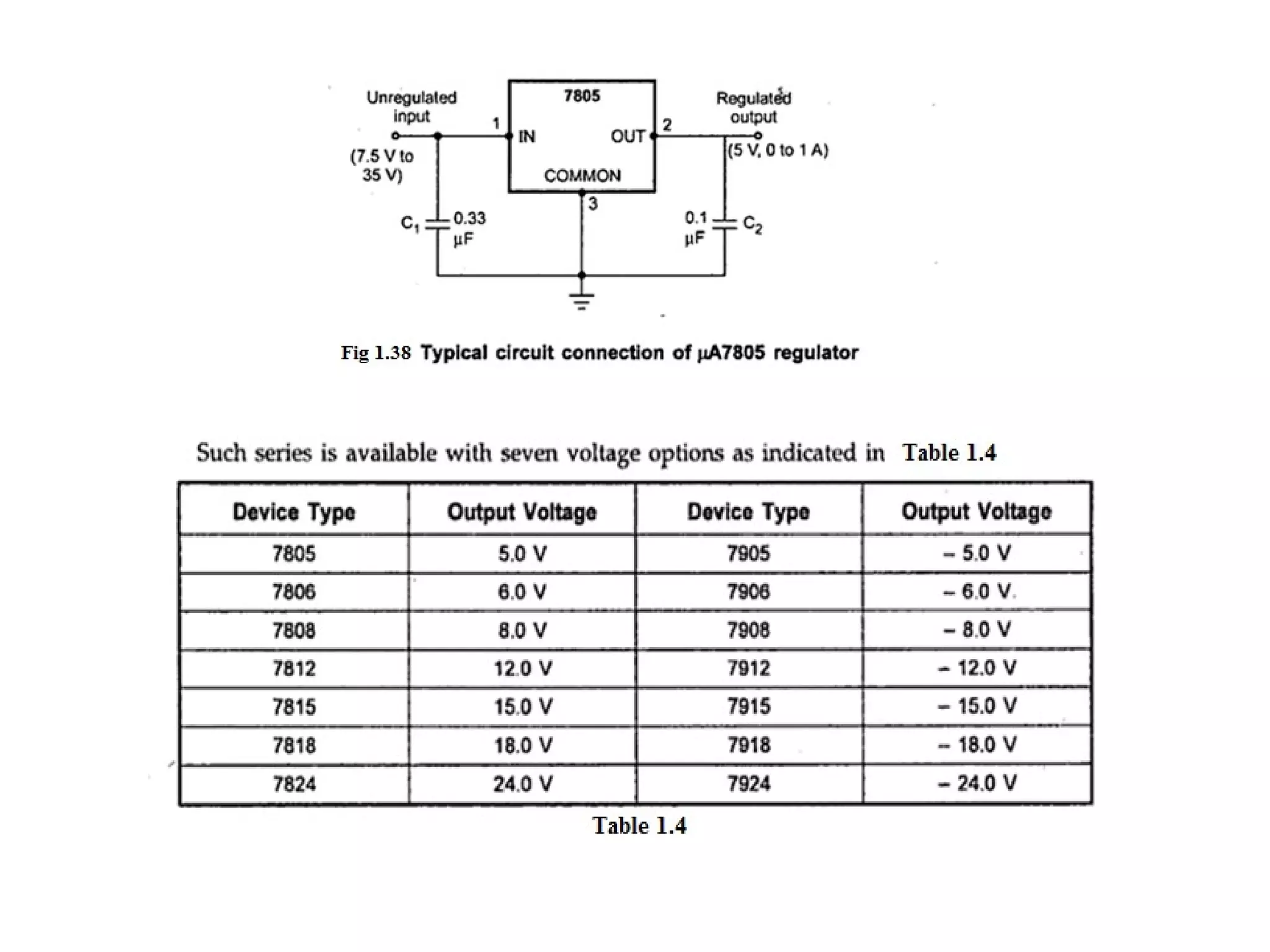
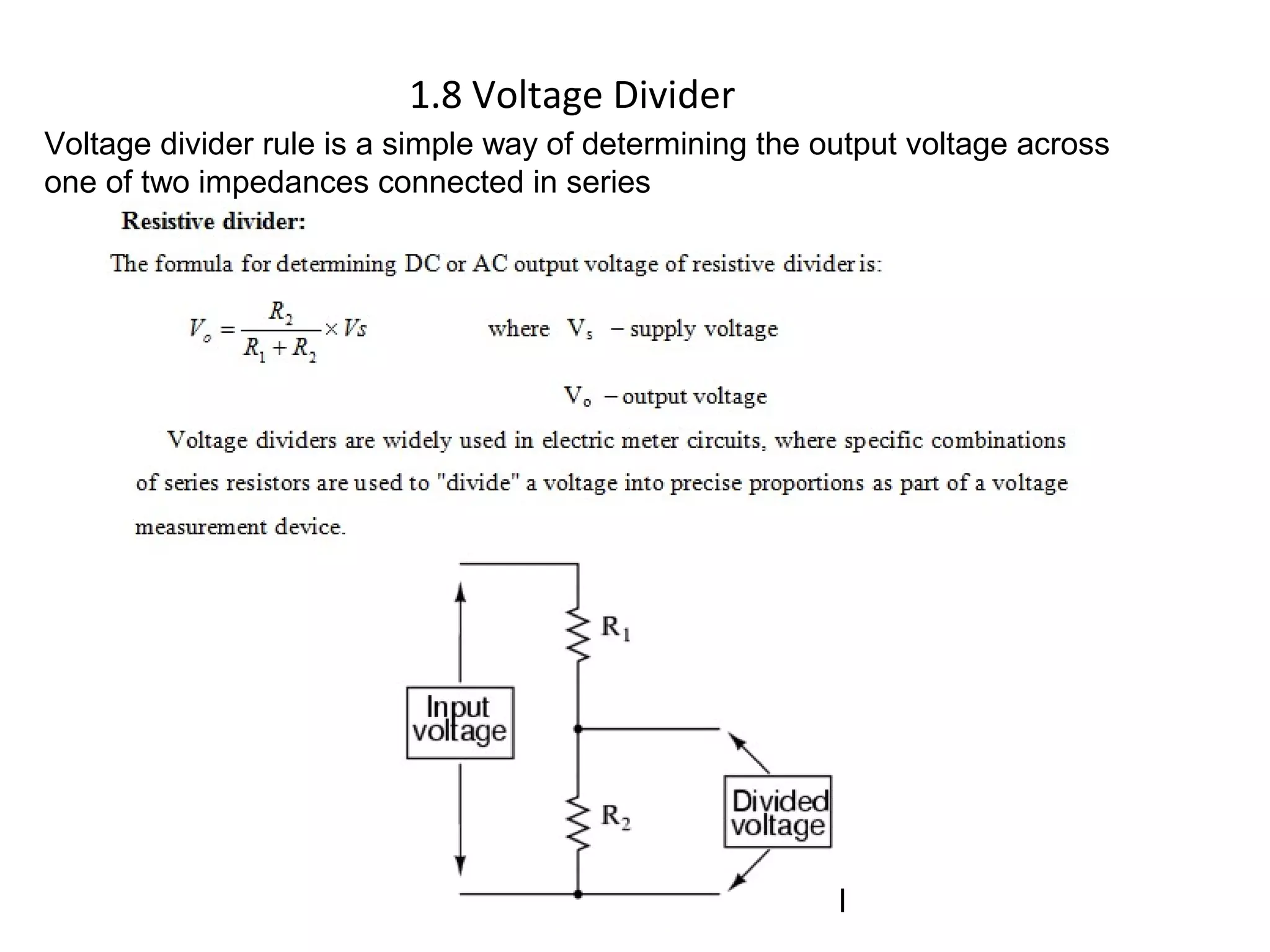
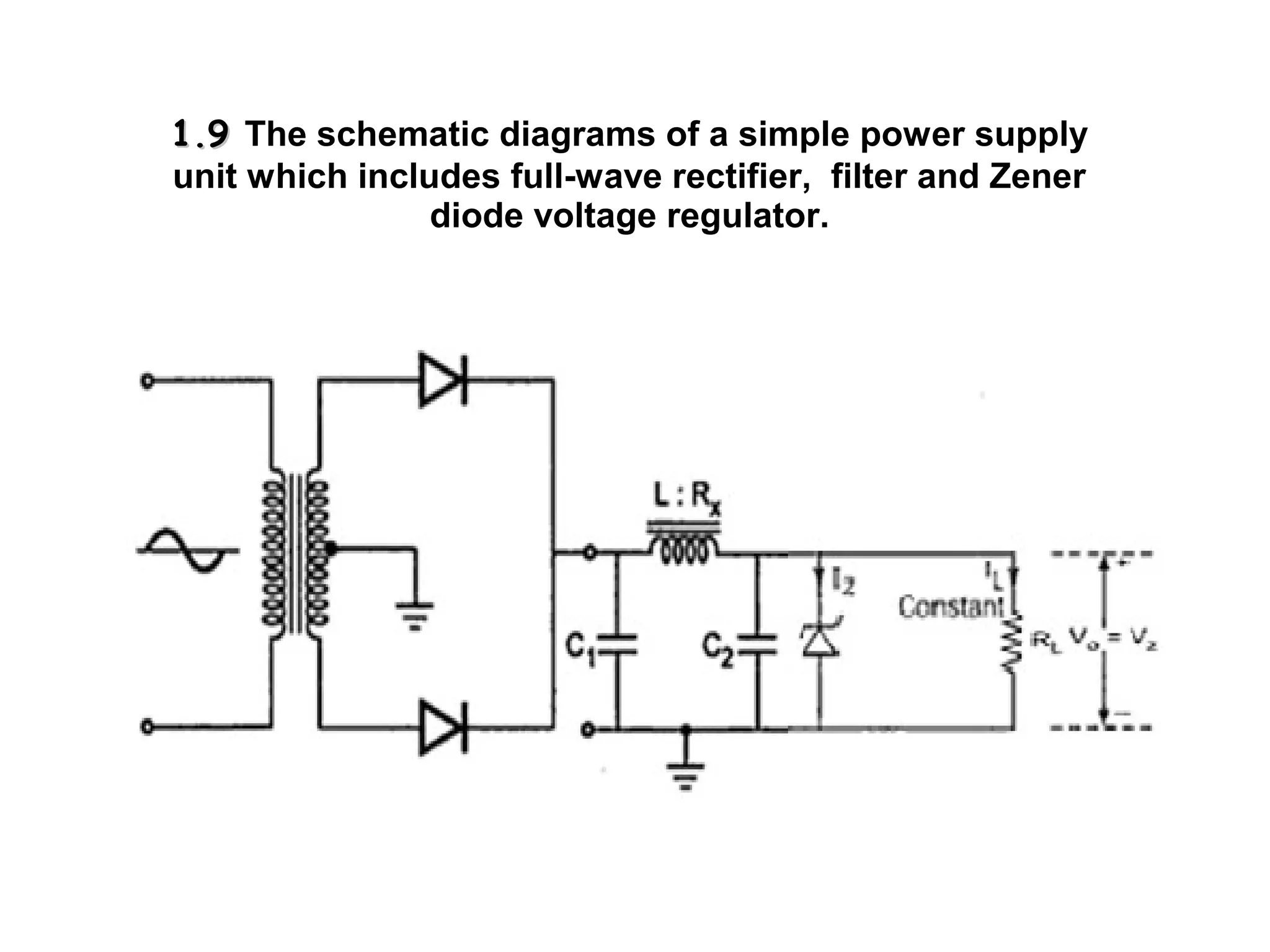
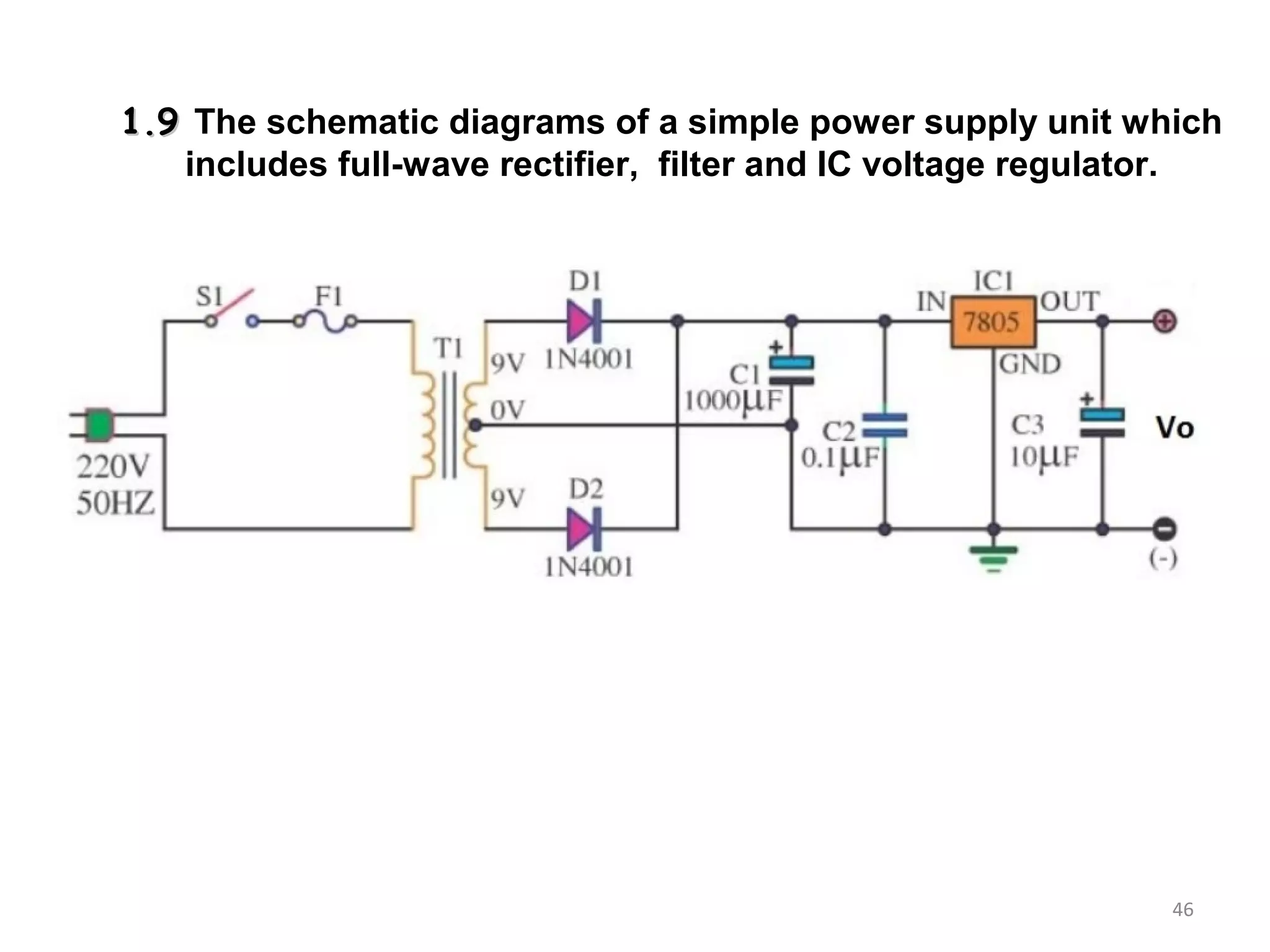
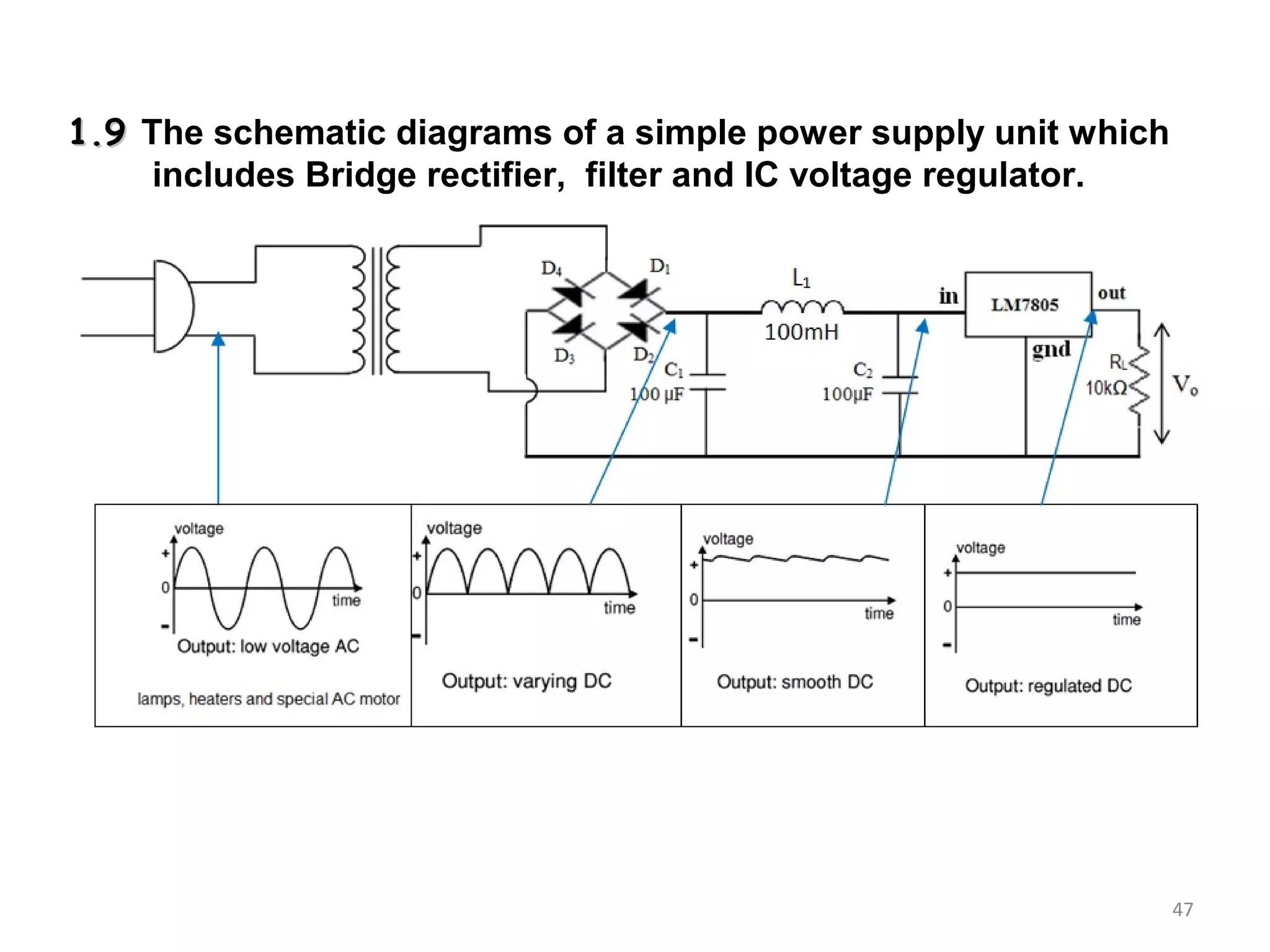
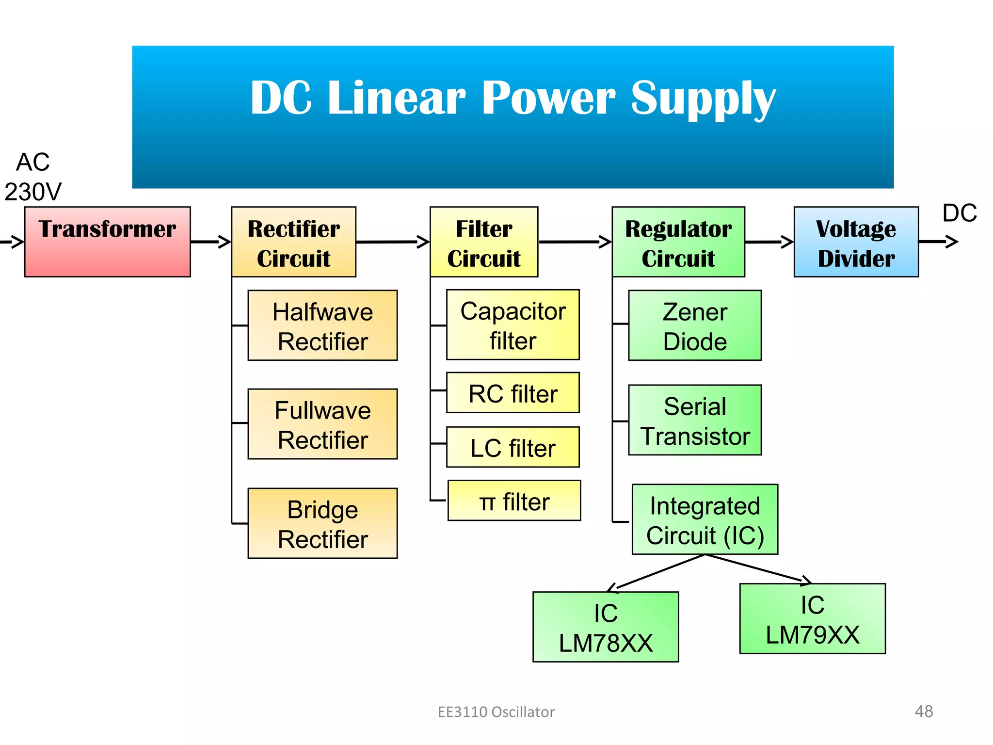
LINEAR DC
POWER SUPPLY
1/50
2/50
i. All electronic circuits need power source to
function.
ii. Power Supply Unit is a device used to
convert, regulate and transmit the required
power to the circuit to be operated.
iii. Electronic circuits made up of
semiconductors need specific value of
Direct Current (DC) voltage.
iv. Batteries are common DC voltage source
for electronic equipment especially
portables like cell phones and iPods.
v. Most non-portable equipment uses power
supplies that operate from the AC power
line but produce one or more DC outputs.
Click to “Play” the Video
3/50
POWER SUPPLY CHARACTERISTICS
i. The input is 240volt 50Hz Alternative Current (AC).
ii. A power supply unit converts the AC into DC and
provides one or more DC output voltages.
iii. Some modern electronic circuits need two or more
different voltages.
iv. Commonly required DC voltages are 48, 24, 15, 12, 9, 5,
3.3, 2.5, 1.8, 1.5, 1.2 and 1 volts.
v. A good example of a modern power supply is the one
inside a PC that furnishes 12, 5, 3.3 and 1.2 volts.
4/50
5/50
The operation of a DC power supply circuit
The importance of DC power supply units in electronic appliances
i. Power supply provide one or more fixed voltages with sufficient current to the
operating circuit.
ii. Electronic devices such as transistor radio, television and video cd players
operate fully or partly on DC power supply in the range of 0 to 24V.
iii. The successful operation of the device depends on the proper function of the
DC power supply. The power supply tries to provide a smooth, constant DC
voltage, as required by an electronic device.
iv. Major electronic appliances have built-in electronic circuits that take power
from a wall socket and convert it to the form and voltages required by the
other internal circuits of the appliance.
6/50
Block Diagram of DC Power Supply
To load
VDC
t
Regulated smooth
D.C Supply
Regulator
A.C. Mains 230V,
50Hz A.C. voltage
VAC
t
Rectifier Pulsating type
VDC
t
Filter
Unregulated
VDC
t
Voltage Divider
Transformer VAC
t
Low A.C. voltage To step down high voltage AC to
low voltage AC
To step down high voltage AC to
low voltage AC
To convert AC to DC, but the
DC output is varying
To convert AC to DC, but the
DC output is varying
To smoothen the DC from
varying greatly to a small ripple
To smoothen the DC from
varying greatly to a small ripple
To eliminate ripple by setting DC
output to a fixed voltage
To eliminate ripple by setting DC
output to a fixed voltage
To divide DC voltage which are
different needed value circuit
To divide DC voltage which are
different needed value circuit
The function for each
block DC Power Supply
Click on the
Block to
display its
function
7/50
Transformer
TransformerTransformer
Symbol
Input: High Voltage AC
Output: Low Voltage AC
Transformer
i. A transformer is commonly used to step
down the input AC voltage to a lower
level.
ii. For example, a transformer with a turns
ratio of 10 to 1(10:1) would convert the
240 volt 50 Hz input sine wave into a 24
volt sine wave.
iii. The low voltage AC output is suitable
for lamps, heaters and special AC
motors.
iv. It is not suitable for electronic circuits
unless they include a rectifier and a
smoothing capacitor.
Symbol Transformer
8/50
9/50
Transformer + Rectifier
TransformerTransformer RectifierRectifier
10/50
Transformer + Rectifier
i. There are several forms of rectifiers
but all are made up of diodes.
ii. The rectifier converts the AC sine
wave into a pulsating DC wave.
Input: Low Voltage AC
Output: Varying DC
Diodes
Input: Low Voltage AC
Output: Varying DC
Input: Low Voltage AC
Output: Varying DC
11/50
Transformer + Rectifier
i. A single diodes rectifier
produces half-wave varying DC.
ii. Rectifier with two or four diodes
will produce full-wave varying
DC.
12/50
Transformer + Rectifier + Filter
TransformerTransformer RectifierRectifier FilterFilter
13/50
Transformer + Rectifier + Filter
i. Rectifier produces a pulsating DC, unlike a constant steady value that is
produced by a battery.
Output: Smooth DCOutput: Varying DC
Pulsating (varying) DC outputPulsating (varying) DC output Steady value DC outputSteady value DC output
Input: Varying DC
Output: Smooth DC
14/50
Transformer + Rectifier + Filter
ii. A filter is then used to remove the pulsations and create a constant
output.
Output: Varying DC
Pulsating (varying) DC outputPulsating (varying) DC output Constant / Smooth DC outputConstant / Smooth DC output
15/50
Transformer + Rectifier + Filter
iii. The most common filter is a large capacitor.
iv. The filtered DC output have small ripples. It is suitable for most electronic
circuits.
Input: Varying DC
Output: Smooth DC
RectifierRectifier
16/50
Transformer + Rectifier + Filter+ Regulator
TransformerTransformer FilterFilter RegulatorRegulator
Input: Smooth DC
Output: Regurated DC
17/50
Transformer + Rectifier + Filter+ Regulator
i. The regulator is a component that helps to maintain a fixed or
constant output voltage.
RegulatorRegulator
Input: Smooth DC
Output: Regurated DC
18/50
Transformer + Rectifier + Filter+ Regulator
ii. Changes in the load or the AC line voltage will cause the output
voltage to vary.
Input: Smooth DC
Output: Regurated DC
19/50
Transformer + Rectifier + Filter+ Regulator
iii. Most electronic circuits cannot withstand the variations since they are
designed to work properly with a fixed voltage.
iv. The regulator fixes the output voltage to the desired level and
maintains that value despite any output or input variations.
v. The regulated DC output is very smooth with no ripples. It is suitable
for all electronic circuits.
Input: Smooth DC
Output: Regurated DC
DC output is
very smooth
with no ripple
20/50
Types of Rectifier
RectifierRectifier
Half-wave
rectifier
Half-wave
rectifier
Full-wave
rectifier
Full-wave
rectifier
Bridge
rectifier
Bridge
rectifier
21/50
Types of Rectifier
RectifierRectifier
Full-wave
rectifier
Full-wave
rectifier
Bridge
rectifier
Bridge
rectifier
Half-wave
rectifier
Half-wave
rectifier
22/50
HALF-WAVE RECTIFIER
Positive Cycle Operation
During the POSITIVE cycle of the input signal:
i. diode is forward biased.
ii. diode act as a CLOSED switch
iii. current flows through diode
The voltage drop at RL is the same as input signal (at positive cycle magnitude)
The output voltage keeps the shape of the input voltage
23/50
HALF-WAVE RECTIFIER
Negative cycle operation
During the NEGATIVE cycle of input signal:
i. the D diode is reverse biased
ii. Diode act as OPEN switch
iii. no current flow through diode
The voltage drop at RL is zero.
VL = 0 V
I= 0 A
NEGATIVE Cycle
24/50
HALF-WAVE RECTIFIER
Calculation of output voltage
Output voltage for the half-wave rectifier circuit is for the positive cycle only.
Example : Vin = 20 V
Vout = Vin – 0.7V(silicon diode)
= 20V – 0.7V = 19.3V
The output signal frequency is same frequency as input.
Vout
Vin = 20 V
Vin = 20 V
Vout = 19.3 V
0.7V(silicon diode)
25/50
Types of Rectifier
RectifierRectifier
Half-wave
rectifier
Half-wave
rectifier
Bridge
rectifier
Bridge
rectifier
Full-wave
rectifier
Full-wave
rectifier
FULL-WAVE RECTIFIER
i. A full-wave rectifier is exactly the same as the half-wave rectifier
ii. It use 2 diodes, D1 and D2
iii. It allows unidirectional current flow through the load during the entire
sinusoidal cycle (as opposed to only half the cycle in the half-wave)
Full-wave Rectifier
Output Signal
AC input Signal
26/50
FULL-WAVE RECTIFIER
Positive cycle operation
During the positive cycle:
i. the M terminal becomes positive, G becomes zero (earth) & N becomes
negative.
ii. Diode D1 is forward biased while diode D2 is reverse biased
Thus, the current will flow along M,D1,A, RL,G.
A
B
G
27/50
FULL-WAVE RECTIFIER
Negative cycle operation
During the NEGATIVE cycle:
i. M terminal becomes negative, G becomes zero (earth) and N becomes
positive.
ii. D2 is forward biased, while D1 is reverse biased
iii. Thus , the current will flow along N, D2, C, B, RL, G.
OUTPUT wave is always POSITIVE because the current that flows through RL
(load) is same direction for both the positive and negative cycle.
c
28/50
FULL-WAVE RECTIFIER
Output signal negative cycle
Output Voltage is formed at both cycle.
Frequency of output is twice of the input frequency.
Output Voltage
29/50
30/50
Types of Rectifier
RectifierRectifier
Half-wave
rectifier
Half-wave
rectifier
Full-wave
rectifier
Full-wave
rectifier
Bridge
rectifier
Bridge
rectifier
BRIDGE RECTIFIER
Positive Cycle Operation
Bridge rectifier use four diodes, D1, D2, D3 and D4
During the POSITIVE input cycle :
i. D1 and D2 diodes are forward biased
ii. D3 and D4 are reverse biased
The current will flow along G, D, D2, C, N, M, A, D1,B, RL,G.
31/50
BRIDGE RECTIFIER
Negative cycle operation
During the NEGATIVE input cycle:
i. D3 and D4 diodes are forward biased
ii. D1and D2 are reverse biased.
The current will flow along G, D, D3, A, M, N, C, D4,B, RL,G.
32/50
BRIDGE RECTIFIER
Output voltage
33/50
Notes: PIV is Peak Inverse Voltage.
Comparison between two diodes rectifier and four diodes rectifier
FilterFilter
( Vr )p-p
Va.t.
Va.t.
V
t
V
t
Figure 5.5.2 : Pure DC voltage Figure 5.5.3:Ripple DC voltage
 The output of rectifier circuit is the pulsating DC voltage .
 The resulting pulsating dc signal smooth the output voltage, we used filter circuit
 The main function of filter is to convert pulsating DC voltage to the ripple DC
voltage or as good as pure DC voltage(Figure 1) and free from pulse which is
similar to the value obtain by battery.
 However, not all the filter can produce pure DC voltage .The output voltage from
filter normally is not really stable. This voltage is the mixture of DC voltage with
the AC voltage (ripple voltage) as shown in figure 2.
Types FilterTypes Filter
• The best filter circuit is the filter that can decrease as much as the value of Vr p-p
produce by ripple DC voltage .The other type of filter are
1. Capacitor filter
2. RC filter
3. LC filter
4. Π- Type Filter
1.5 RC filter
1.6 LC & π filter
1.7 Voltage Regulator
1.7.1 The voltage regulator circuits construct by using Zener
diode
1.7 Voltage Regulator
1.7.3 The voltage regulator circuits construct by using Serial transistor
1.7 Voltage Regulator
1.7.3 The voltage regulator circuits construct by using Integrated
Circuits
1.8 Voltage Divider
Voltage divider rule is a simple way of determining the output voltage across
one of two impedances connected in series
1.91.9 The schematic diagrams of a simple power supply
unit which includes full-wave rectifier, filter and Zener
diode voltage regulator.
46
1.91.9 The schematic diagrams of a simple power supply unit which
includes full-wave rectifier, filter and IC voltage regulator.
47
1.91.9 The schematic diagrams of a simple power supply unit which
includes Bridge rectifier, filter and IC voltage regulator.
EE3110 Oscillator 48
DC Linear Power Supply
Rectifier
Circuit
Filter
Circuit
Regulator
Circuit
Voltage
Divider
Transformer
Halfwave
Rectifier
Fullwave
Rectifier
Bridge
Rectifier
Capacitor
filter
RC filter
LC filter
π filter
Zener
Diode
Serial
Transistor
Integrated
Circuit (IC)
IC
LM78XX
IC
LM79XX
AC
230V
DC

chapter 1 linear dc power supply

  • 1.
  • 2.
    2/50 i. All electroniccircuits need power source to function. ii. Power Supply Unit is a device used to convert, regulate and transmit the required power to the circuit to be operated. iii. Electronic circuits made up of semiconductors need specific value of Direct Current (DC) voltage. iv. Batteries are common DC voltage source for electronic equipment especially portables like cell phones and iPods. v. Most non-portable equipment uses power supplies that operate from the AC power line but produce one or more DC outputs. Click to “Play” the Video
  • 3.
    3/50 POWER SUPPLY CHARACTERISTICS i.The input is 240volt 50Hz Alternative Current (AC). ii. A power supply unit converts the AC into DC and provides one or more DC output voltages. iii. Some modern electronic circuits need two or more different voltages. iv. Commonly required DC voltages are 48, 24, 15, 12, 9, 5, 3.3, 2.5, 1.8, 1.5, 1.2 and 1 volts. v. A good example of a modern power supply is the one inside a PC that furnishes 12, 5, 3.3 and 1.2 volts.
  • 4.
  • 5.
    5/50 The operation ofa DC power supply circuit The importance of DC power supply units in electronic appliances i. Power supply provide one or more fixed voltages with sufficient current to the operating circuit. ii. Electronic devices such as transistor radio, television and video cd players operate fully or partly on DC power supply in the range of 0 to 24V. iii. The successful operation of the device depends on the proper function of the DC power supply. The power supply tries to provide a smooth, constant DC voltage, as required by an electronic device. iv. Major electronic appliances have built-in electronic circuits that take power from a wall socket and convert it to the form and voltages required by the other internal circuits of the appliance.
  • 6.
    6/50 Block Diagram ofDC Power Supply To load VDC t Regulated smooth D.C Supply Regulator A.C. Mains 230V, 50Hz A.C. voltage VAC t Rectifier Pulsating type VDC t Filter Unregulated VDC t Voltage Divider Transformer VAC t Low A.C. voltage To step down high voltage AC to low voltage AC To step down high voltage AC to low voltage AC To convert AC to DC, but the DC output is varying To convert AC to DC, but the DC output is varying To smoothen the DC from varying greatly to a small ripple To smoothen the DC from varying greatly to a small ripple To eliminate ripple by setting DC output to a fixed voltage To eliminate ripple by setting DC output to a fixed voltage To divide DC voltage which are different needed value circuit To divide DC voltage which are different needed value circuit The function for each block DC Power Supply Click on the Block to display its function
  • 7.
  • 8.
    Input: High VoltageAC Output: Low Voltage AC Transformer i. A transformer is commonly used to step down the input AC voltage to a lower level. ii. For example, a transformer with a turns ratio of 10 to 1(10:1) would convert the 240 volt 50 Hz input sine wave into a 24 volt sine wave. iii. The low voltage AC output is suitable for lamps, heaters and special AC motors. iv. It is not suitable for electronic circuits unless they include a rectifier and a smoothing capacitor. Symbol Transformer 8/50
  • 9.
  • 10.
    10/50 Transformer + Rectifier i.There are several forms of rectifiers but all are made up of diodes. ii. The rectifier converts the AC sine wave into a pulsating DC wave. Input: Low Voltage AC Output: Varying DC Diodes
  • 11.
    Input: Low VoltageAC Output: Varying DC Input: Low Voltage AC Output: Varying DC 11/50 Transformer + Rectifier i. A single diodes rectifier produces half-wave varying DC. ii. Rectifier with two or four diodes will produce full-wave varying DC.
  • 12.
    12/50 Transformer + Rectifier+ Filter TransformerTransformer RectifierRectifier FilterFilter
  • 13.
    13/50 Transformer + Rectifier+ Filter i. Rectifier produces a pulsating DC, unlike a constant steady value that is produced by a battery. Output: Smooth DCOutput: Varying DC Pulsating (varying) DC outputPulsating (varying) DC output Steady value DC outputSteady value DC output
  • 14.
    Input: Varying DC Output:Smooth DC 14/50 Transformer + Rectifier + Filter ii. A filter is then used to remove the pulsations and create a constant output. Output: Varying DC Pulsating (varying) DC outputPulsating (varying) DC output Constant / Smooth DC outputConstant / Smooth DC output
  • 15.
    15/50 Transformer + Rectifier+ Filter iii. The most common filter is a large capacitor. iv. The filtered DC output have small ripples. It is suitable for most electronic circuits. Input: Varying DC Output: Smooth DC
  • 16.
    RectifierRectifier 16/50 Transformer + Rectifier+ Filter+ Regulator TransformerTransformer FilterFilter RegulatorRegulator
  • 17.
    Input: Smooth DC Output:Regurated DC 17/50 Transformer + Rectifier + Filter+ Regulator i. The regulator is a component that helps to maintain a fixed or constant output voltage. RegulatorRegulator
  • 18.
    Input: Smooth DC Output:Regurated DC 18/50 Transformer + Rectifier + Filter+ Regulator ii. Changes in the load or the AC line voltage will cause the output voltage to vary. Input: Smooth DC Output: Regurated DC
  • 19.
    19/50 Transformer + Rectifier+ Filter+ Regulator iii. Most electronic circuits cannot withstand the variations since they are designed to work properly with a fixed voltage. iv. The regulator fixes the output voltage to the desired level and maintains that value despite any output or input variations. v. The regulated DC output is very smooth with no ripples. It is suitable for all electronic circuits. Input: Smooth DC Output: Regurated DC DC output is very smooth with no ripple
  • 20.
  • 21.
  • 22.
    22/50 HALF-WAVE RECTIFIER Positive CycleOperation During the POSITIVE cycle of the input signal: i. diode is forward biased. ii. diode act as a CLOSED switch iii. current flows through diode The voltage drop at RL is the same as input signal (at positive cycle magnitude) The output voltage keeps the shape of the input voltage
  • 23.
    23/50 HALF-WAVE RECTIFIER Negative cycleoperation During the NEGATIVE cycle of input signal: i. the D diode is reverse biased ii. Diode act as OPEN switch iii. no current flow through diode The voltage drop at RL is zero. VL = 0 V I= 0 A NEGATIVE Cycle
  • 24.
    24/50 HALF-WAVE RECTIFIER Calculation ofoutput voltage Output voltage for the half-wave rectifier circuit is for the positive cycle only. Example : Vin = 20 V Vout = Vin – 0.7V(silicon diode) = 20V – 0.7V = 19.3V The output signal frequency is same frequency as input. Vout Vin = 20 V Vin = 20 V Vout = 19.3 V 0.7V(silicon diode)
  • 25.
  • 26.
    FULL-WAVE RECTIFIER i. Afull-wave rectifier is exactly the same as the half-wave rectifier ii. It use 2 diodes, D1 and D2 iii. It allows unidirectional current flow through the load during the entire sinusoidal cycle (as opposed to only half the cycle in the half-wave) Full-wave Rectifier Output Signal AC input Signal 26/50
  • 27.
    FULL-WAVE RECTIFIER Positive cycleoperation During the positive cycle: i. the M terminal becomes positive, G becomes zero (earth) & N becomes negative. ii. Diode D1 is forward biased while diode D2 is reverse biased Thus, the current will flow along M,D1,A, RL,G. A B G 27/50
  • 28.
    FULL-WAVE RECTIFIER Negative cycleoperation During the NEGATIVE cycle: i. M terminal becomes negative, G becomes zero (earth) and N becomes positive. ii. D2 is forward biased, while D1 is reverse biased iii. Thus , the current will flow along N, D2, C, B, RL, G. OUTPUT wave is always POSITIVE because the current that flows through RL (load) is same direction for both the positive and negative cycle. c 28/50
  • 29.
    FULL-WAVE RECTIFIER Output signalnegative cycle Output Voltage is formed at both cycle. Frequency of output is twice of the input frequency. Output Voltage 29/50
  • 30.
  • 31.
    BRIDGE RECTIFIER Positive CycleOperation Bridge rectifier use four diodes, D1, D2, D3 and D4 During the POSITIVE input cycle : i. D1 and D2 diodes are forward biased ii. D3 and D4 are reverse biased The current will flow along G, D, D2, C, N, M, A, D1,B, RL,G. 31/50
  • 32.
    BRIDGE RECTIFIER Negative cycleoperation During the NEGATIVE input cycle: i. D3 and D4 diodes are forward biased ii. D1and D2 are reverse biased. The current will flow along G, D, D3, A, M, N, C, D4,B, RL,G. 32/50
  • 33.
  • 35.
    Comparison between twodiodes rectifier and four diodes rectifier
  • 36.
    FilterFilter ( Vr )p-p Va.t. Va.t. V t V t Figure5.5.2 : Pure DC voltage Figure 5.5.3:Ripple DC voltage  The output of rectifier circuit is the pulsating DC voltage .  The resulting pulsating dc signal smooth the output voltage, we used filter circuit  The main function of filter is to convert pulsating DC voltage to the ripple DC voltage or as good as pure DC voltage(Figure 1) and free from pulse which is similar to the value obtain by battery.  However, not all the filter can produce pure DC voltage .The output voltage from filter normally is not really stable. This voltage is the mixture of DC voltage with the AC voltage (ripple voltage) as shown in figure 2.
  • 37.
    Types FilterTypes Filter •The best filter circuit is the filter that can decrease as much as the value of Vr p-p produce by ripple DC voltage .The other type of filter are 1. Capacitor filter 2. RC filter 3. LC filter 4. Π- Type Filter
  • 38.
  • 39.
    1.6 LC &π filter
  • 40.
    1.7 Voltage Regulator 1.7.1The voltage regulator circuits construct by using Zener diode
  • 41.
    1.7 Voltage Regulator 1.7.3The voltage regulator circuits construct by using Serial transistor
  • 42.
    1.7 Voltage Regulator 1.7.3The voltage regulator circuits construct by using Integrated Circuits
  • 44.
    1.8 Voltage Divider Voltagedivider rule is a simple way of determining the output voltage across one of two impedances connected in series
  • 45.
    1.91.9 The schematicdiagrams of a simple power supply unit which includes full-wave rectifier, filter and Zener diode voltage regulator.
  • 46.
    46 1.91.9 The schematicdiagrams of a simple power supply unit which includes full-wave rectifier, filter and IC voltage regulator.
  • 47.
    47 1.91.9 The schematicdiagrams of a simple power supply unit which includes Bridge rectifier, filter and IC voltage regulator.
  • 48.
    EE3110 Oscillator 48 DCLinear Power Supply Rectifier Circuit Filter Circuit Regulator Circuit Voltage Divider Transformer Halfwave Rectifier Fullwave Rectifier Bridge Rectifier Capacitor filter RC filter LC filter π filter Zener Diode Serial Transistor Integrated Circuit (IC) IC LM78XX IC LM79XX AC 230V DC

Editor's Notes

  • #2 Linear DC Power Supply
  • #3 All electronic equipment are driven by Power Supply Unit. It is a very important device that will convert, regulate and transmit specific value of DC voltage.
  • #4 Following are the basic characteristics of a typical power supply unit.
  • #6 Most electronic devices operates on DC power supply in the range of zero to twenty four volts. Successful operation of the device depends entirely on the proper function of the DC power supply.
  • #7 The following are the block diagram of DC Power Supply and it’s function. The block diagram consist of Transformer, Rectifier, Filter, Regulator and Voltage Divider. Click on the respective block to display its function.
  • #8 This is a transformer and its symbol. The incoming voltage is connected to the primary winding and the output will be stepped down through the secondary winding.
  • #9 A transformer in a power supply unit is commonly used to step down any incoming input AC voltage to a lower level. The input and output voltages can be measured and captured by using oscilloscope and multimeter.
  • #10 A rectifier is the block after the transformer. The output of the transformer from the secondary winding is connected to the input of the rectifier circuit.
  • #11 Rectifiers are built by using semiconductor components known as Diodes. The number of diodes used will usually depend on the type of rectifier circuit.
  • #12 A single diode rectifier produces half-wave varying DC while rectifiers built with two or four diodes will produce full-wave varying DC.
  • #13 Filter is the immediate circuit after the rectifier and it is built using capacitors. Its function is to filter pulsating signal produced by the rectifier before delivering the output to the voltage regulator.
  • #14 A good filter will smoothen pulsating DC voltage and steady its output value.
  • #15 Here we notice the pulsating wave produced by the rectifier and the constant DC output (with ripples) produced by the filter.
  • #16 Electrolytic type of capacitors are the most commonly used components as filters to smoothen the DC output.
  • #17 Regulator is considered as the final piece of jigsaw of a Power Supply Unit. It appears after the filter and before load or voltage dividers.
  • #18 A normal regulator has 3 terminals, the input, ground and the output.
  • #21 There are 3 different types of Rectifiers: Half-wave rectifier (on the left) Full-wave rectifier (in the middle) and, Bridge Rectifier (on the right)
  • #22  First, we look at the half-wave rectifier. It is constructed by using a single diode.
  • #23 Following are the operation of a Half-Wave Rectifier during the positive cycle of the AC input voltage.
  • #24 Now we study the operation of a Half-Wave Rectifier during the negative cycle of the AC input voltage.
  • #25 Here we notice how the output voltage of the half wave rectifier can be calculated.
  • #26  Now, its time to look at the second type of rectifier known as full wave rectifier.
  • #27 Now, let us see how a full wave rectifier is built.
  • #28 Following are the operation of a Full-Wave Rectifier during the positive cycle of the AC input voltage.
  • #29 Now, we observe the operation of the Full-Wave Rectifier during the negative cycle of the AC input voltage.
  • #30 Once the full cycle is completed, the output voltage and frequency are produced at the output.
  • #31 Finally, we take a look at the Bridge Rectifier.
  • #32 Take your time to notice carefully and compare the construction and operation of a Bridge Rectifier compared to the previous rectifiers.
  • #33 Here, we shall see the operation of Bridge Rectifier during the negative cycle of AC input voltage.
  • #34 Now, this is how the output voltage of the Bridge Rectifier is calculated.