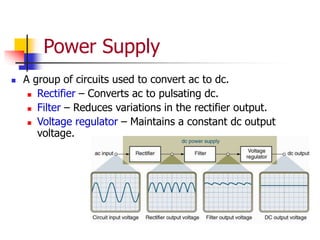
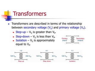
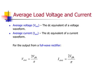
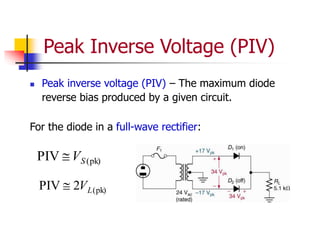
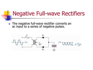
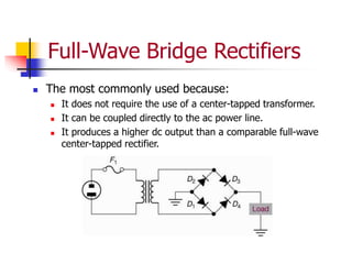
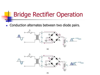
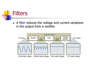
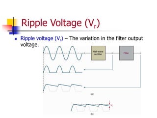
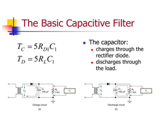
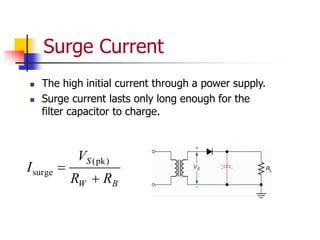
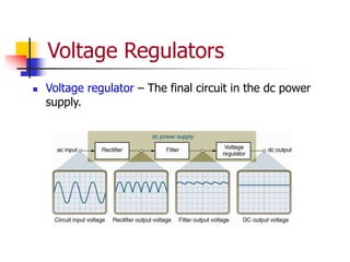
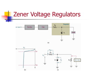
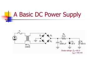
Chapter 3
Common Diode Applications
Basic Power Supply Circuits
Power Supply
 A group of circuits used to convert ac to dc.
 Rectifier – Converts ac to pulsating dc.
 Filter – Reduces variations in the rectifier output.
 Voltage regulator – Maintains a constant dc output
voltage.
Transformers
 Transformers are described in terms of the relationship
between secondary voltage (VS) and primary voltage (VP).
 Step-up – VS is greater than VP.
 Step-down – VS is less than VP.
 Isolation – VS is approximately
equal to VP.
Transformer Voltage and Current
Ratios
S
P
P
S
P
S
I
I
V
V
N
N


Half-wave Rectifiers
 Half-wave rectifier – A diode placed in series between
a transformer (or ac line input) and its load.
Positive Half-wave Rectifiers
This circuit converts an
ac input to a series of
positive pulses.
Average Load Voltage and Current
 Average voltage (Vave) – The dc equivalent of a
voltage waveform.
 Average current (Iave) – The dc equivalent of a
current waveform.
For the output from a half-wave rectifier:

pk
V
Vave 

pk
I
Iave 
Negative Half-wave Rectifiers
This circuit converts an
ac input to a series of
negative pulses.
Peak Inverse Voltage (PIV)
Peak inverse voltage (PIV) – The maximum diode
reverse bias produced by a given circuit.
For the diode in a half-wave rectifier:
(pk)
PIV S
V

Full-wave Rectifier
Full-wave Rectifier Operation
Diodes conduct during
alternate half cycles of
the input signal.
VL(pk) is approximately
half the value of VS(pk).
The circuit produces
two positive half-cycles
for each input cycle.
Average Load Voltage and Current
 Average voltage (Vave) – The dc equivalent of a voltage
waveform.
 Average current (Iave) – The dc equivalent of a current
waveform.
For the output from a full-wave rectifier:

pk
2V
Vave 

pk
2I
Iave 
Peak Inverse Voltage (PIV)
 Peak inverse voltage (PIV) – The maximum diode
reverse bias produced by a given circuit.
For the diode in a full-wave rectifier:
(pk)
PIV S
V

(pk)
2
PIV L
V

Negative Full-wave Rectifiers
 The negative full-wave rectifier converts an
ac input to a series of negative pulses.
Full-Wave Bridge Rectifiers
 The most commonly used because:
 It does not require the use of a center-tapped transformer.
 It can be coupled directly to the ac power line.
 It produces a higher dc output than a comparable full-wave
center-tapped rectifier.
Bridge Rectifier Operation
 Conduction alternates between two diode pairs.
Calculating load voltage and
current relationships
V
7
.
0
PIV
π
2
V
4
.
1
S(pk)
ave
ave
)
(pk
ave
(pk)
)
(pk






V
R
V
I
V
V
V
V
L
L
S
L
Working with Rectifiers
 Rectifiers are high current circuits, so IFRB can have a
significant impact on diode forward voltage (VF ).
 Cooling is often used to minimize the effects of high
power rectifier reverse current. Components may be
cooled using a fan and/or a heat sink.
 High transformer tolerances can introduce significant
discrepancies between calculated and measured
current and voltage values.
Integrated Rectifiers
 Integrated Rectifier – A rectifier circuit that is etched
on a single piece of silicon (housed in a single case).
IC rectifiers are:
 Cheaper to produce
 Easier to troubleshoot
 The diodes in an IC rectifier operate at the same
temperature, so they have equal values of forward
voltage and leakage current.
 IC rectifier cases are designed to be attached easily
to a heat sink.
Filters
 A filter reduces the voltage and current variations
in the output from a rectifier.
Ripple Voltage (Vr)
 Ripple voltage (Vr) – The variation in the filter output
voltage.
The Basic Capacitive Filter
 The capacitor:
 charges through the
rectifier diode.
 discharges through
the load.
1
1
1
5
5
C
R
T
C
R
T
L
D
D
C


Surge Current
 The high initial current through a power supply.
 Surge current lasts only long enough for the
filter capacitor to charge.
B
W
S
R
R
V
I


)
pk
(
surge
Limiting Surge Current
Surge current can be limited by:
 Inserting a current limiting resistor between the filter
capacitor and the rectifier.
 Using a low-value filter capacitor (which shortens the
duration of the surge).
 Using an inductive filter.
Filter output voltages
C
t
I
V
V
V
V
L
r
r



2
pk
dc
Filtering and Half-wave
Rectifier PIV
)
pk
(
2
PIV S
V

LC Filters
Voltage Regulators
 Voltage regulator – The final circuit in the dc power
supply.
Zener Voltage Regulators
Regulator Response to
Load Variations
Zener Reduction of Vr
r
S
L
Z
L
Z
r V
R
R
Z
R
Z
V


)
||
(
||
(out)
A Basic DC Power Supply

Diodes.ppt

  • 1.
    Chapter 3 Common DiodeApplications Basic Power Supply Circuits
  • 2.
    Power Supply  Agroup of circuits used to convert ac to dc.  Rectifier – Converts ac to pulsating dc.  Filter – Reduces variations in the rectifier output.  Voltage regulator – Maintains a constant dc output voltage.
  • 3.
    Transformers  Transformers aredescribed in terms of the relationship between secondary voltage (VS) and primary voltage (VP).  Step-up – VS is greater than VP.  Step-down – VS is less than VP.  Isolation – VS is approximately equal to VP.
  • 4.
    Transformer Voltage andCurrent Ratios S P P S P S I I V V N N  
  • 5.
    Half-wave Rectifiers  Half-waverectifier – A diode placed in series between a transformer (or ac line input) and its load.
  • 6.
    Positive Half-wave Rectifiers Thiscircuit converts an ac input to a series of positive pulses.
  • 7.
    Average Load Voltageand Current  Average voltage (Vave) – The dc equivalent of a voltage waveform.  Average current (Iave) – The dc equivalent of a current waveform. For the output from a half-wave rectifier:  pk V Vave   pk I Iave 
  • 8.
    Negative Half-wave Rectifiers Thiscircuit converts an ac input to a series of negative pulses.
  • 9.
    Peak Inverse Voltage(PIV) Peak inverse voltage (PIV) – The maximum diode reverse bias produced by a given circuit. For the diode in a half-wave rectifier: (pk) PIV S V 
  • 10.
  • 11.
    Full-wave Rectifier Operation Diodesconduct during alternate half cycles of the input signal. VL(pk) is approximately half the value of VS(pk). The circuit produces two positive half-cycles for each input cycle.
  • 12.
    Average Load Voltageand Current  Average voltage (Vave) – The dc equivalent of a voltage waveform.  Average current (Iave) – The dc equivalent of a current waveform. For the output from a full-wave rectifier:  pk 2V Vave   pk 2I Iave 
  • 13.
    Peak Inverse Voltage(PIV)  Peak inverse voltage (PIV) – The maximum diode reverse bias produced by a given circuit. For the diode in a full-wave rectifier: (pk) PIV S V  (pk) 2 PIV L V 
  • 14.
    Negative Full-wave Rectifiers The negative full-wave rectifier converts an ac input to a series of negative pulses.
  • 15.
    Full-Wave Bridge Rectifiers The most commonly used because:  It does not require the use of a center-tapped transformer.  It can be coupled directly to the ac power line.  It produces a higher dc output than a comparable full-wave center-tapped rectifier.
  • 16.
    Bridge Rectifier Operation Conduction alternates between two diode pairs.
  • 17.
    Calculating load voltageand current relationships V 7 . 0 PIV π 2 V 4 . 1 S(pk) ave ave ) (pk ave (pk) ) (pk       V R V I V V V V L L S L
  • 18.
    Working with Rectifiers Rectifiers are high current circuits, so IFRB can have a significant impact on diode forward voltage (VF ).  Cooling is often used to minimize the effects of high power rectifier reverse current. Components may be cooled using a fan and/or a heat sink.  High transformer tolerances can introduce significant discrepancies between calculated and measured current and voltage values.
  • 19.
    Integrated Rectifiers  IntegratedRectifier – A rectifier circuit that is etched on a single piece of silicon (housed in a single case). IC rectifiers are:  Cheaper to produce  Easier to troubleshoot  The diodes in an IC rectifier operate at the same temperature, so they have equal values of forward voltage and leakage current.  IC rectifier cases are designed to be attached easily to a heat sink.
  • 20.
    Filters  A filterreduces the voltage and current variations in the output from a rectifier.
  • 21.
    Ripple Voltage (Vr) Ripple voltage (Vr) – The variation in the filter output voltage.
  • 22.
    The Basic CapacitiveFilter  The capacitor:  charges through the rectifier diode.  discharges through the load. 1 1 1 5 5 C R T C R T L D D C  
  • 23.
    Surge Current  Thehigh initial current through a power supply.  Surge current lasts only long enough for the filter capacitor to charge. B W S R R V I   ) pk ( surge
  • 24.
    Limiting Surge Current Surgecurrent can be limited by:  Inserting a current limiting resistor between the filter capacitor and the rectifier.  Using a low-value filter capacitor (which shortens the duration of the surge).  Using an inductive filter.
  • 25.
  • 26.
    Filtering and Half-wave RectifierPIV ) pk ( 2 PIV S V 
  • 27.
  • 28.
    Voltage Regulators  Voltageregulator – The final circuit in the dc power supply.
  • 29.
  • 30.
  • 31.
    Zener Reduction ofVr r S L Z L Z r V R R Z R Z V   ) || ( || (out)
  • 32.
    A Basic DCPower Supply