Downloaded 356 times
![Standard Test Signals
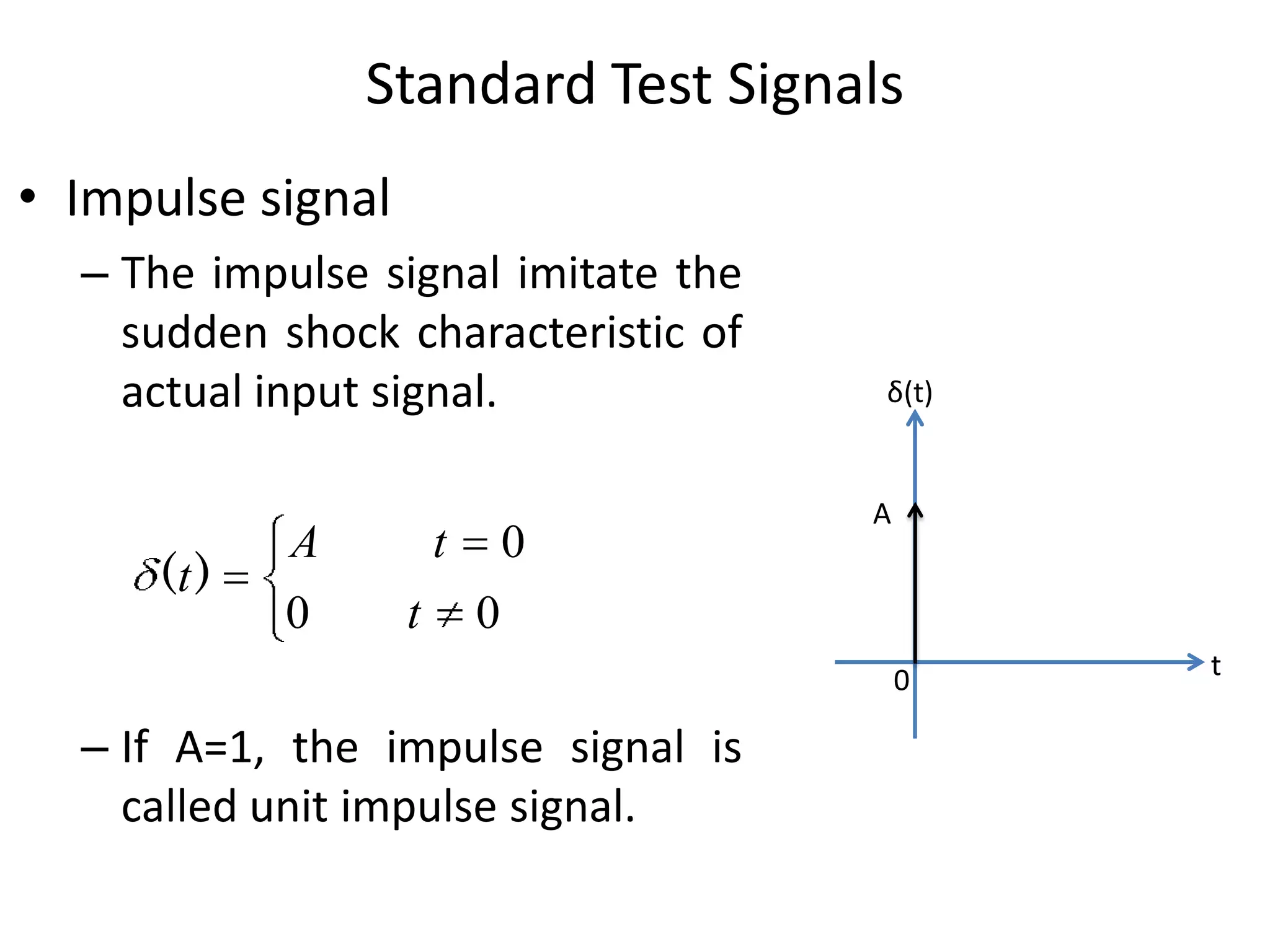
• Impulse signal
Source: English Wikipedia. Iain. Original image: [1]](https://image.slidesharecdn.com/lecture12timedomainanalysisofcontrolsystems-140304142057-phpapp02/75/Lecture-12-time_domain_analysis_of_control_systems-5-2048.jpg)
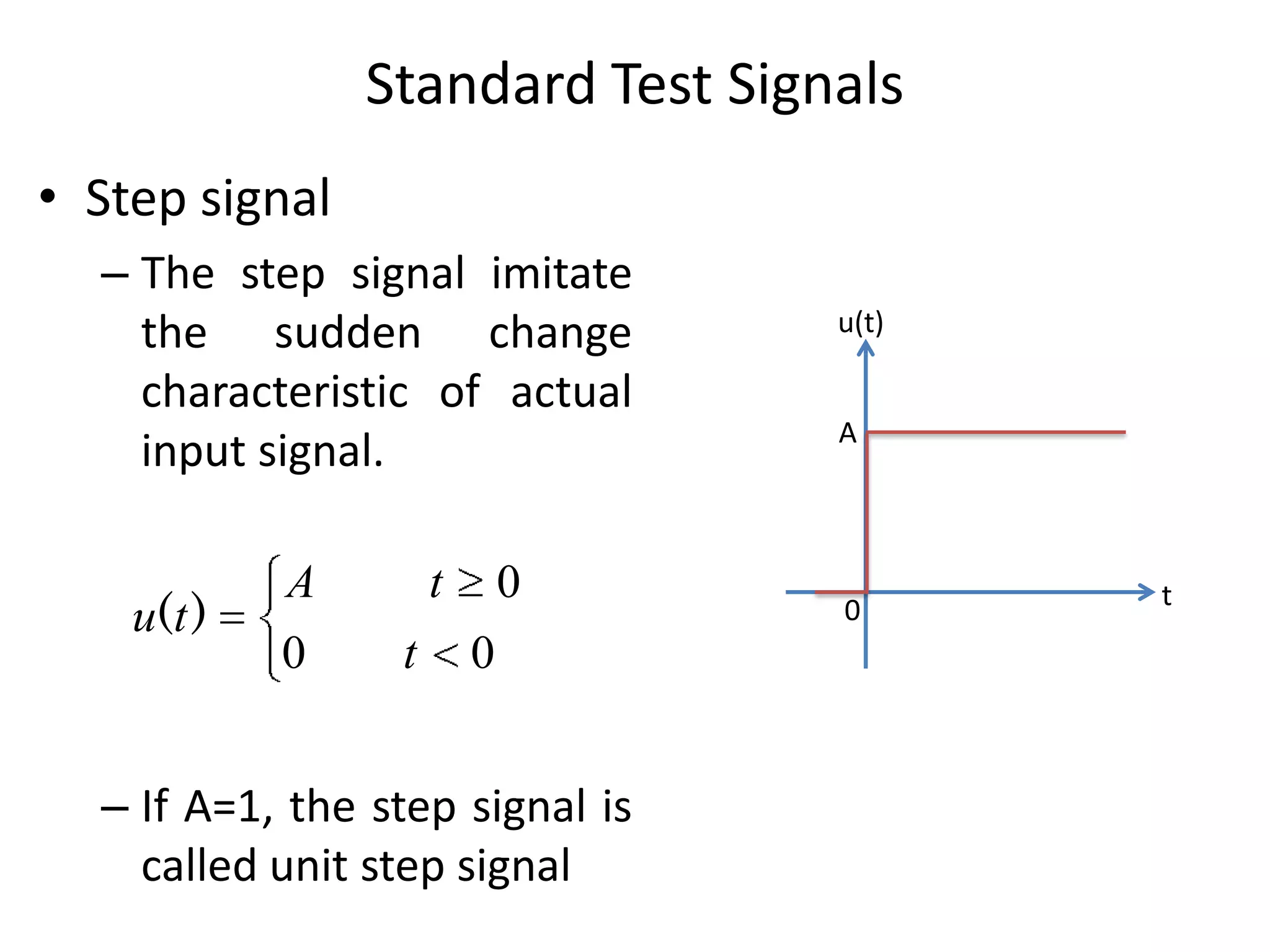
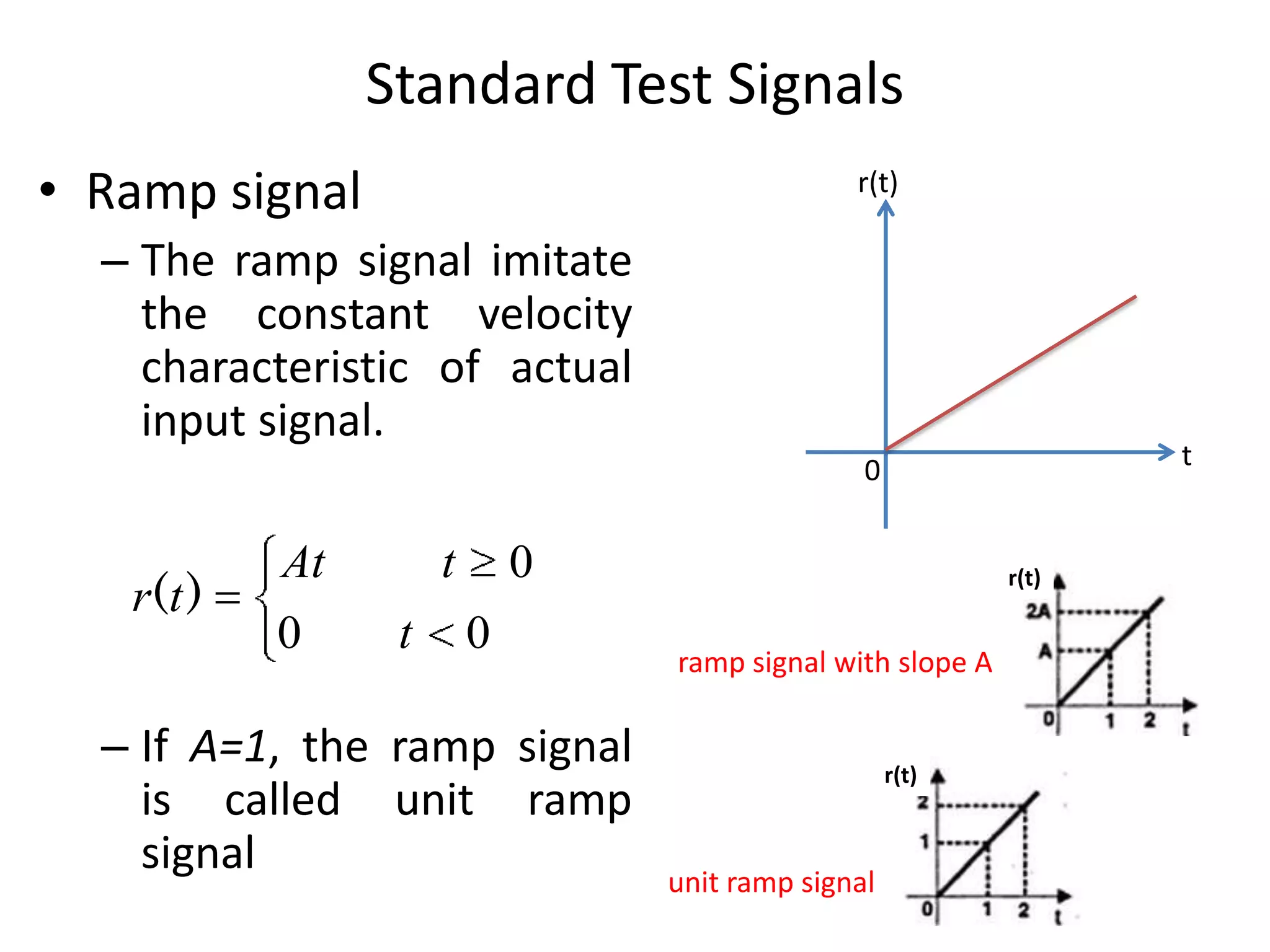
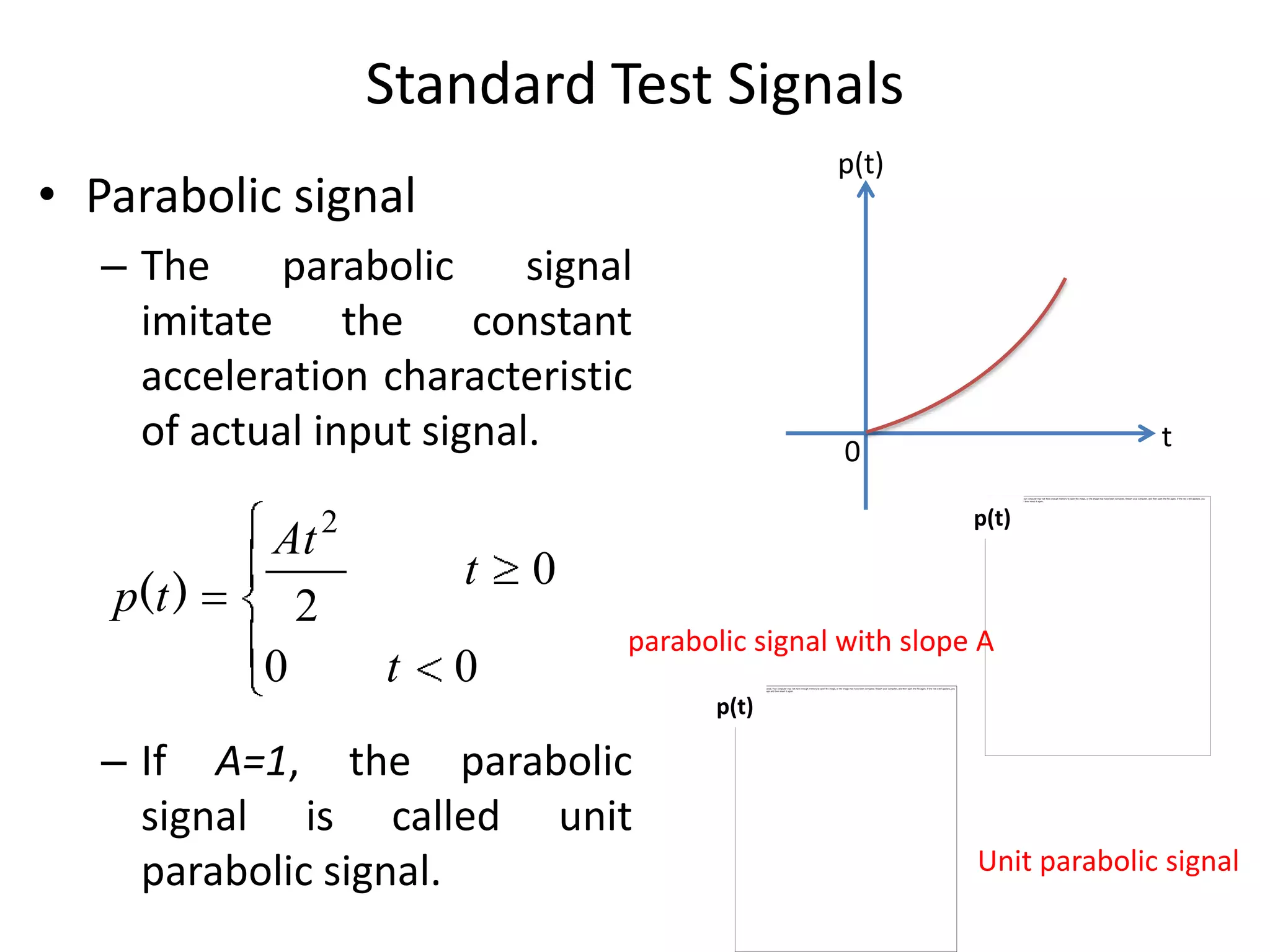
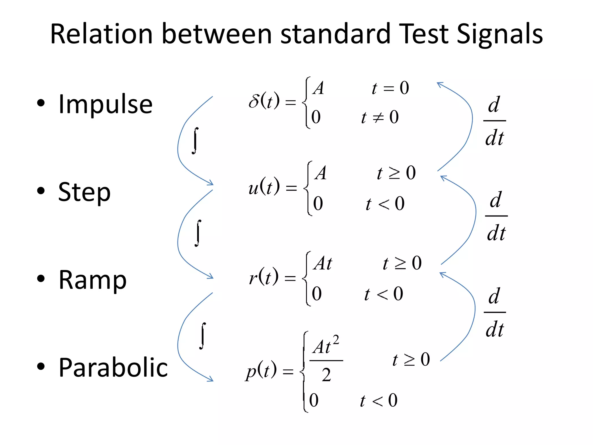
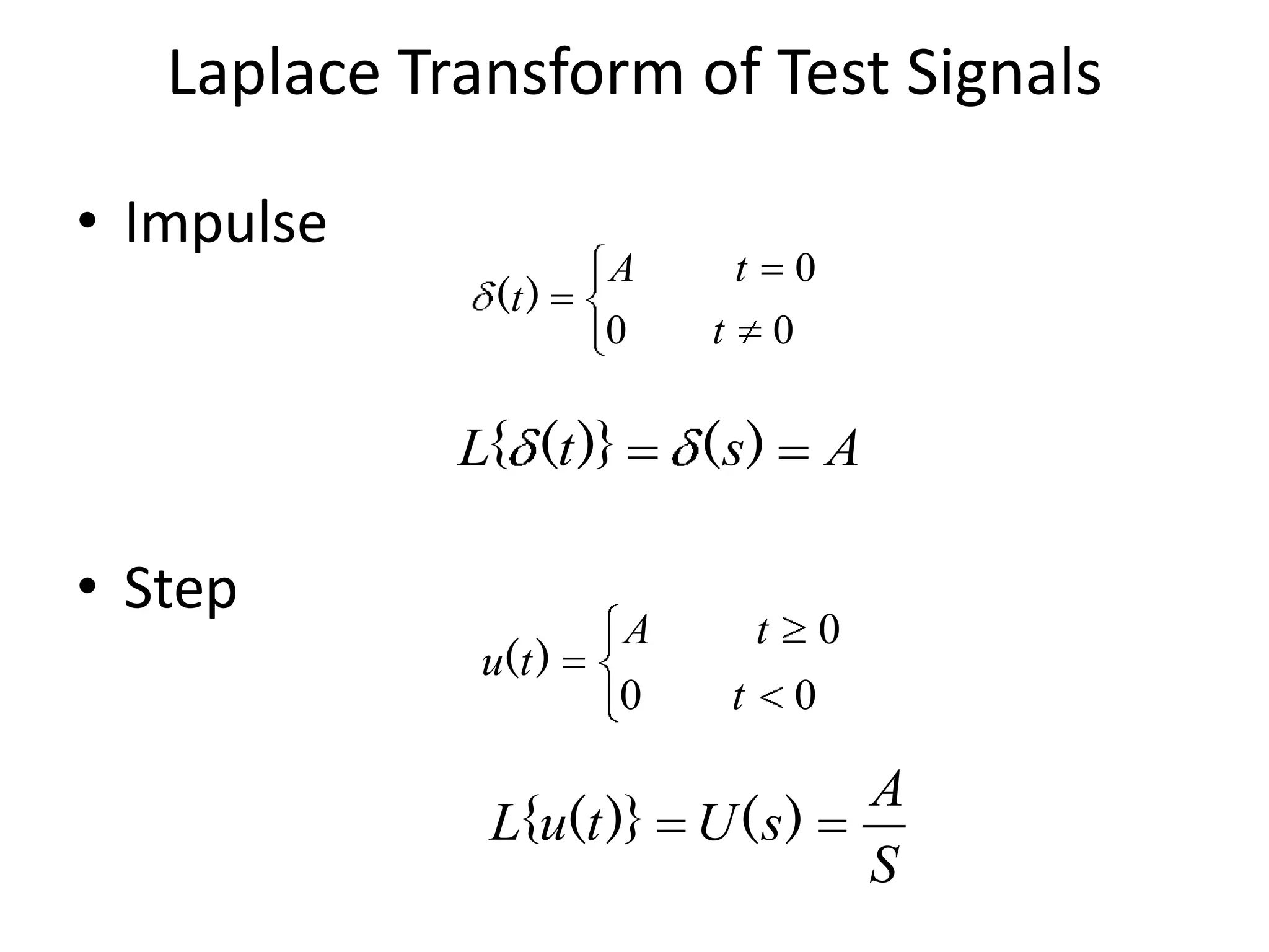
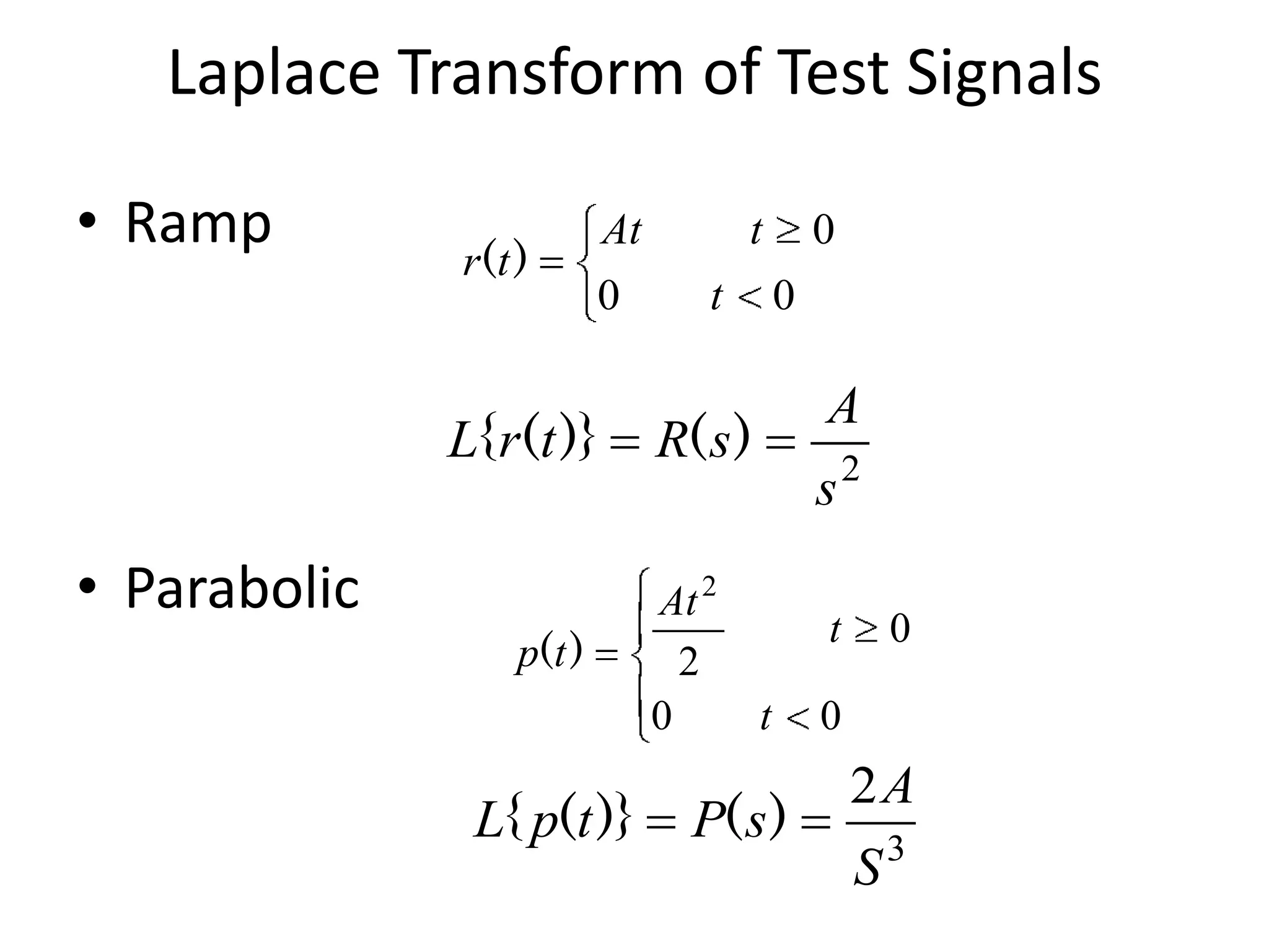
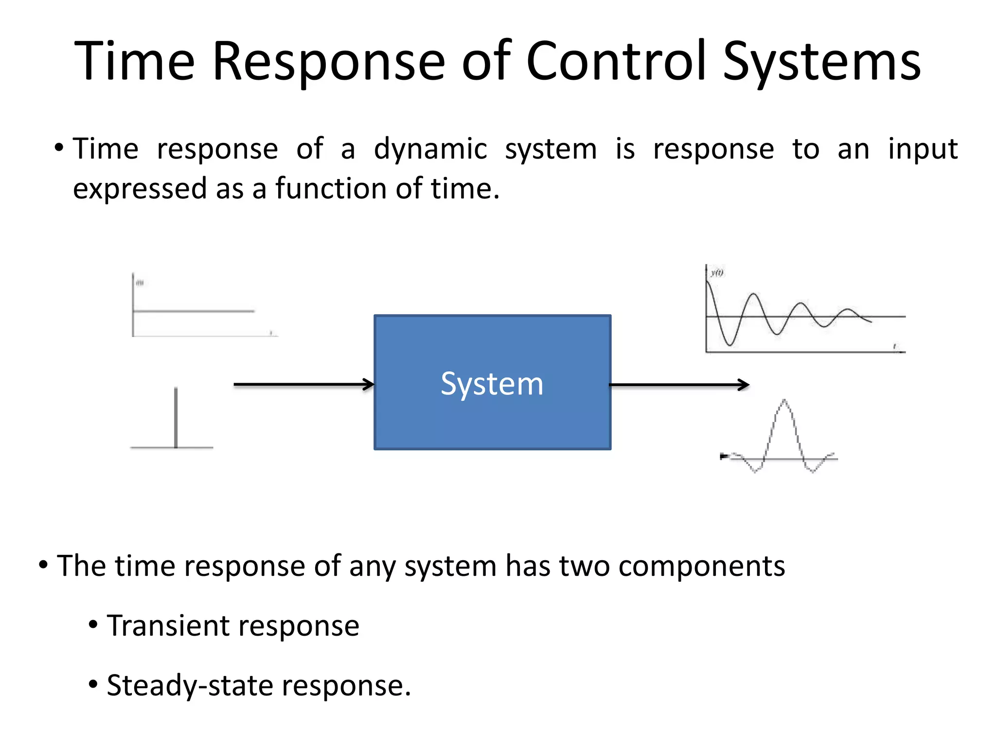
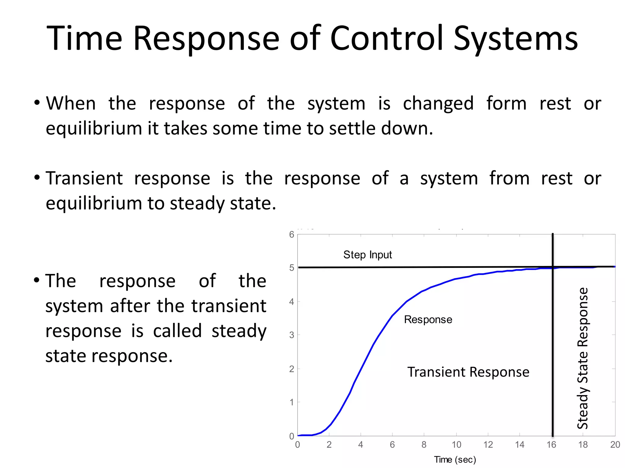


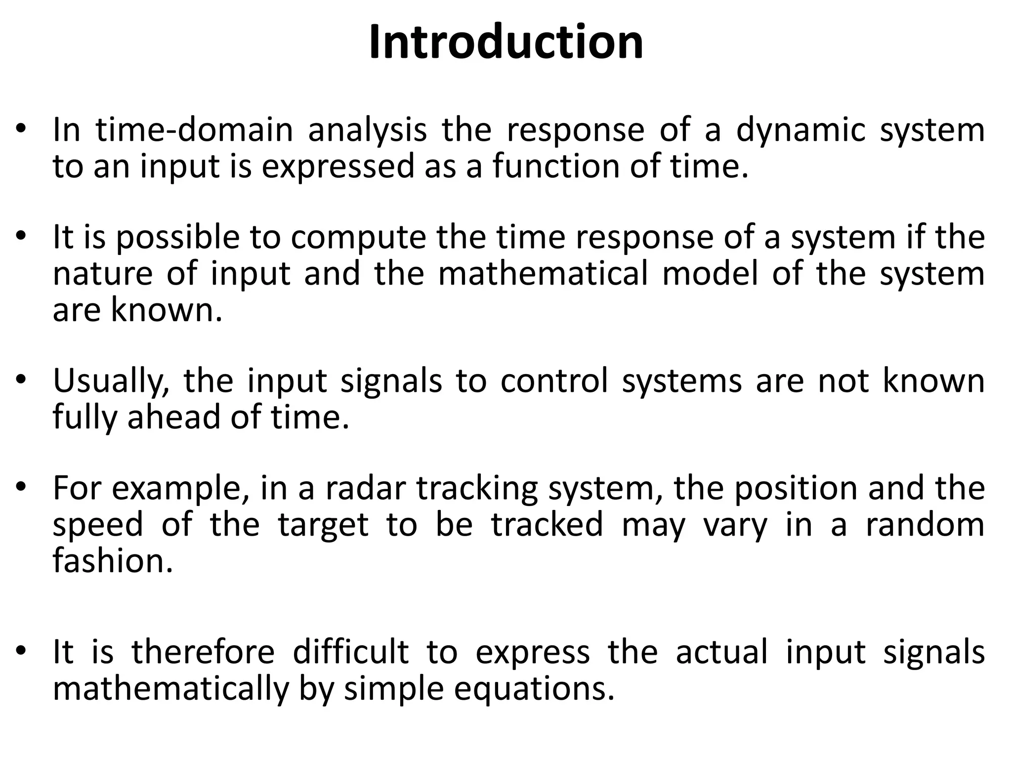
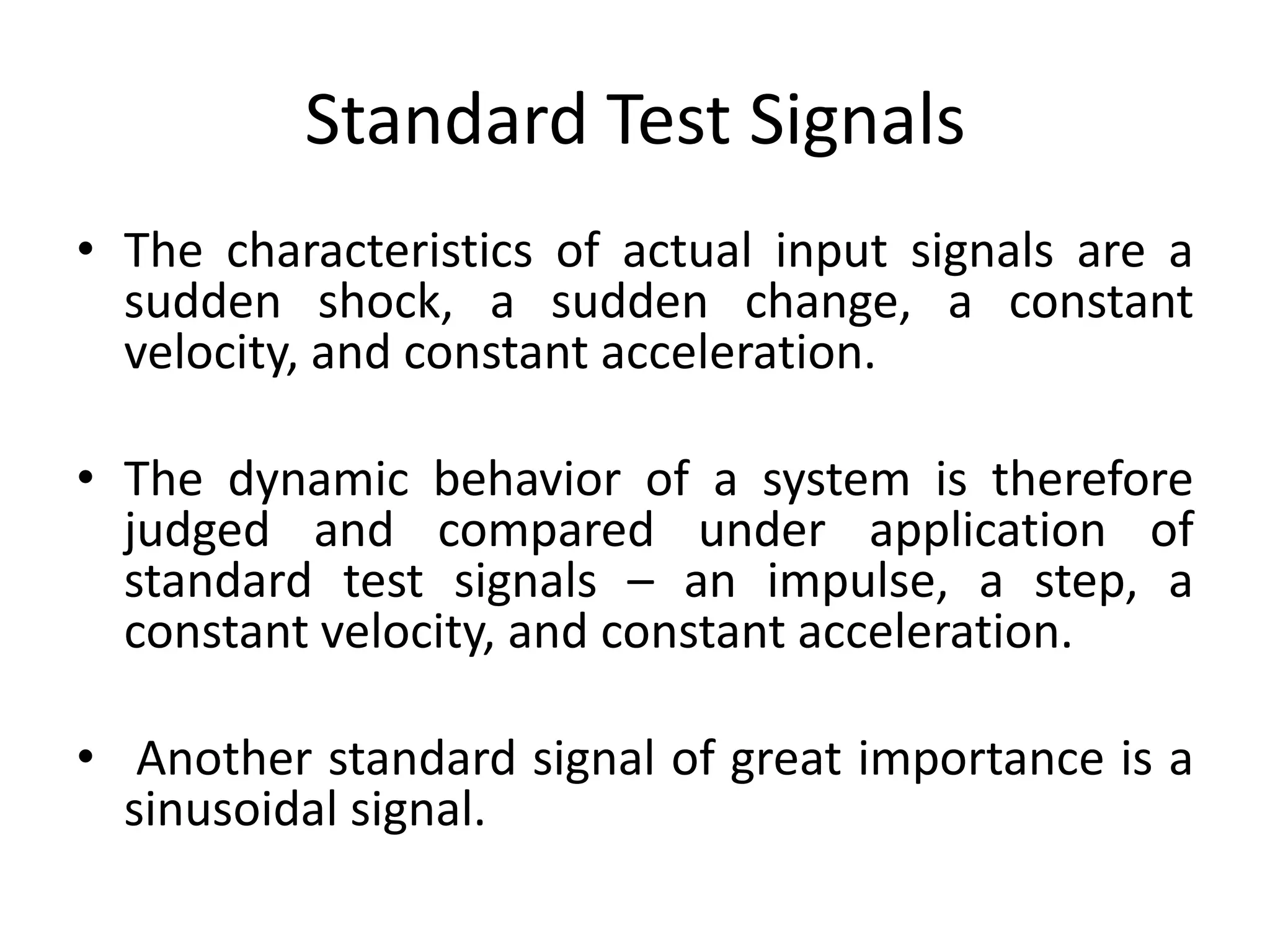
This document discusses time domain analysis of control systems. It introduces standard test signals used to analyze dynamic systems, including impulse, step, ramp, and parabolic signals. These signals mimic characteristics of actual inputs like sudden shock, changes, constant velocity, and acceleration. The time response of a system has two components - transient response as it moves from rest to steady state, and steady-state response once settled. Standard signals are used to examine a system's transient response and steady-state response depends on both system dynamics and input type.