Downloaded 1,220 times


The document provides a comprehensive overview of lathe machines, detailing their history, working principles, and various classifications such as speed lathes, engine lathes, and automatic lathes. It also covers the construction and parts of a lathe, its specifications, and the different operations that can be performed, such as turning, drilling, and threading. Additionally, it discusses work-holding devices commonly used with lathe machines.
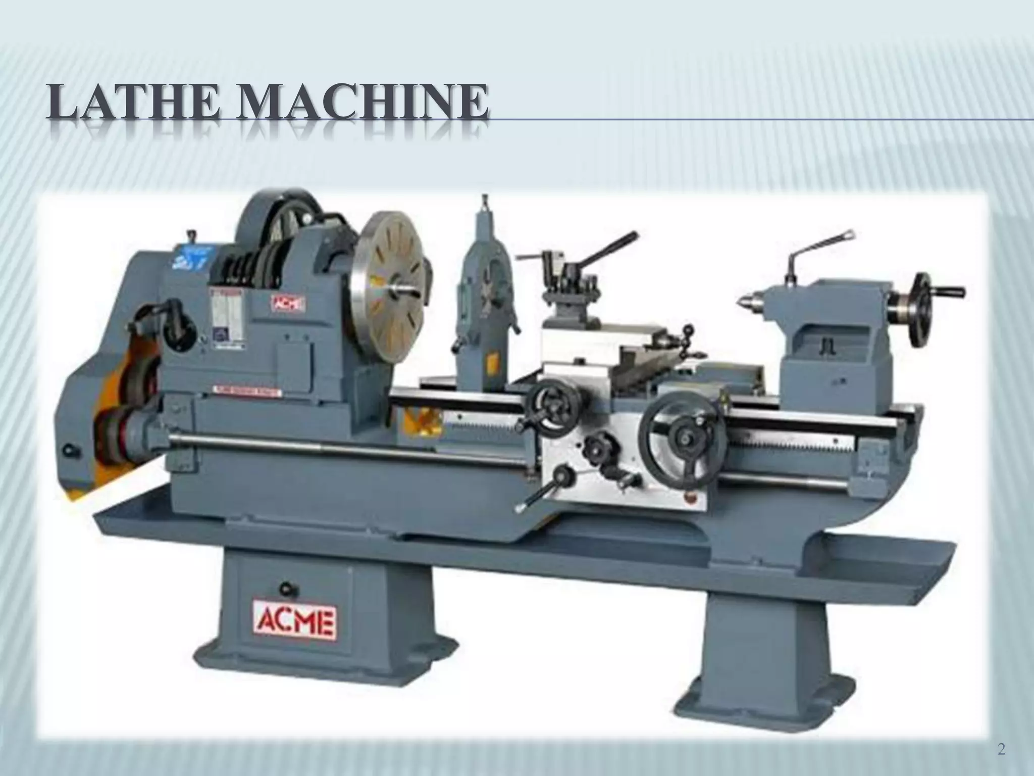
Introduction to the presentation on manufacturing process focusing on lathe machinery.
Introduction to the lathe machine, a pivotal tool in metalworking.
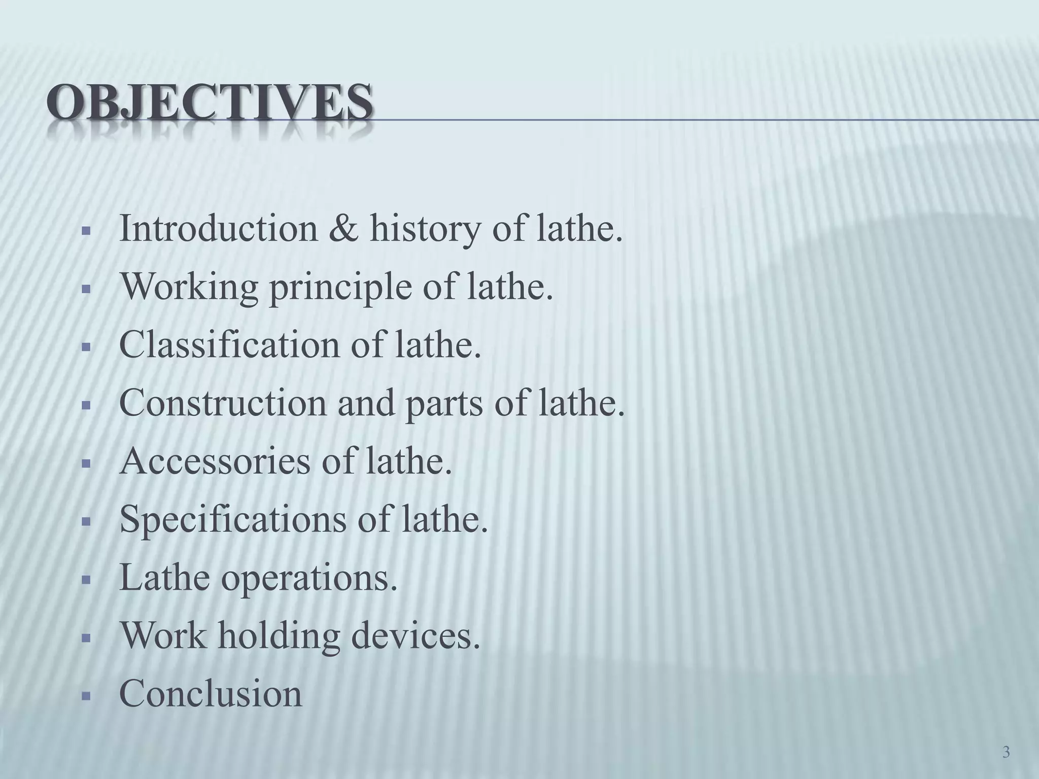
Key objectives of lathe operations, including history, classification, and parts.
A detailed explanation of the lathe as a critical machine tool used since the 1569 for metalwork.
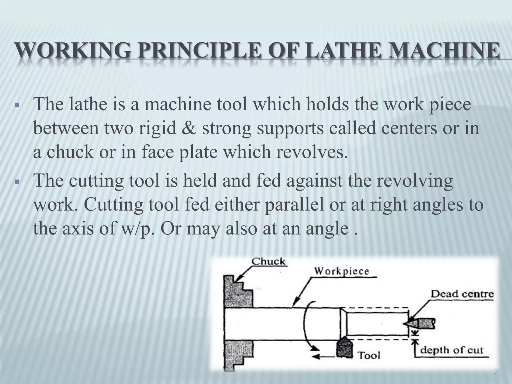
Explanation of the lathe's functional mechanism involving rotating work pieces and cutting tools.
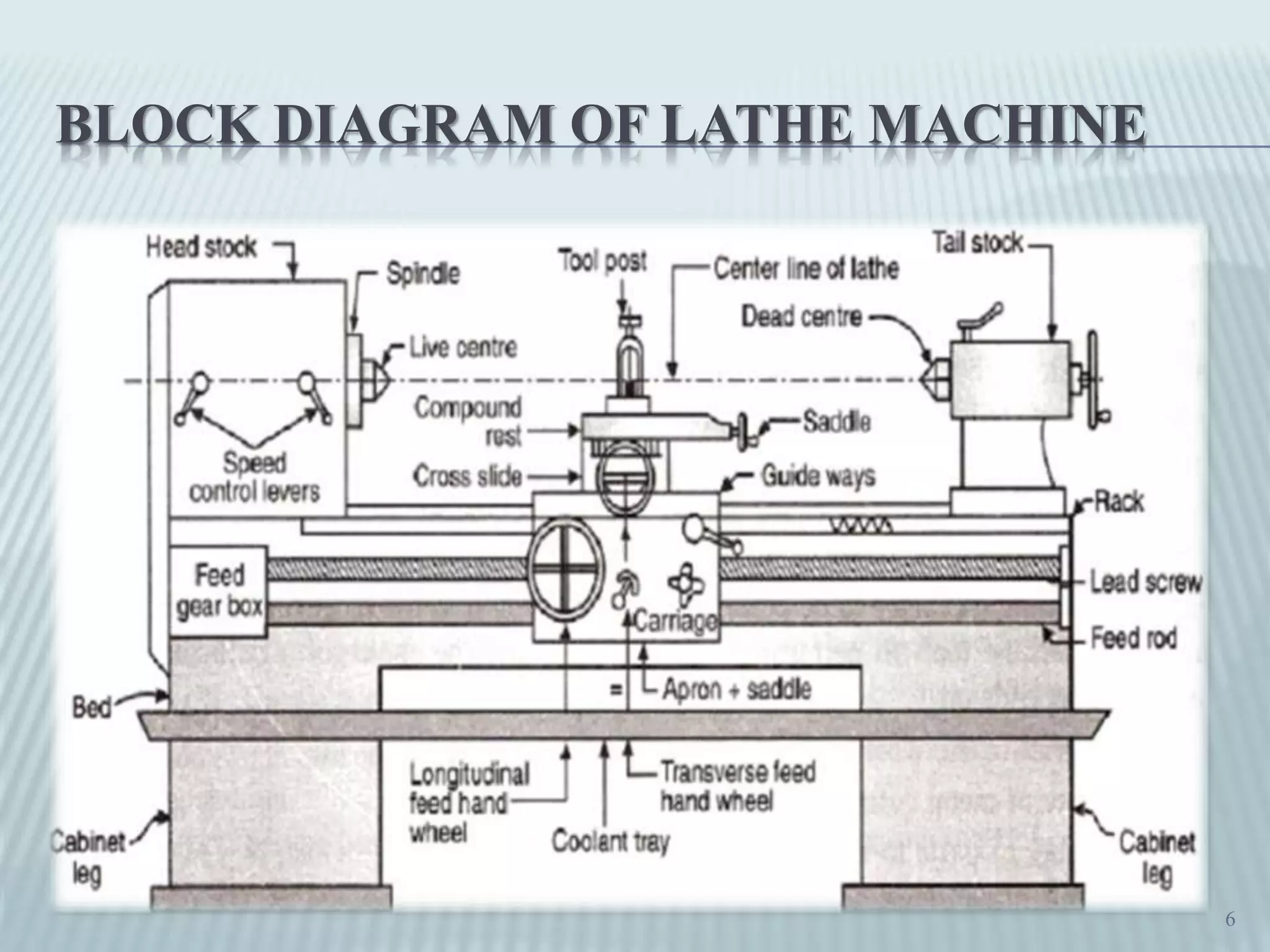
A block diagram illustrating the structure and operational layout of lathe machines.
Different types of lathe machines categorized based on their functionalities and use cases.
Description of speed lathes known for high spindle speeds between 1200 to 3600 rpm.
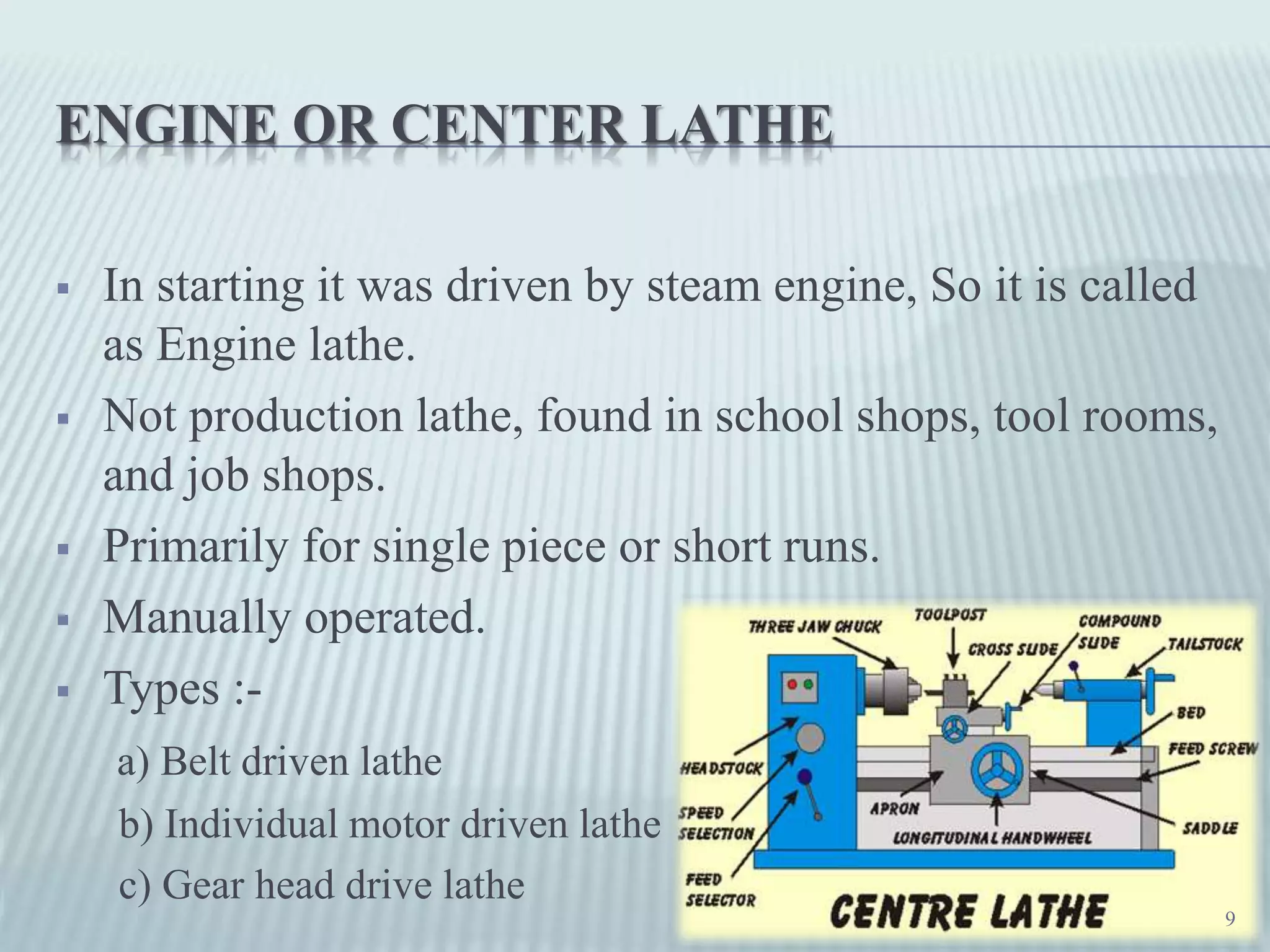
Overview of engine lathe operations and types, primarily for education and short runs.
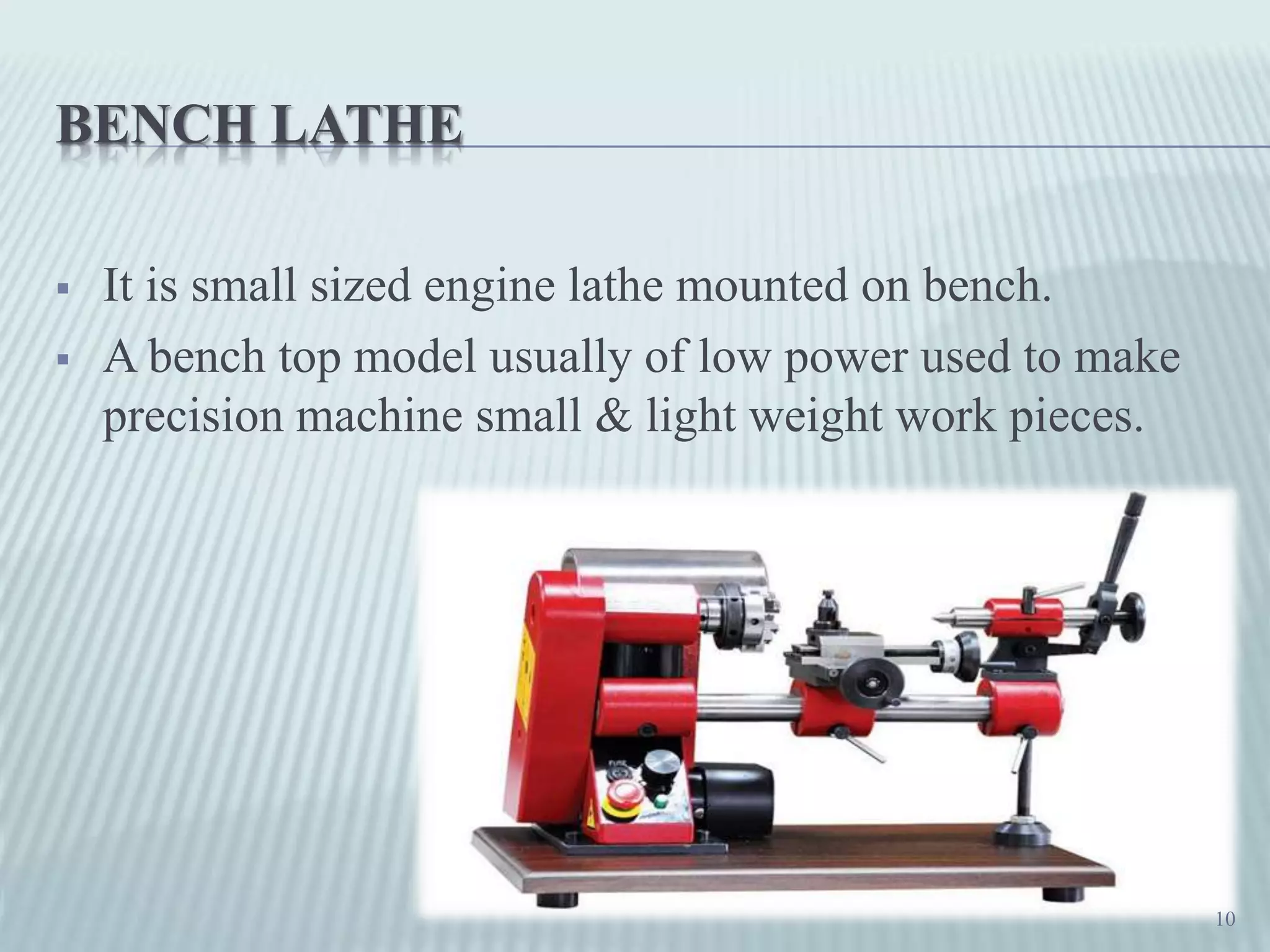
Bench lathes are small, precision machines designed for lightweight work pieces.
Tool room lathes used for high precision production tasks within workshops.
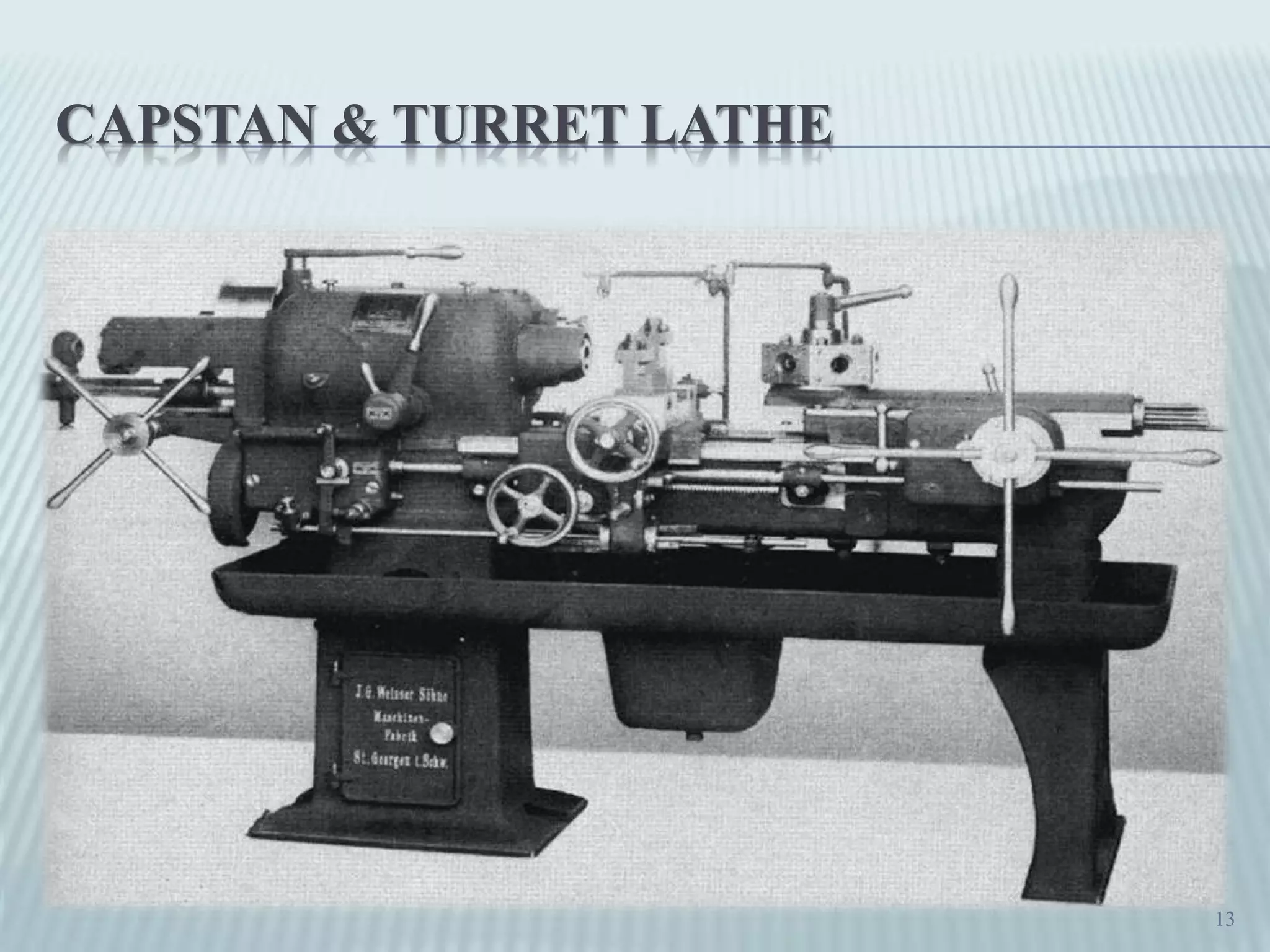
Distinction between capstan lathes for light work and turret lathes for heavy-duty tasks.
Further details on functionalities and advantages of Capstan and Turret lathes.
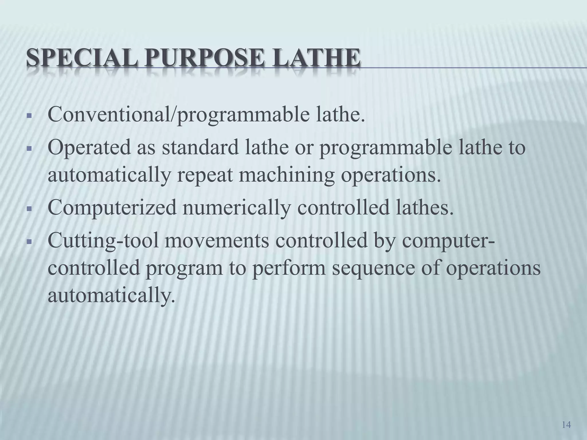
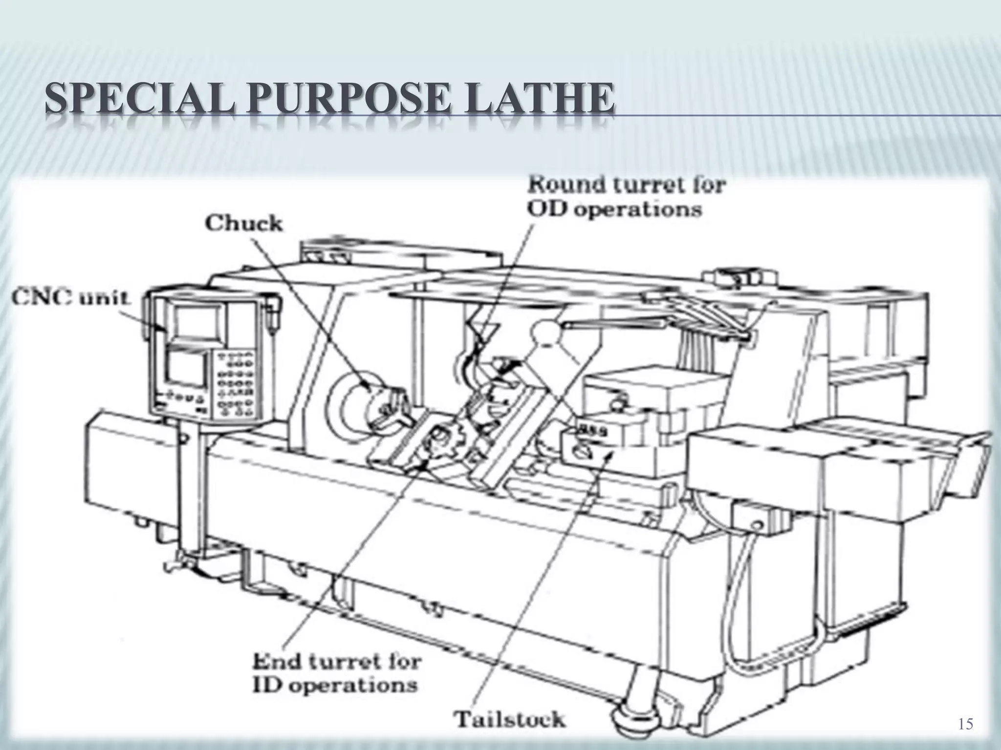
Description of programmable lathes capable of automated machining operations.
Additional insights into the functionalities of computerized numerically controlled lathes.
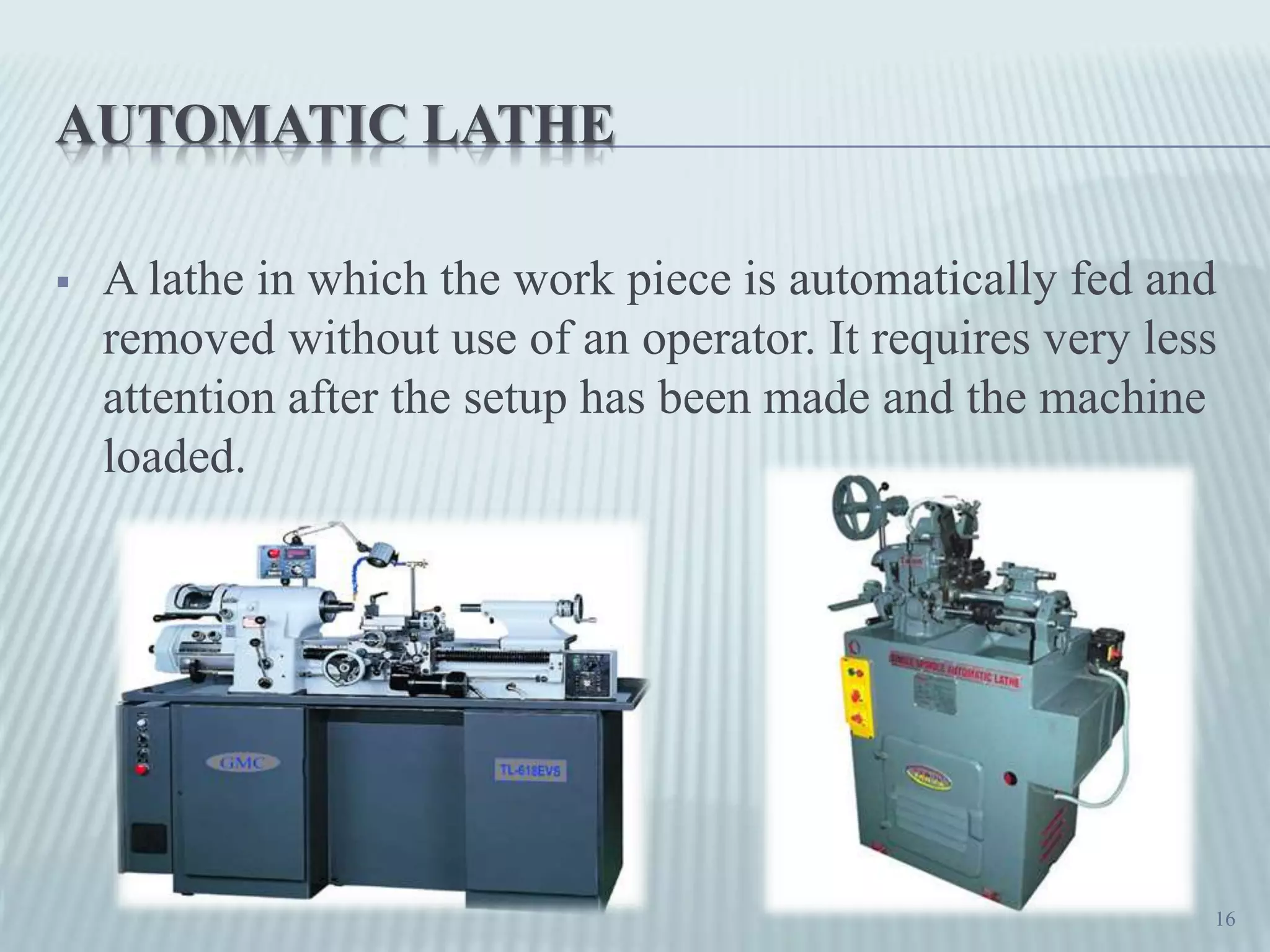
Overview of automatic lathes designed to minimize operator intervention during operation.
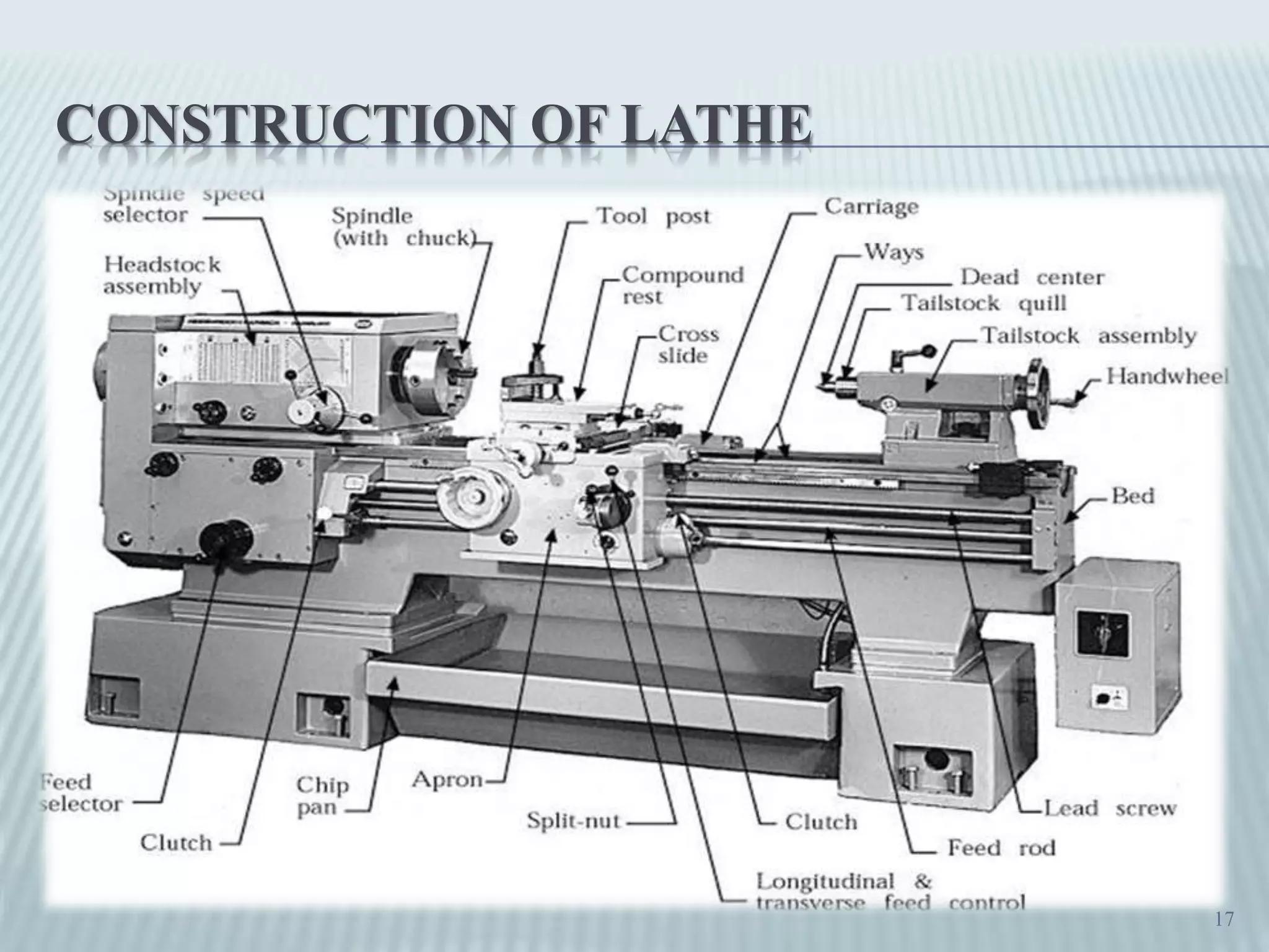
Discussion on the structural components and design of lathe machines.
Main components of a lathe including the bed, head stock, tail stock, and carriage.
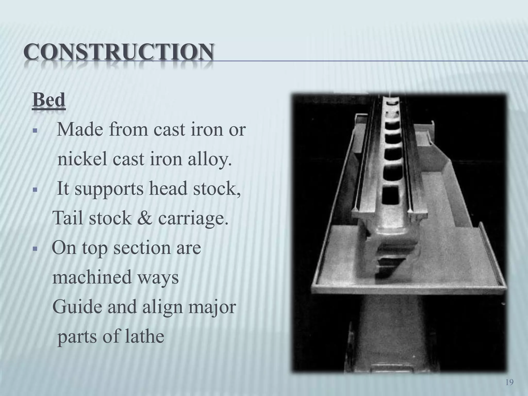
Detailed construction of the lathe bed, essential for support and alignment.
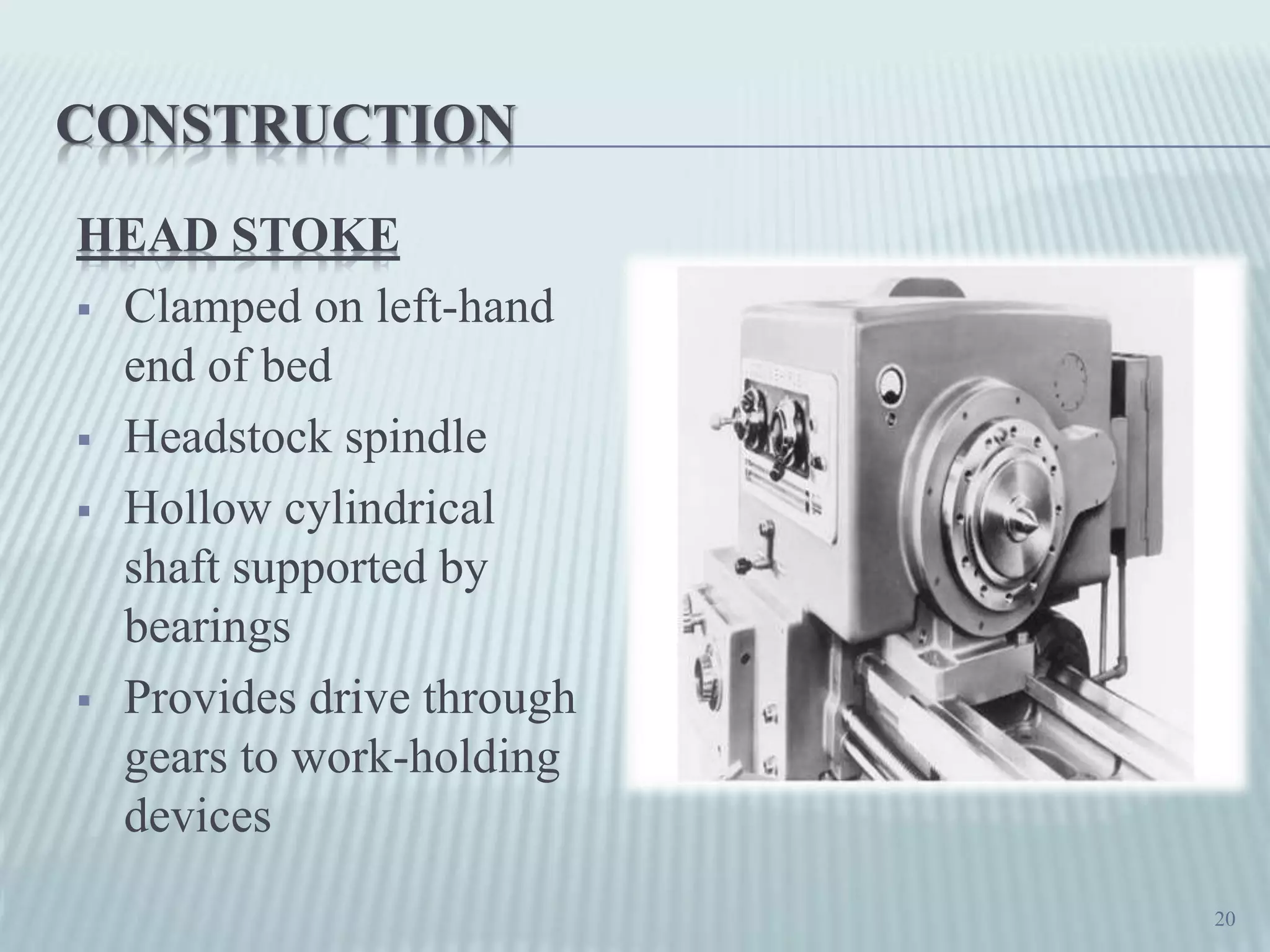
Functionality of the headstock, including drive mechanisms for work-holding devices.
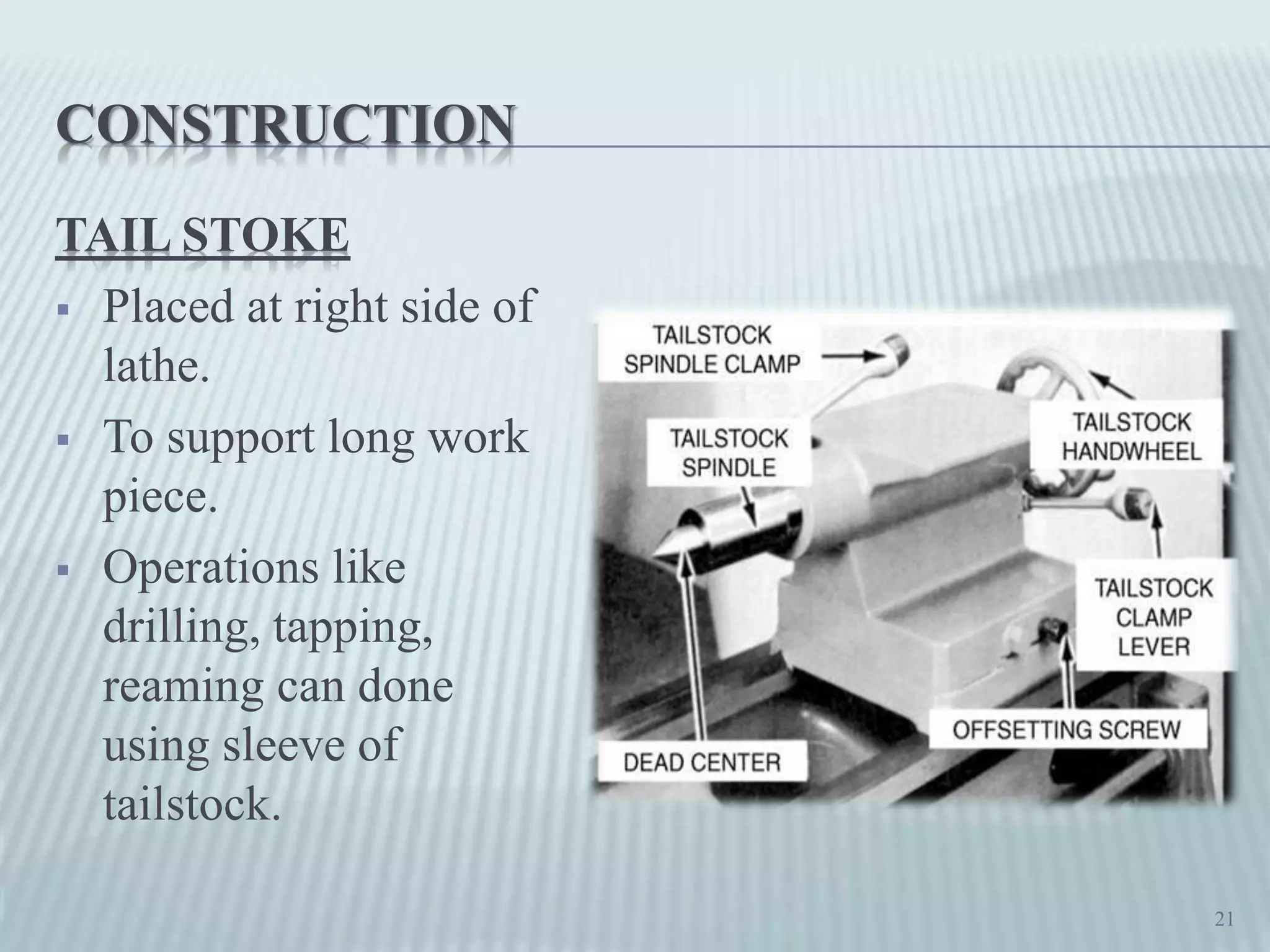
Explanation on how the tail stock supports long workpieces and additional operations.
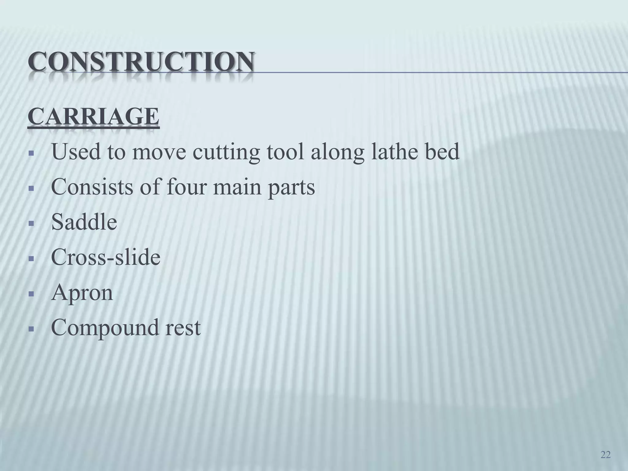
Mechanism of the carriage in guiding cutting tools along the lathe bed.
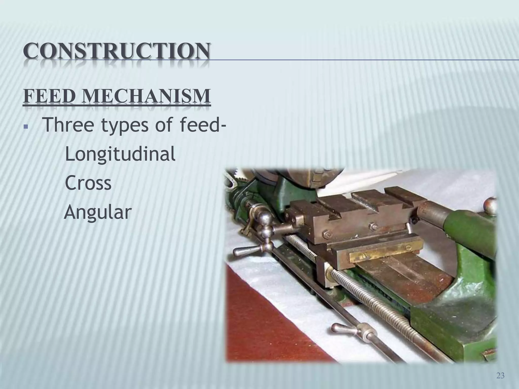
Three types of feeds used in a lathe: longitudinal, cross, and angular feeds.
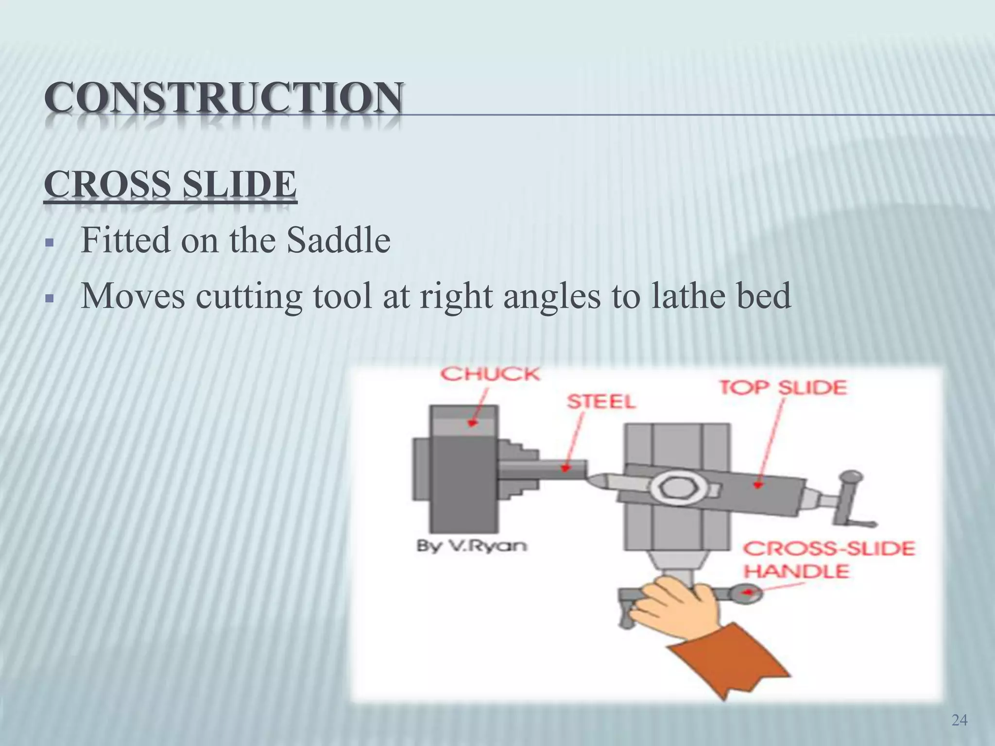
Details on the cross slide, enabling tool movement at right angles.
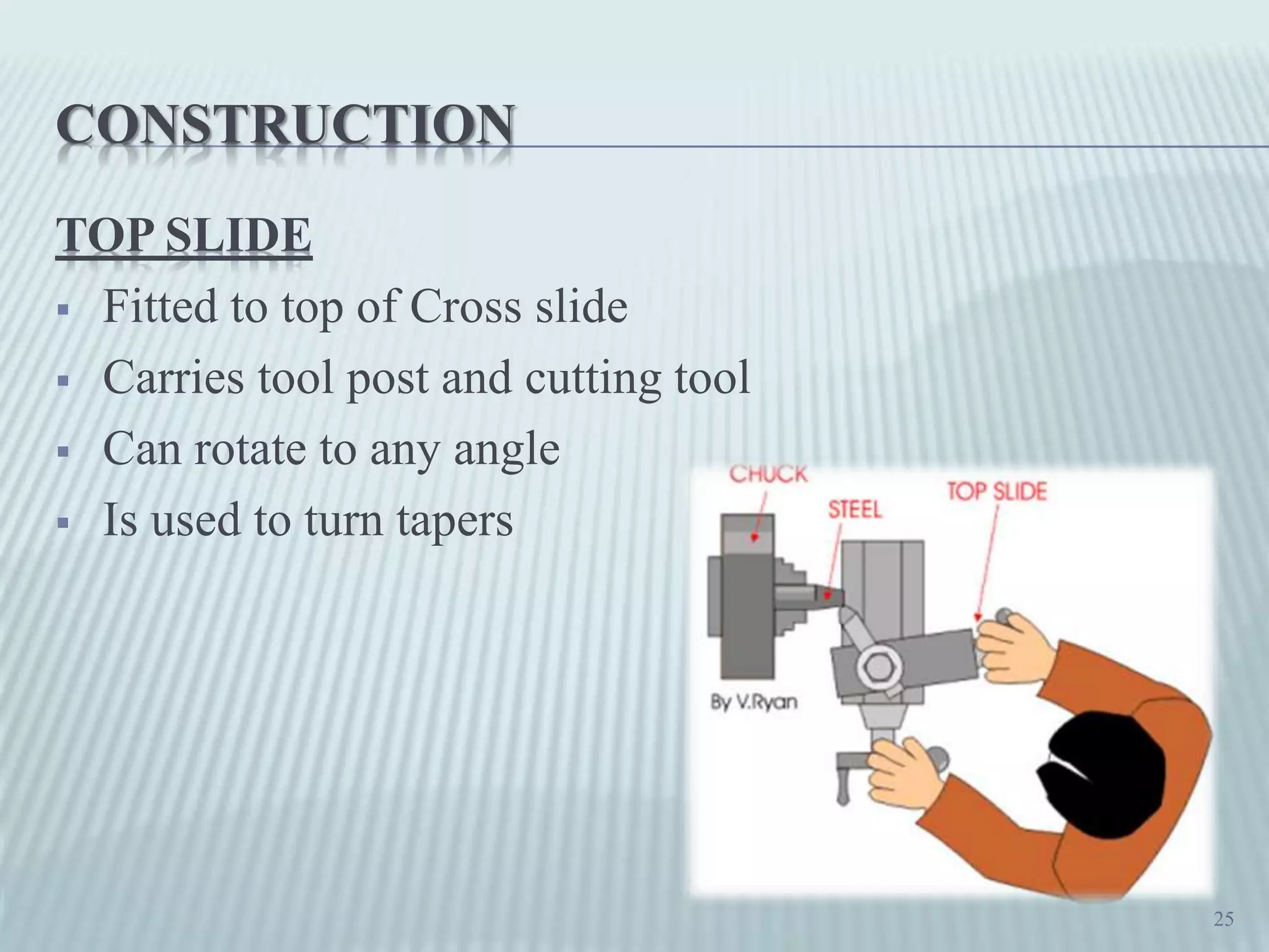
Description of the top slide's capability to adjust angles for taper turning.
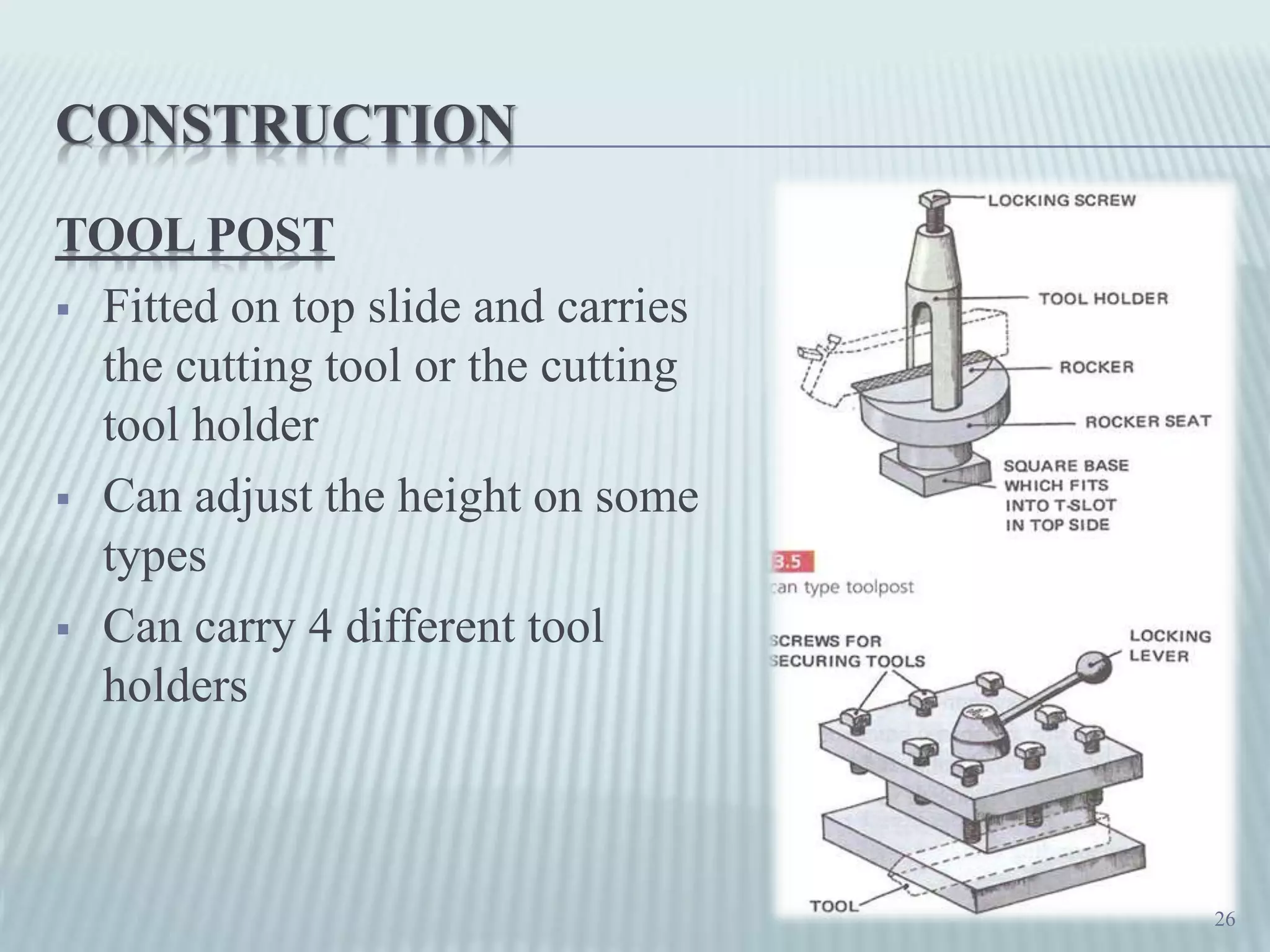
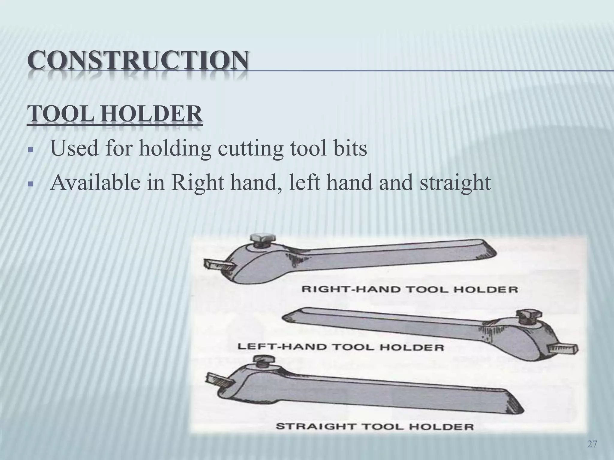
Information about the tool post, which holds cutting tools in place.
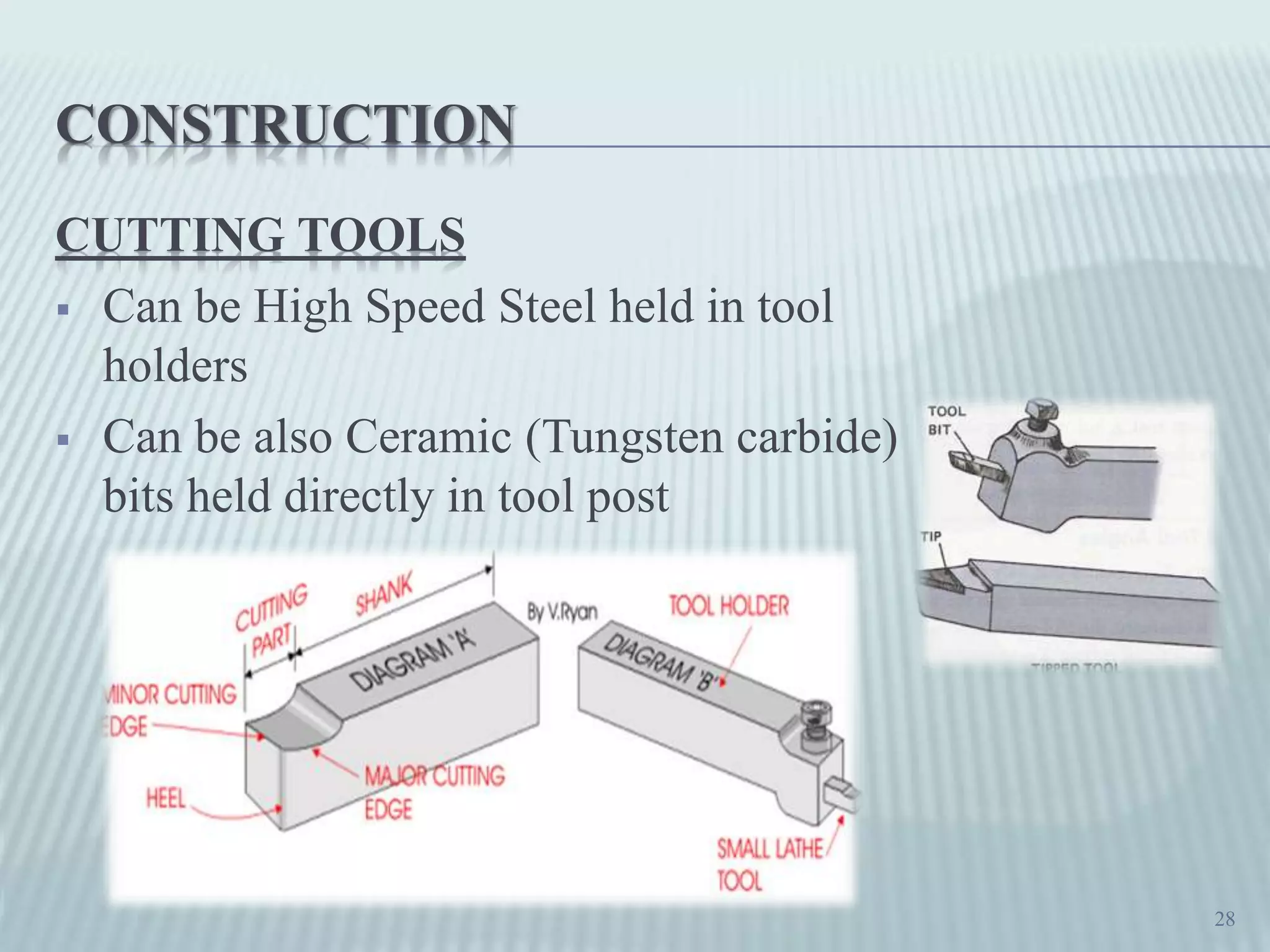
Types and functions of cutting tools used in lathe operations.
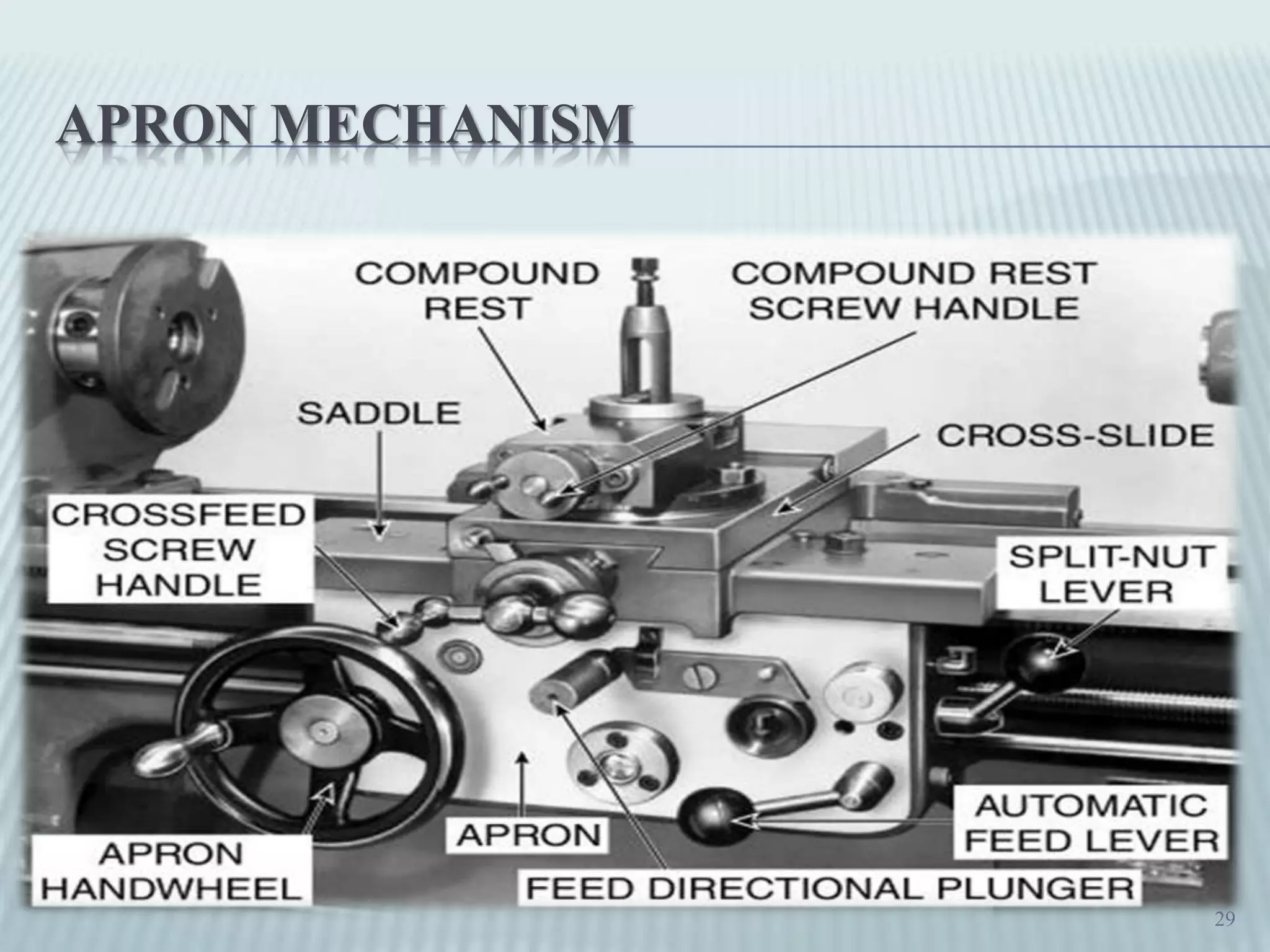
Brief mention of the apron mechanism essential for various lathe functions.
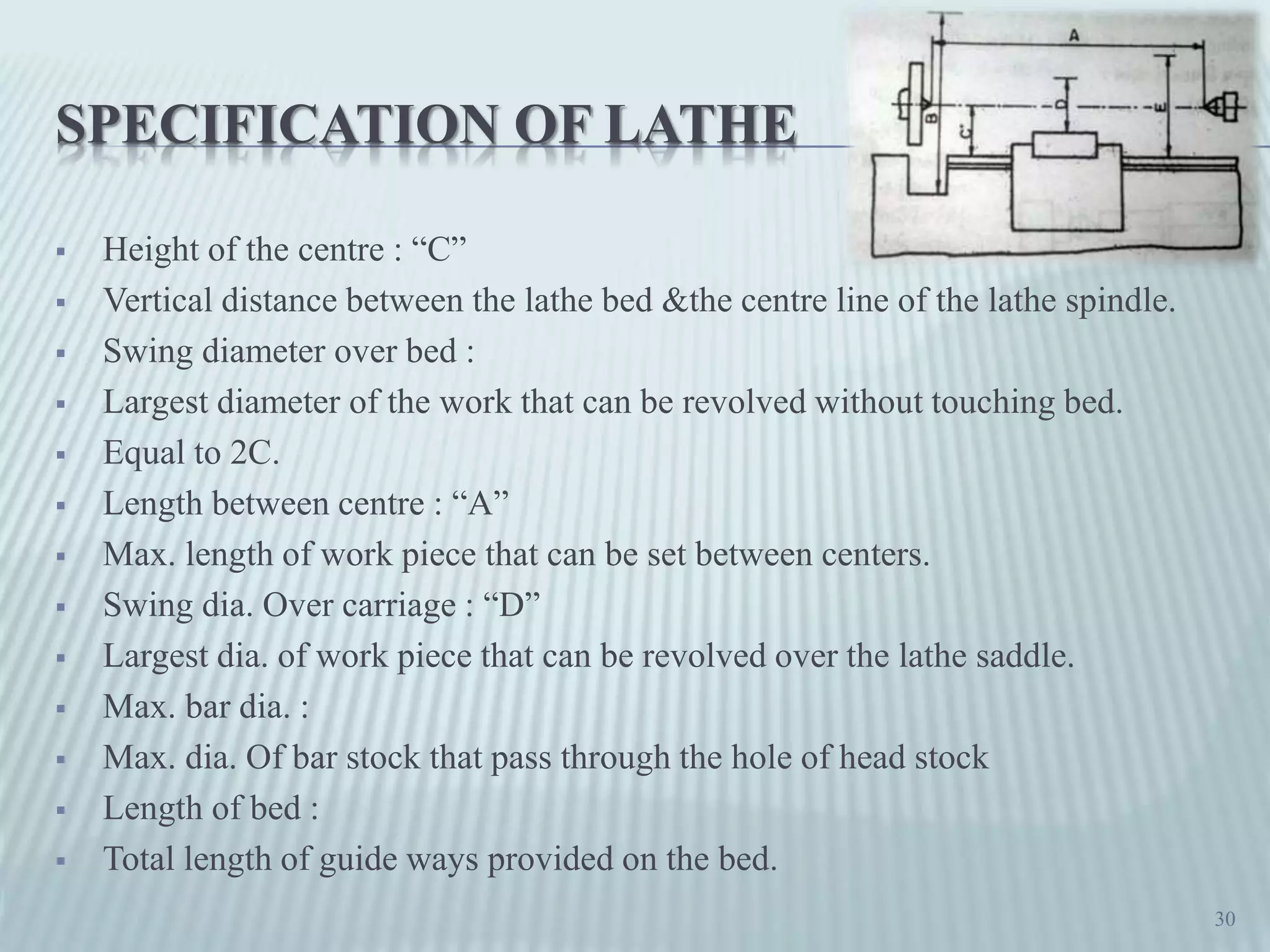
Key specifications of lathe machines like the height of the center and swing diameter.
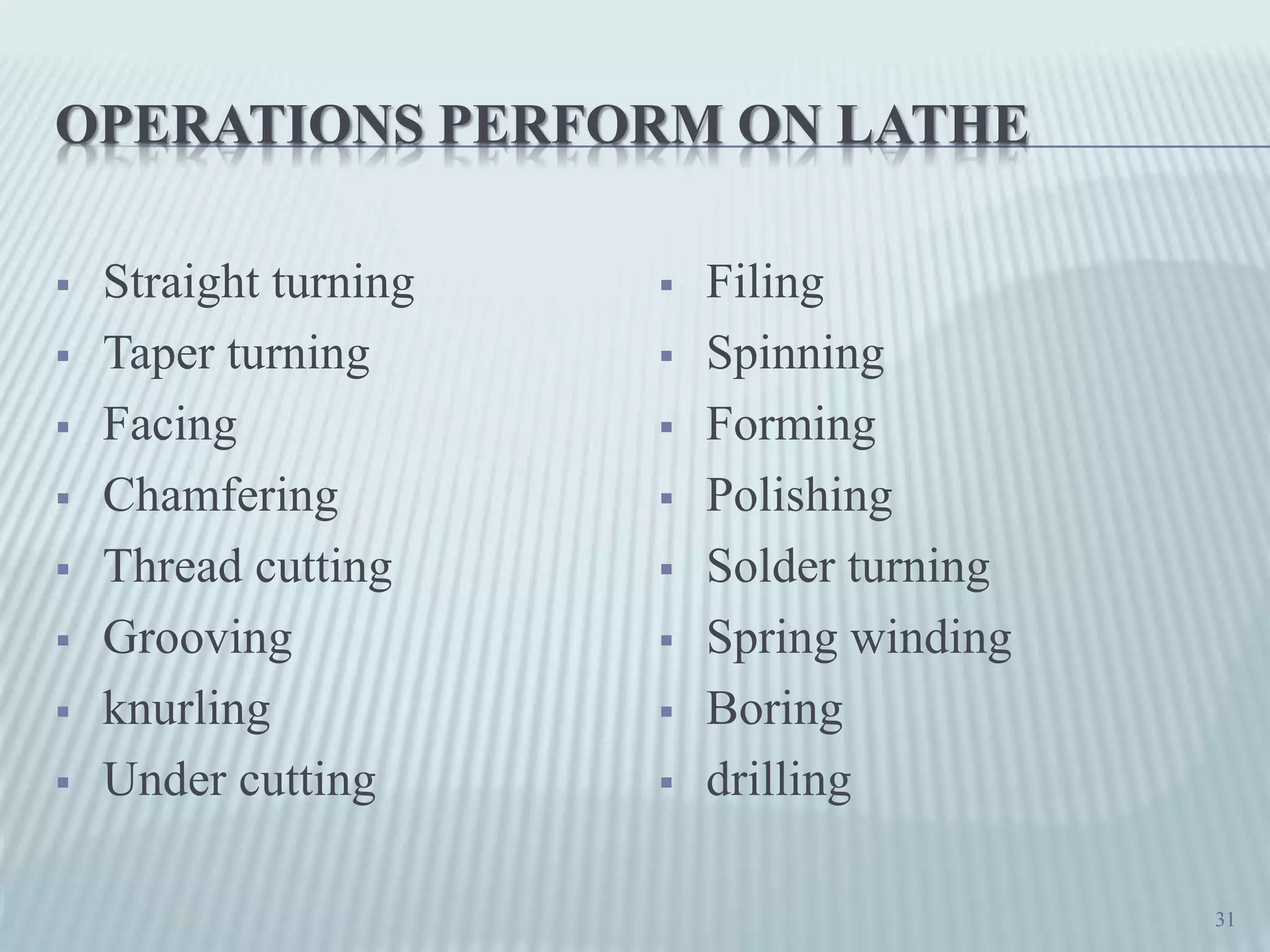
Comprehensive list of various operations performed on lathes, including turning and boring.
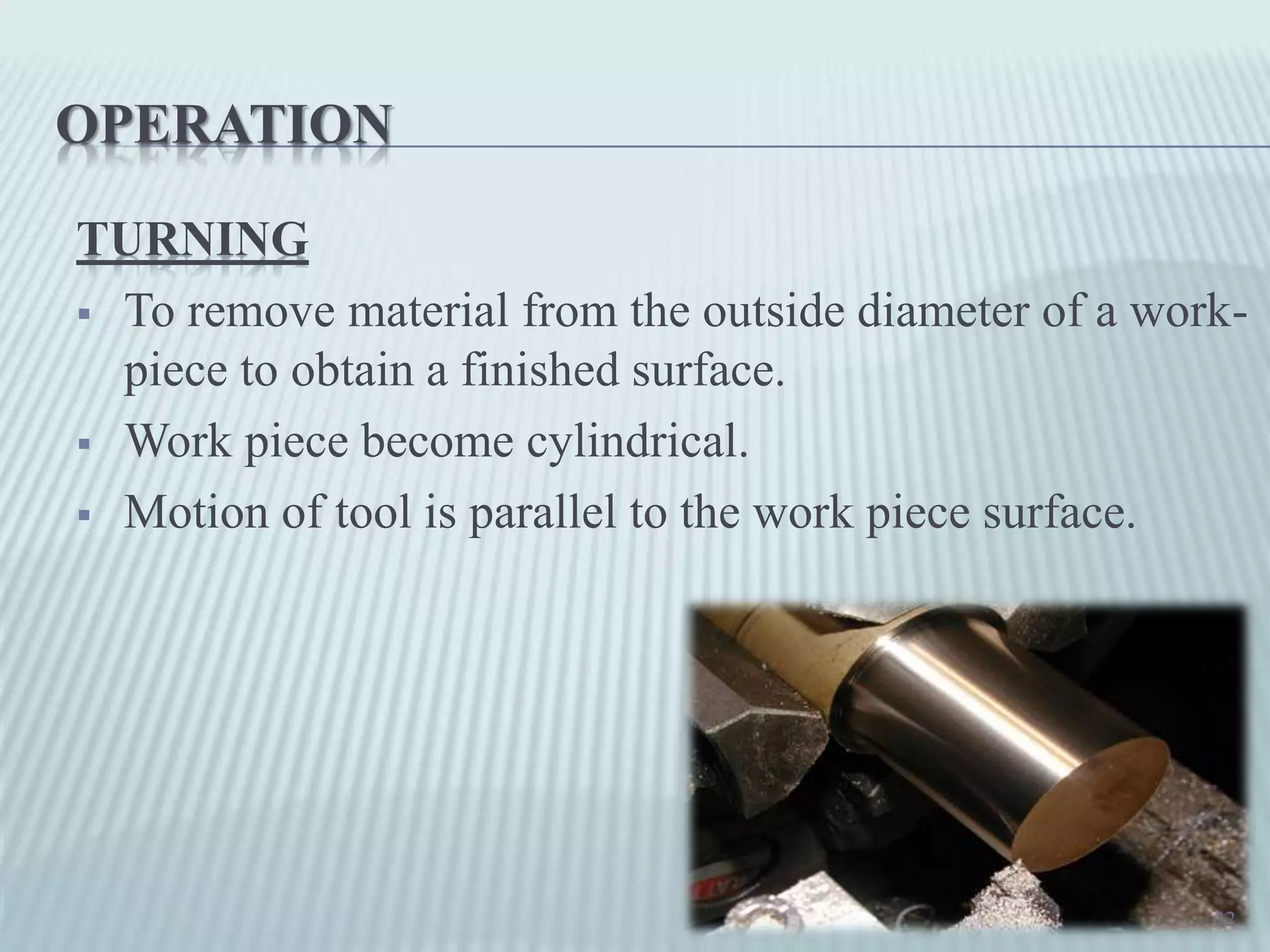
Description of straight turning, aimed at achieving a cylindrical workpiece.
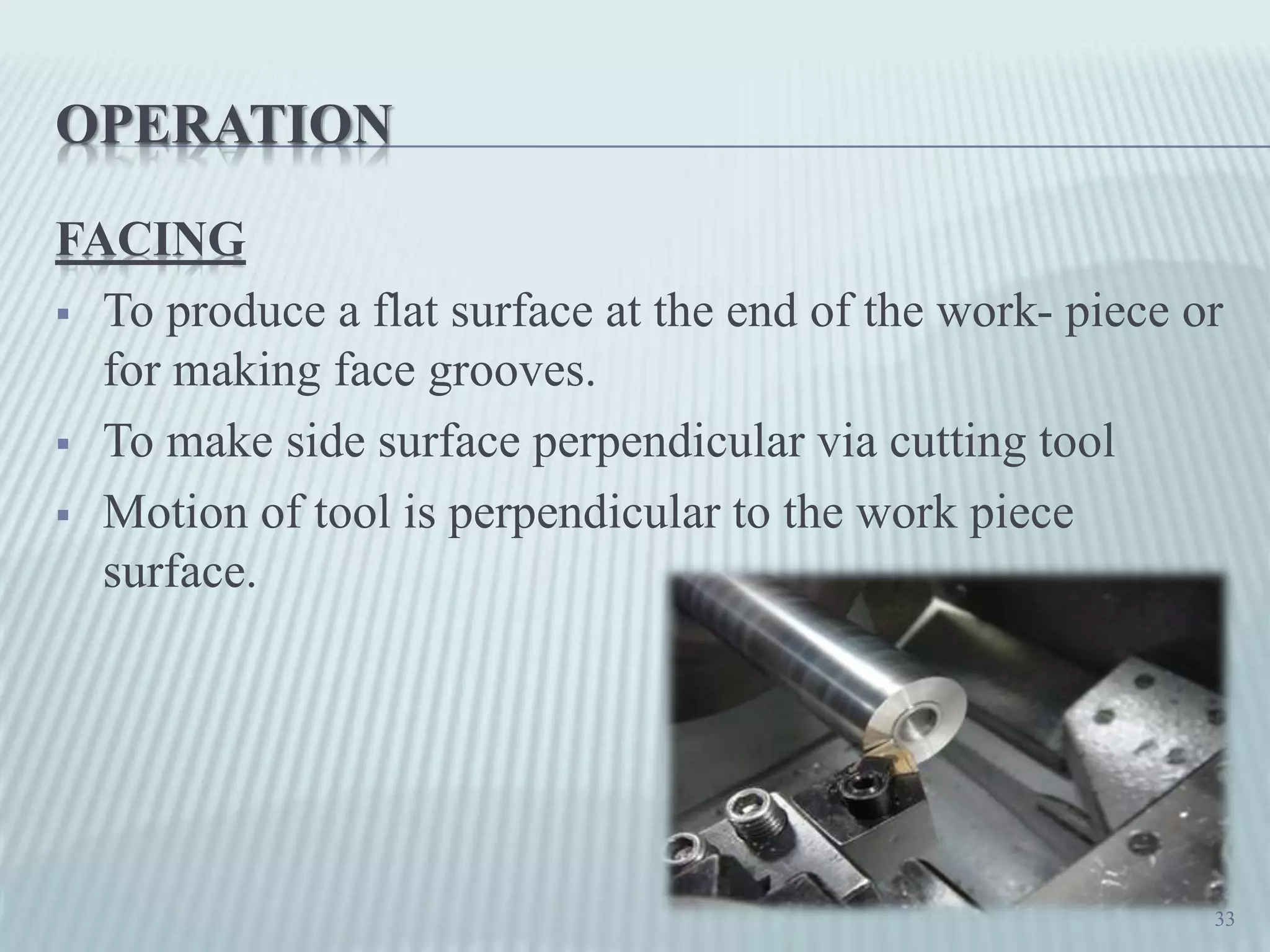
Process of producing flat surfaces on workpieces using facing cuts.
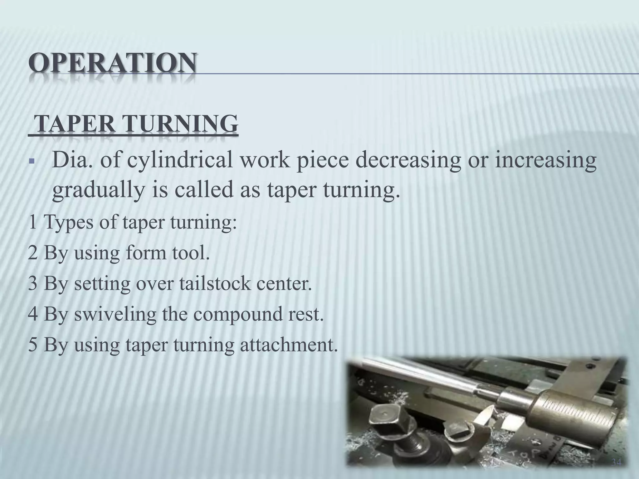
Different methods used for taper turning on cylindrical workpieces.
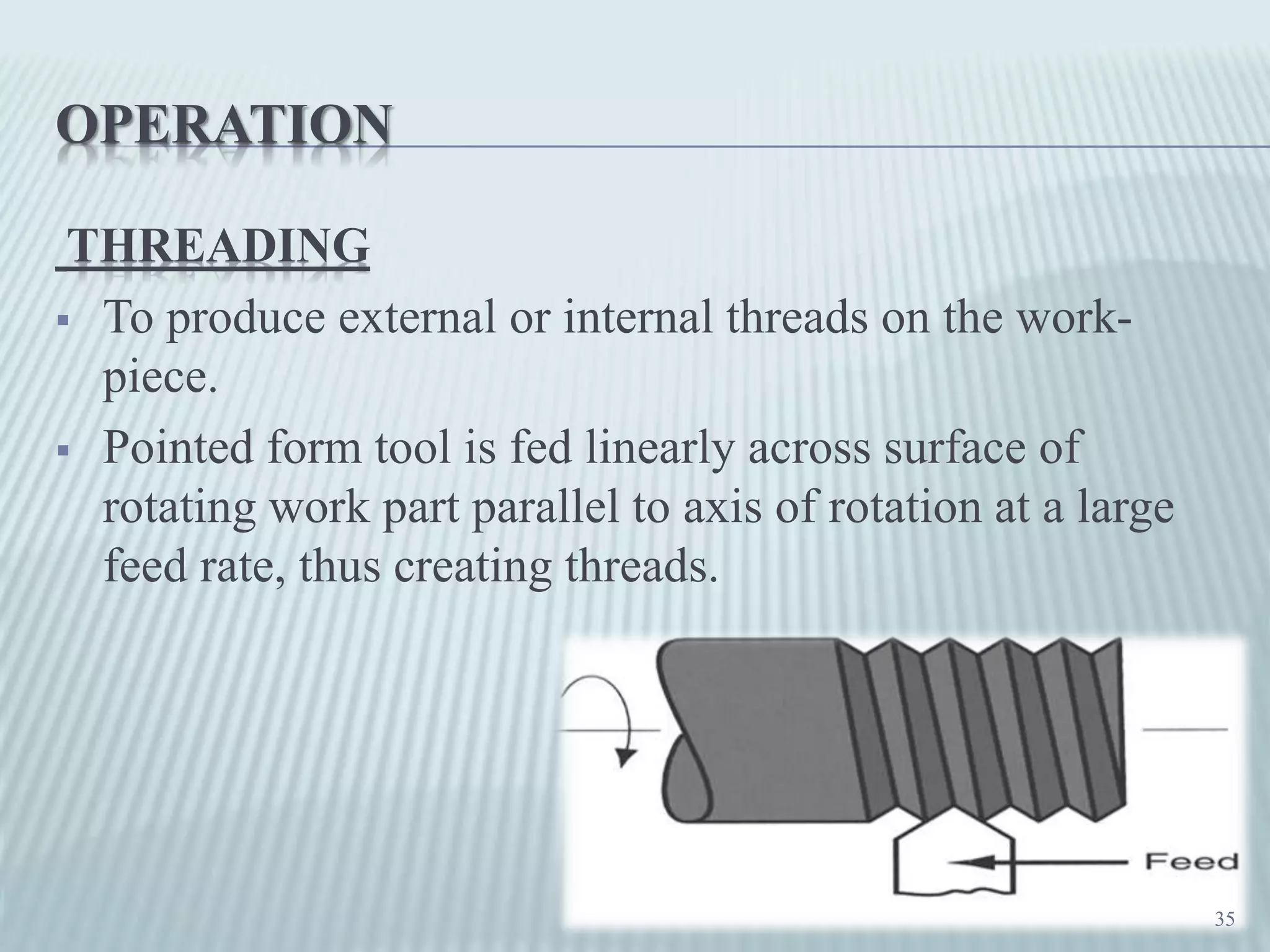
How external and internal threads are created on workpieces through threading.
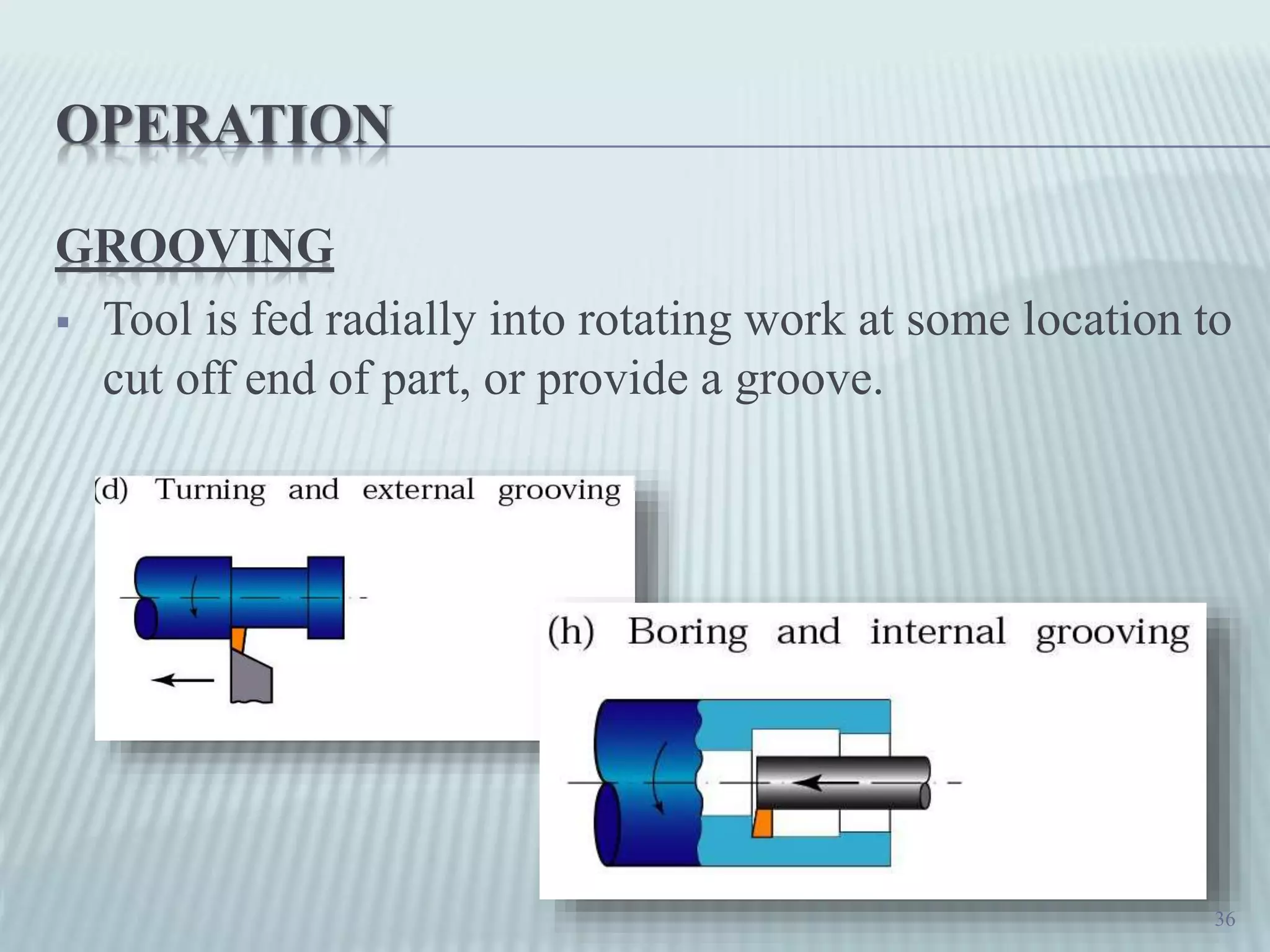
Explanation of grooving, focused on cutting grooves or part-offs.
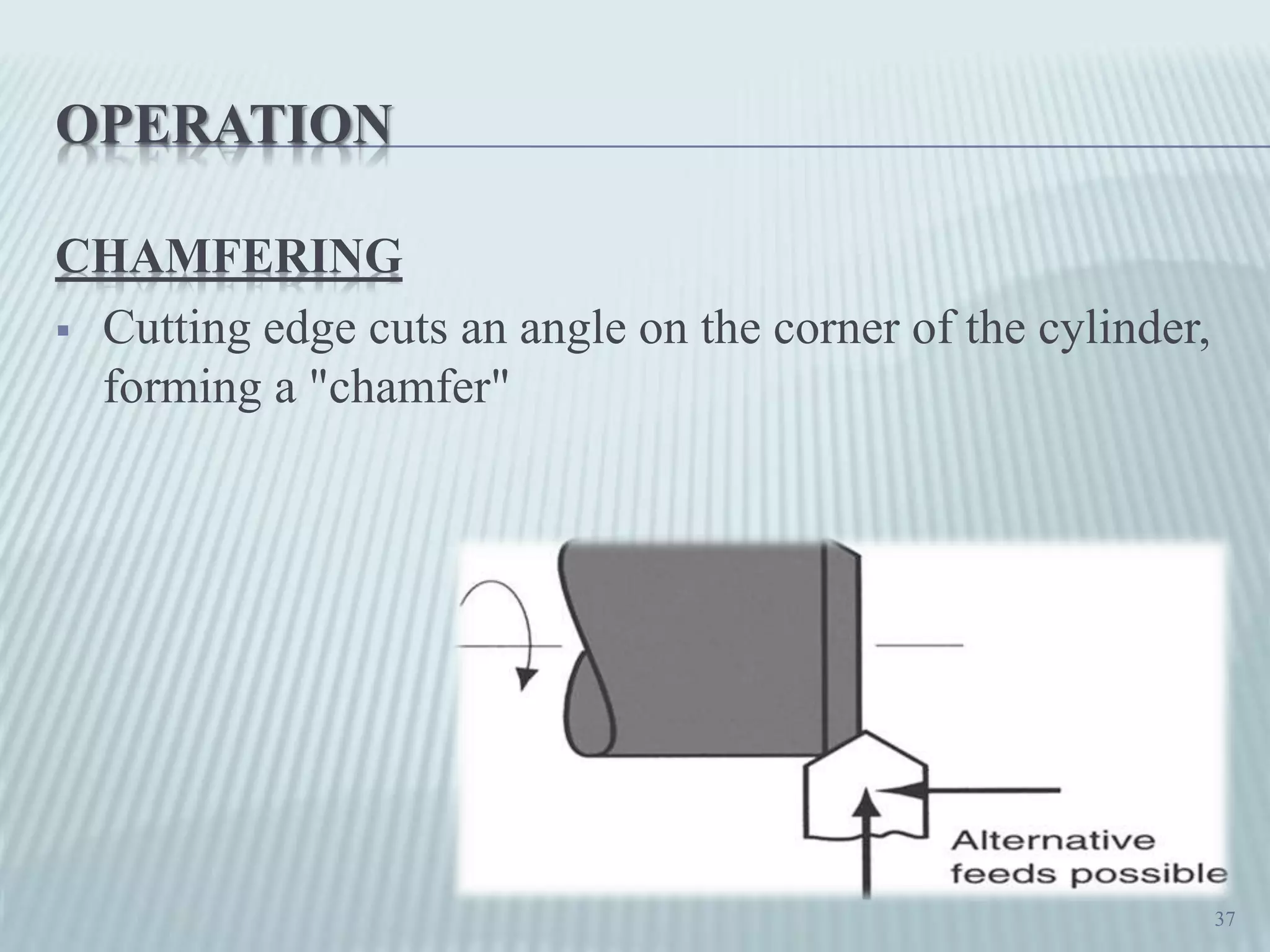
Process of creating angled edges on cylindrical workpieces through chamfering.
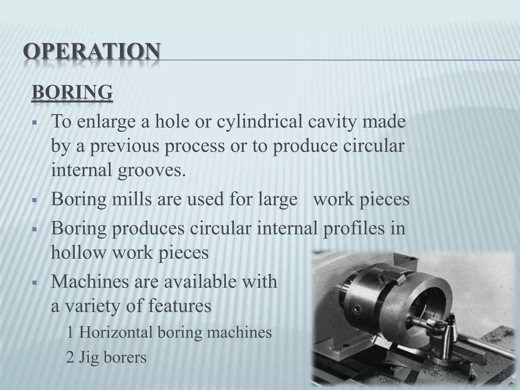
Boring techniques for enlarging existing holes in workpieces.
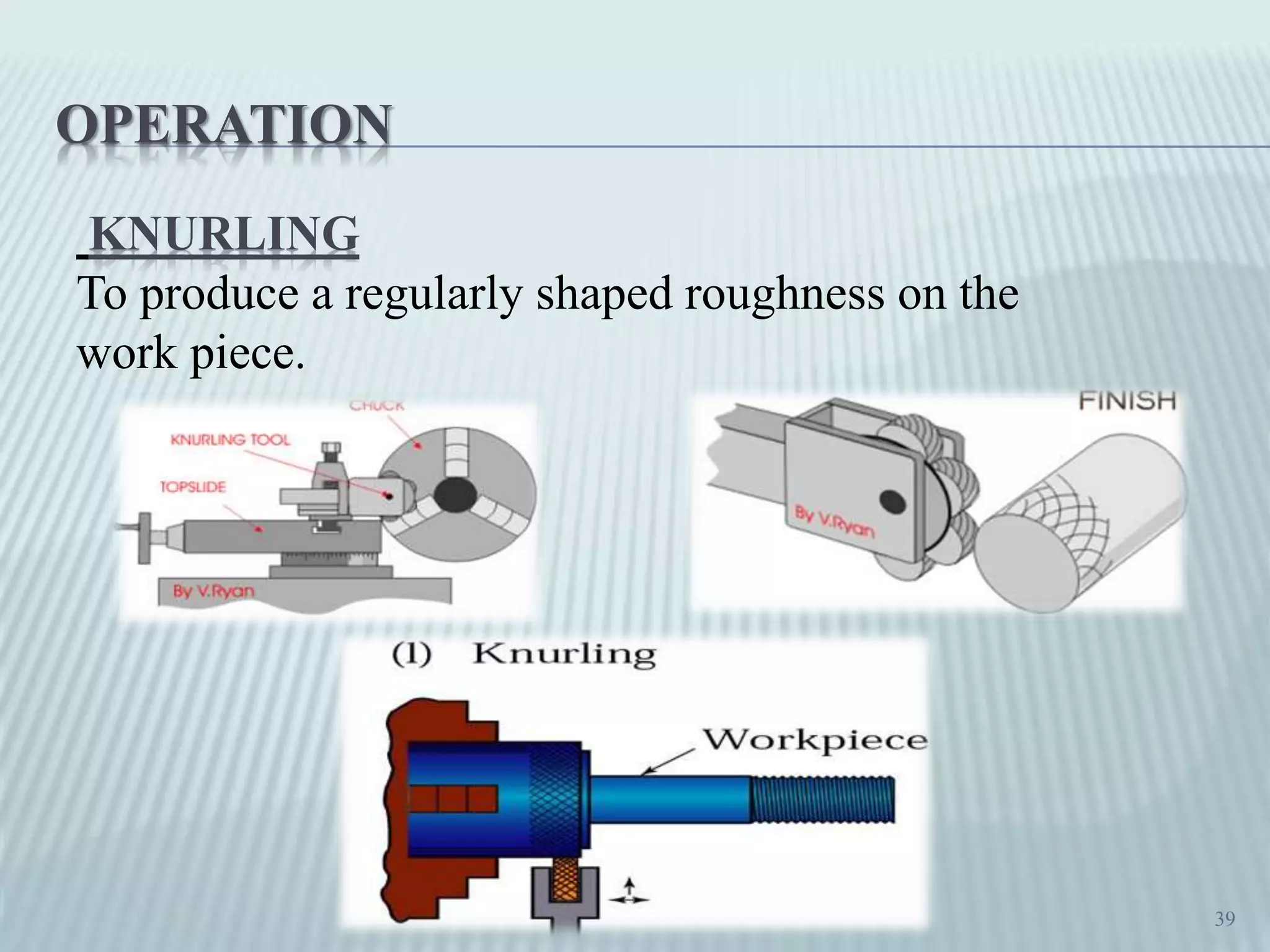
Description of knurling, used to produce patterns on workpieces for grip.
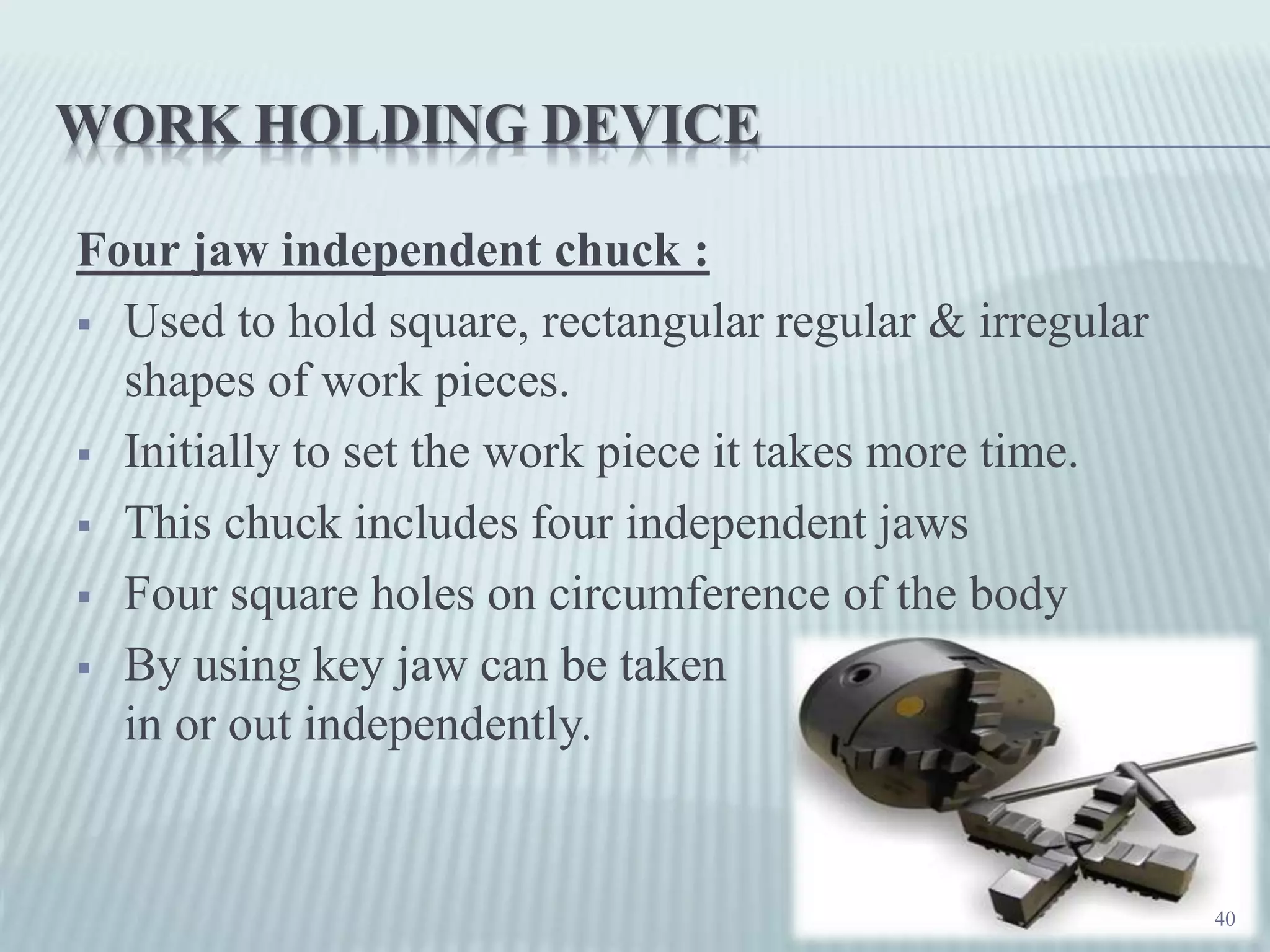
Features and applications of the four-jaw independent chuck for various shapes.
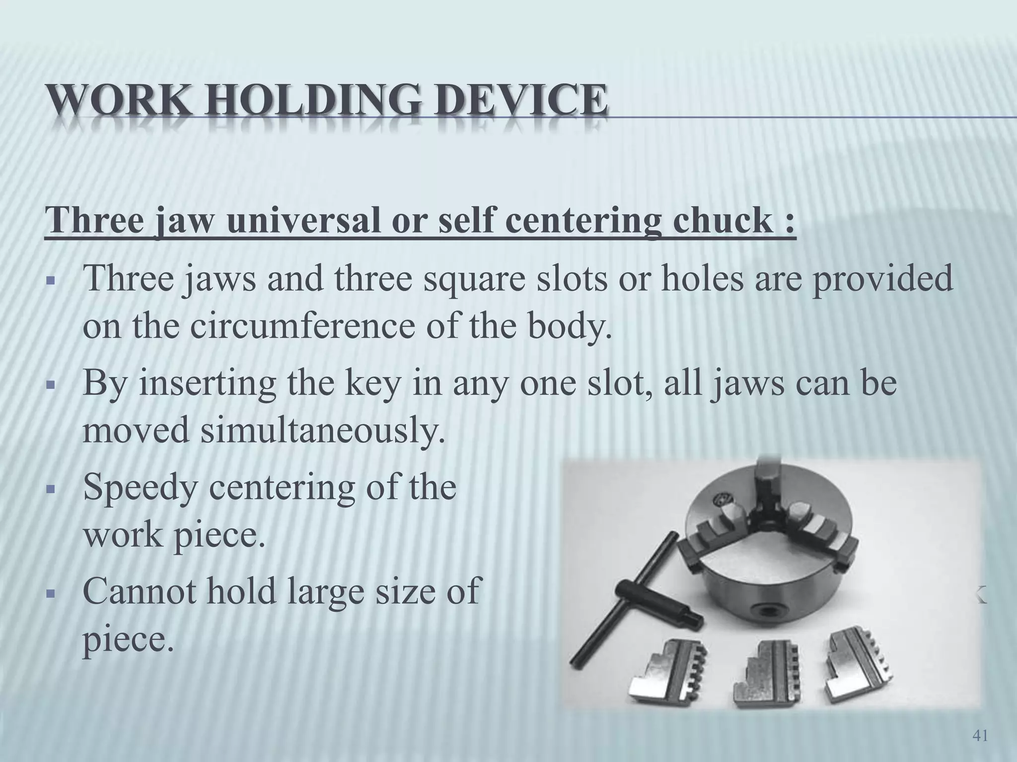
Overview of three-jaw universal chucks for faster centering of workpieces.
Functionality of combination chucks that allow simultaneous or independent jaw adjustments.
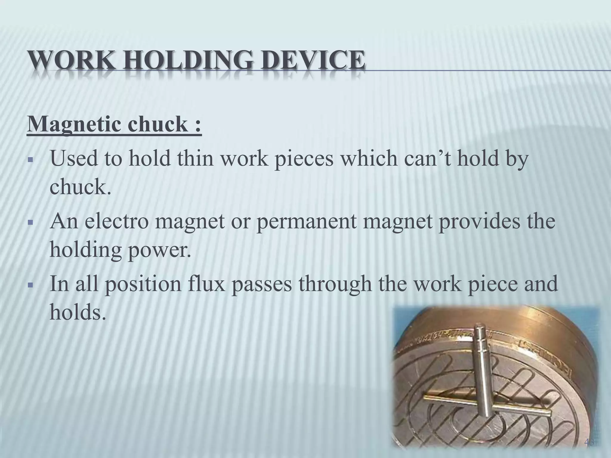
Uses of magnetic chucks for thin workpieces that cannot be held by regular chucks.
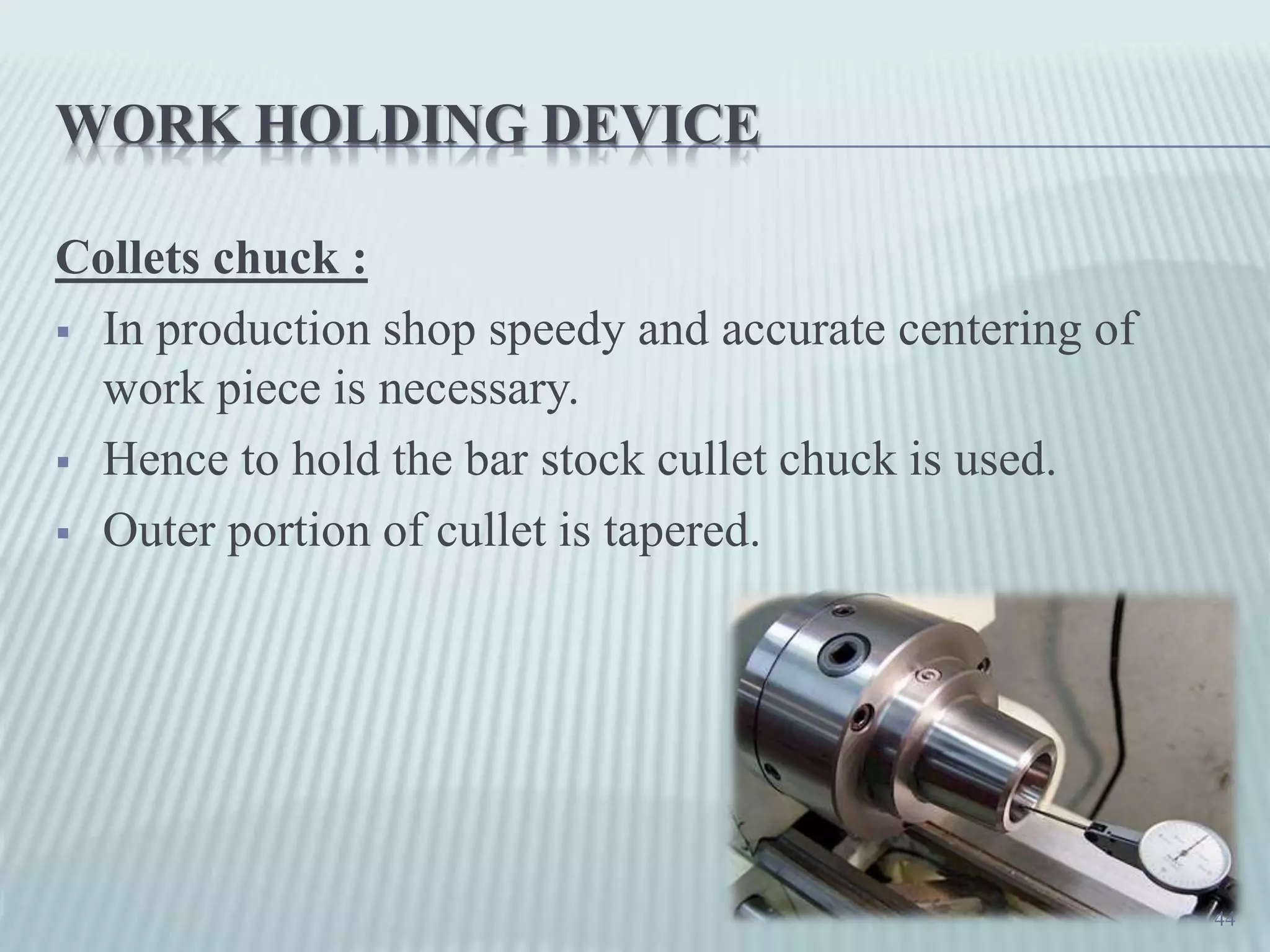
Design of collet chucks ensuring rapid and precise workpiece centering.
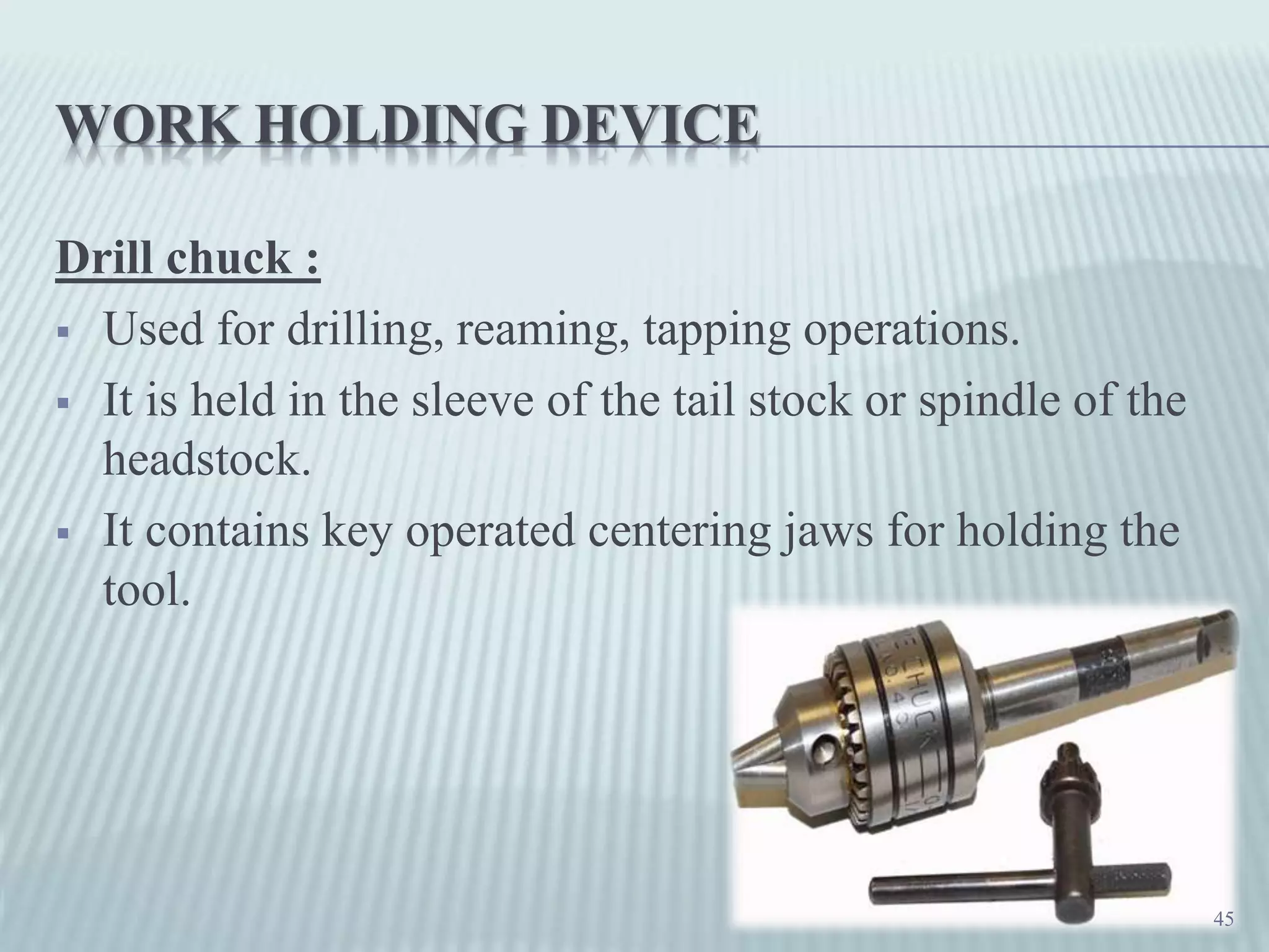
Details on drill chucks used for drilling and reaming operations.
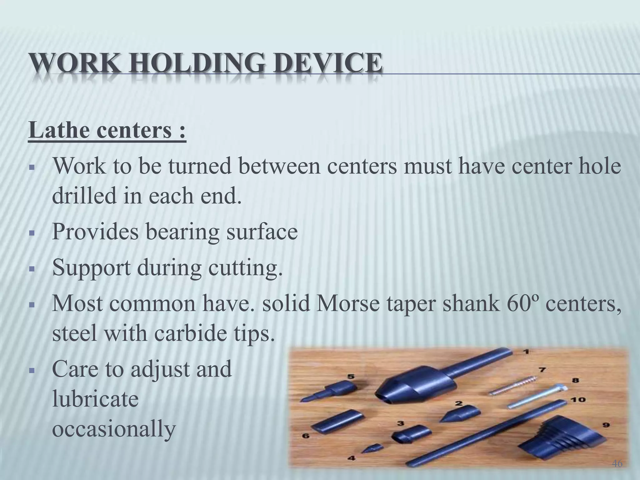
Importance of lathe centers in providing support during turning operations.
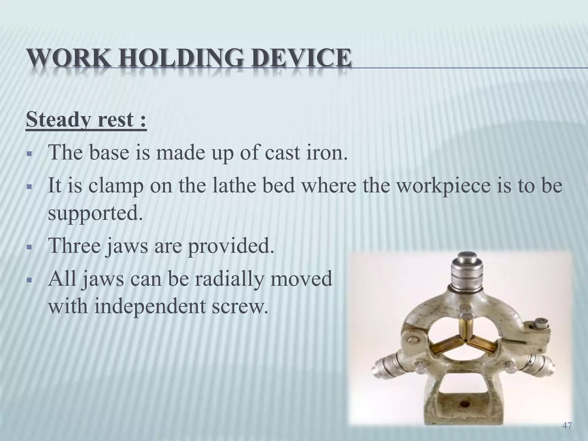
Role of the steady rest in supporting workpieces during machining.
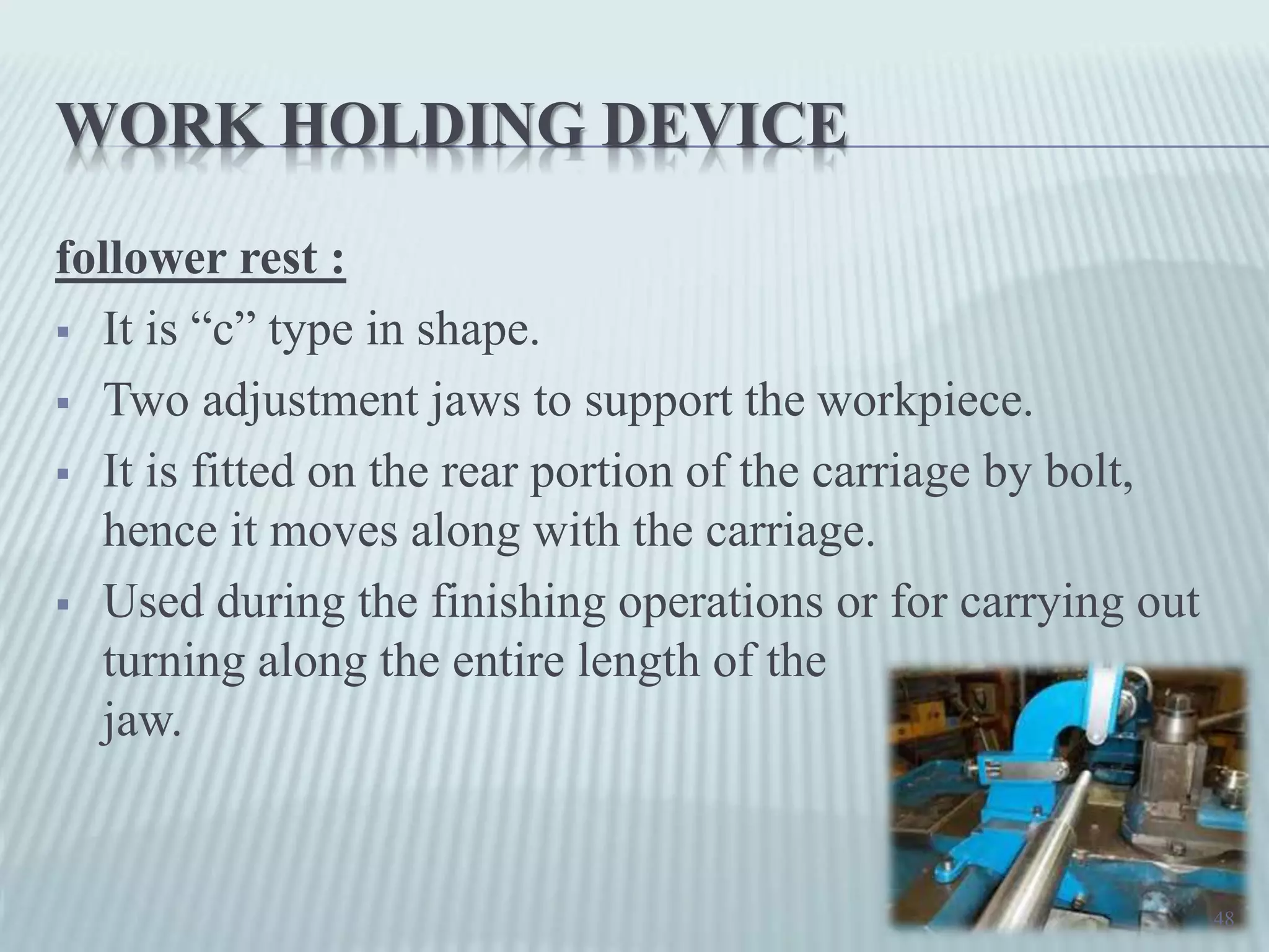
Functionality and positioning of the follower rest during lathe operations.
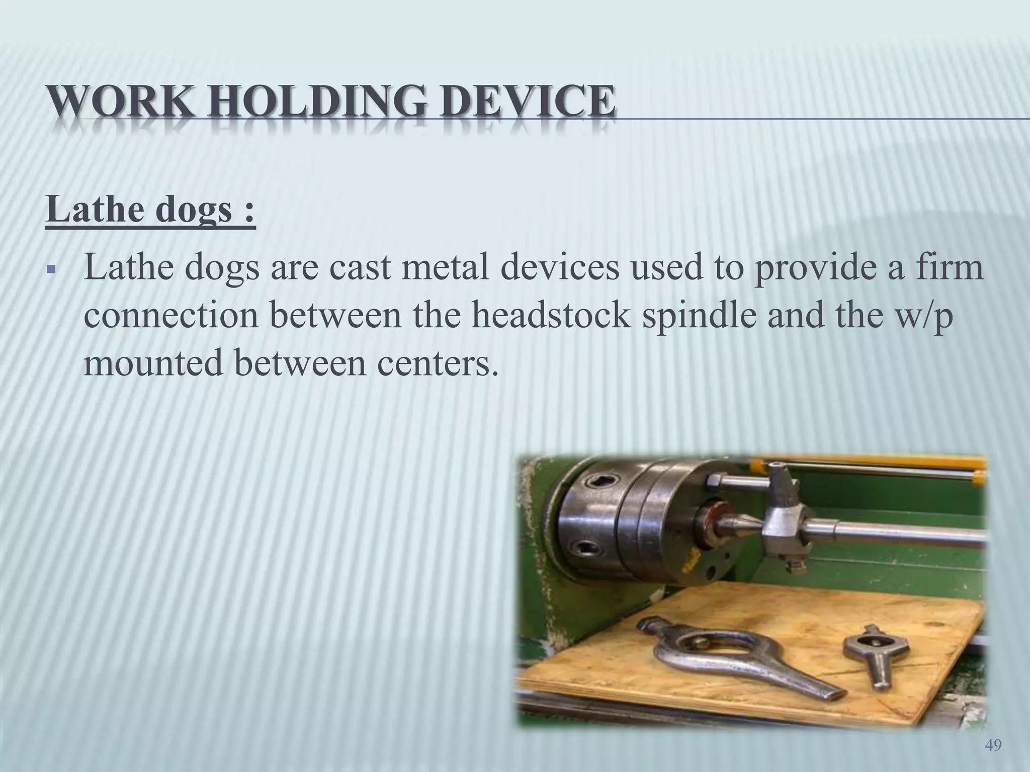
Description of lathe dogs used for connecting workpieces to spindle.
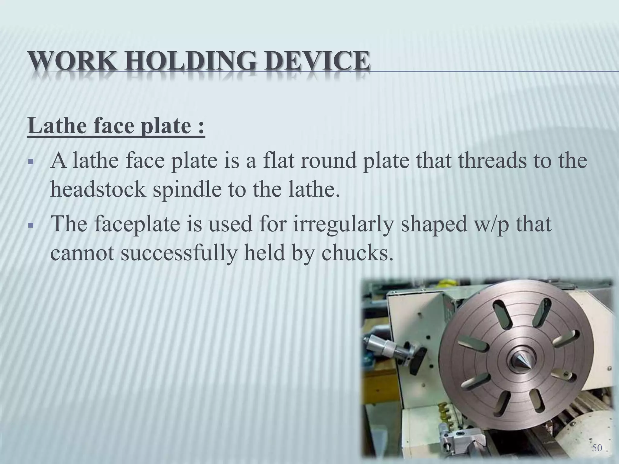
Benefits of using faceplates for holding irregularly shaped workpieces.
Closing gratitude expressed to the audience for their attention.


