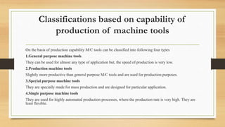
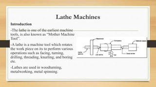
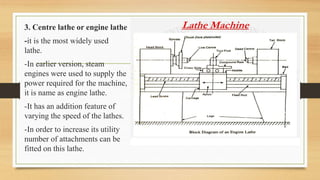
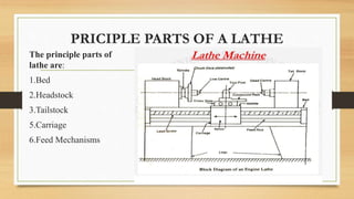
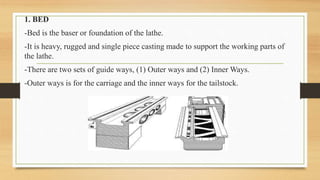
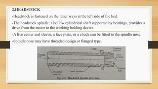
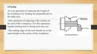
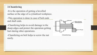
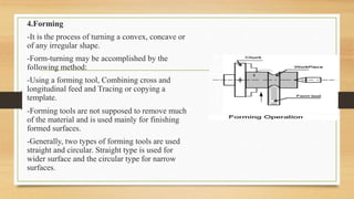
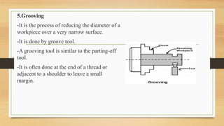
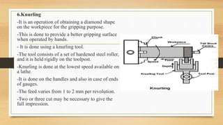
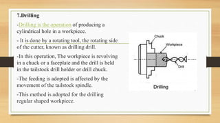
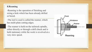
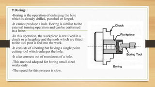
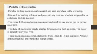
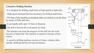
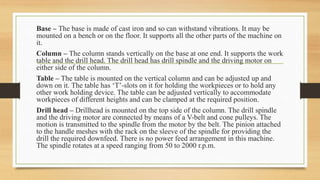
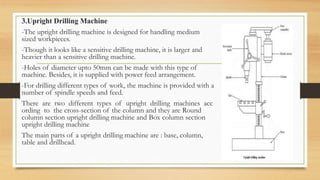
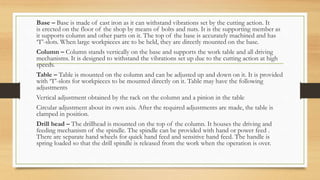
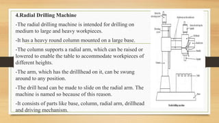
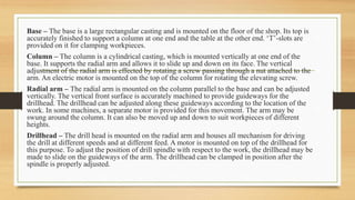
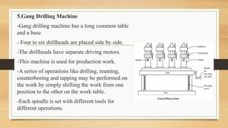
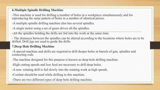
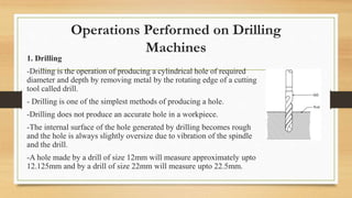
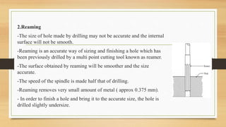
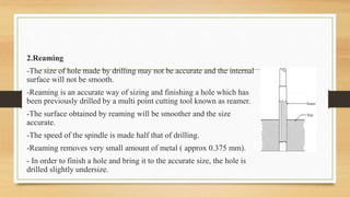
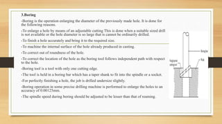
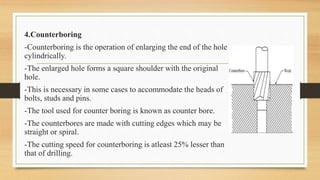
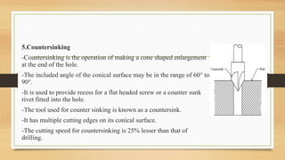
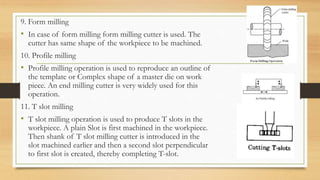
The document discusses different types of machine tools and lathe machines. It provides classifications of machine tools based on production capability, and describes the main parts and operations of lathe machines. It also covers different types of drilling machines such as portable, sensitive, upright, radial, gang and multiple spindle drilling machines.
The document discusses lathe machines. It defines a lathe as a machine that removes metal from a workpiece to shape it. It then describes some key parts of a lathe like the bed, headstock, tailstock, and carriage. It explains the working principle of a lathe where the cutting tool is fed into a rotating workpiece to shape it. Finally, it summarizes some common lathe operations like turning, facing, drilling and threading.
This presentation briefly tells about the classification of Gears. It includes information about spur, helical, bevel, herringbone, rack and pinion, internal and external gears.
Introduction
The shaper machine is a machine that can make slots and grooves using a thin cutting tool. The linear cutting motion is provided by the “Whitworth Quick-Return Mechanism“. While the feed motion is supplied by the mechanism illustrated in this report "The shaper feed Mechanism”. During shaping, cutting and infeed motions are carried out by the tool, while the feed motion is performed by the table carrying the work piece.
The Shaper Feed Mechanism
- By using a combination of various shaped links we can change the rotating motion supplied by the motor to a linear cyclic motion.
- In order to obtain a precise groove width and a calculated cyclic longitudinal pitch the use of this mechanism was important.
Operation: (From figure 1)
• Gear (1) obtaining its motion from the quick feed mechanism’s input rotates.
• The gear moves the link (2).
• Body (3) and the ratchet wheel (4) are mounted on the same shaft. Motion is transmitted from link 2 to body (3).
• Body (3) contains a pawl which reciprocates about its axis moving the ratchet wheel with it.
• The gear rotates a screw which is mounted on its shaft.
• The nut mounted on the screw moves linearly providing the motion of the table resulting in the feed motion.
Definition, Use, Types of beariings, Types of Journal bearing, Materials for journal bearing, Failures of journal bearing, Design terms for journal bearing, Types of roller contact bearing, applications of roller contact bearing, Designation of roller contact bearing, Design terms for roller contact bearing, comparison between journal and roller bearings, characteristics of bearings, selection procedure of bearings
This document discusses various types of boring machines and their uses. It describes horizontal and vertical boring machines, floor type boring machines, turret type boring machines, and precision jig boring machines. It also discusses boring bars and tool holders, including adjustable, damped, and line boring bars as well as boring and facing heads. Jig boring machines resemble vertical milling machines and are designed for accuracy through rigidity and precise measurement capabilities.
The document discusses different types of modified lathes, including capstan, turret, and automatic lathes. Capstan and turret lathes improve on center lathes by including an indexable turret holding multiple tools to allow for faster job set-up and overlapping of operations. Automatic lathes further automate the process by automatically controlling tool movement and sequencing. Single spindle automatics operate on one component at a time using either Swiss or turret screw machine designs, while multi-spindle automatics improve productivity further by processing multiple components simultaneously in parallel or progressively.
This document provides an overview of different types of gears including their key components and terminology. It discusses common gear types like spur gears, helical gears, bevel gears, and worm gears. For each type it provides examples of advantages and disadvantages as well as typical applications. The document also discusses gear materials and common modes of gear failure such as scoring, wear, pitting, plastic flow, and tooth fracture.
Design of Flat belt, V belt and chain drivesDr. L K Bhagi
Geometrical relationships, Analysis of belt tensions, Condition for maximum power transmission, Characteristics of belt drives, Selection of flat belt, V- belt, Selection of V belt, Roller chains, Geometrical relationship, Polygonal effect, Power rating of roller chains, Design of chain drive, Introduction to belt drives and belt construction, Introduction to chain drives
The document discusses different types of gears including spur gears, helical gears, herringbone gears, rack and pinion gears, bevel gears, and worm gears. It provides details on each type, such as how they transmit power at different angles, speeds, and ratios. Spur gears have parallel teeth and are used in devices like electric screwdrivers. Helical gears operate more smoothly than spur gears. Herringbone gears are a type of double helical gear. Rack and pinion gears convert rotational motion to linear motion. Bevel gears transmit power at intersecting shafts. Worm gears provide large gear reductions and can easily turn in one direction.
This document provides an overview of lathe machine training, including:
1) It describes the basic principle of a lathe machine as removing metal from a workpiece to achieve a desired shape and size.
2) It outlines the main components of a lathe such as the bed, headstock, carriage, tailstock, and feed rod.
3) It discusses different types of lathes including engine lathes, turret lathes, automatic lathes, and CNC lathes.
4) It details common lathe operations like turning, boring, drilling, and threading. Accessories like chucks and centers are also covered.
This document provides information about mechanical engineering and the centre lathe. It discusses the main parts and functions of the lathe, including the headstock, bed, carriage, cross-slide, apron, tailstock, tool post, and quick-change gearbox. It also covers lathe safety, types of lathes, cutting speeds, lathe accessories such as centers, chucks, faceplates, and work holding methods. The objectives are to identify lathe parts and their purposes, discuss safety procedures, calculate cutting speeds, and describe various lathe accessories.
This document discusses various gear manufacturing methods including forming processes like extrusion, stamping, and powder metallurgy as well as machining processes like gear shaping, hobbing, and other gear cutting methods. Extrusion can produce gears of any tooth shape in high volumes but is generally used for smaller non-ferrous gears. Stamping is best for low cost, low precision production while powder metallurgy allows for customizable material properties and reduces machining. Gear shaping and hobbing are true generating processes that cut gear teeth through the motion of cutting tools. Hobbing produces the most accurate gears due to averaging of errors across multiple teeth cuts.
This document discusses lathe operations and provides details on various operations like facing, turning, knurling, parting off, drilling, boring, thread cutting, and taper turning. It explains the basic principles and methods for each operation. The objective of the course is to help students understand different types of lathes, lathe operations, work holders, tool holders, lathe attachments, and automatic lathes. The outcome is for students to be able to use lathe machines and understand the importance of lathe tools and lathes. [/SUMMARY]
Fasteners and Fasteners types
Bolts and nuts
fasteners identification
Sizes and descriptions of bolts and nuts
official website: http://bu.edu.eg/staff/alielgazar3
This document provides information about various machining processes and machine tools. It describes machining as a metal removing process using machine tools and cutting tools. Lathe machines are commonly used to produce cylindrical surfaces and other operations like turning, drilling, boring, etc. Other machine tools discussed include milling machines, drilling machines, grinding machines, shaping machines, and planning machines. The document provides detailed descriptions of various operations that can be performed on these machines.
Couplings are used to connect two shafts together for power transmission. The main types are rigid couplings for aligned shafts, like flanged, split, keyed, and friction couplings, and flexible couplings for misaligned shafts, like universal joints, constant velocity joints, and fluid couplings. Flexible couplings allow for minor axial, angular, and parallel misalignment between shafts. Common flexible couplings include jaw & spider couplings, tyre couplings, and bellows couplings. Couplings allow power transmission between shafts, accommodate shaft misalignment, reduce shocks, and make assembly/disassembly easier.
This document provides definitions and principles related to locating and clamping in jigs and fixtures design. It defines a jig as a device that holds work and locates the tool path, and a fixture as a device that locates work on a machine table. It discusses locating principles like six point location and 3-2-1 principle. It also covers various locating and clamping devices like pins, buttons, V-locators, and different types of clamps. The document aims to provide fundamental guidelines for effective design of jigs and fixtures.
Bevel gears are gears that have a 45 degree angle on their edge which allows them to change the direction of rotation by 90 degrees. There are different types of bevel gears including straight bevel gears which have conical pitch surfaces and tapering teeth, spiral bevel gears which have curved teeth allowing gradual contact, and zerol bevel gears which are similar to straight bevel gears but with curved teeth where the ends align with the axis. Hypoid bevel gears are similar to spiral bevel gears but have hyperbolic pitch surfaces instead of conical, allowing for larger pinion diameters and longer life. Bevel gears can transfer motion through 90 degrees and usable gear ratios depend on the number of teeth.
Like Comment and download
Belt is a Flexible Mechanical element that transmit power from one shaft to another
Gear Train
Ex: Automobile, engines etc.
Chain Drive
Ex : Bi-cycle , Motor cycle etc.
Belt Drive
Ex: Rice mills, sewing machine etc.
Rope Drive
Ex: lift, crane etc
Broaching is a machining process where a broach tool with multiple cutting teeth is pushed or pulled through a workpiece to cut it into the desired shape. Broaching provides good dimensional accuracy and surface finish. There are different types of broaching machines like horizontal, vertical pull, continuous, and rotary table machines. Broaching is used to manufacture precision components like bearing caps, gears, and splines. It provides interchangeability but the initial costs of broaches and machines are high.
This document provides information about milling machines and milling operations. It describes the major parts and differences between horizontal and vertical milling machines. Various milling operations like face milling, end milling and slot milling are explained along with principles of up and down milling. Different types of milling cutters are classified and their applications discussed. Specifications of milling machines like worktable size, movements in X, Y and Z directions and motor power are also covered.
The document discusses various types of power transmission devices used to transfer motion and power between rotating shafts, including belt drives, chain drives, and gear drives. Belt drives can be flat, V-belt, timing or circular belts and are used to connect shafts over long distances. Chain drives use sprocket wheels connected by roller or silent chains. Gear drives include spur gears, helical gears, bevel gears, and worm gears to connect parallel, intersecting, or perpendicular shaft axes. Couplings like sleeve, split, flange, bush pin, and universal joints are also discussed for connecting shafts while allowing some misalignment or movement.
Metal cutting involves removing unwanted material from a workpiece. In orthogonal cutting, the cutting tool edge is perpendicular to the direction of motion, so chip flow is perpendicular to the cutting edge. In oblique cutting, the cutting tool edge is at an angle to the direction of motion, so chip flow is sideways. Orthogonal cutting results in higher heat concentration, shorter tool life, and poorer surface finish than oblique cutting. Oblique cutting is used for most industrial processes like drilling and milling.
Gears are components that transmit rotational motion between two shafts. There are several types of gears classified by the position of their shafts, including spur gears where the teeth are parallel to the axis of rotation, helical gears which are cut at an angle, and bevel gears where the shafts meet at an angle. Gears are used in many machines and mechanisms to increase torque or change the speed and direction of rotation between two shafts.
The document discusses different types of lathe machines and their operations. It describes 7 types of lathes - speed lathe, engine lathe, bench lathe, tool room lathe, capstan and turret lathe, automatic lathe, and special purpose lathes. It also explains lathe operations like turning, facing, boring, drilling, threading and knurling. Additionally, it covers lathe accessories such as centers, chucks, faceplates, mandrels and rests that are used for holding and supporting workpieces.
This document provides information about lathe machines, including:
1. It describes the basic working principle of a lathe machine as securely holding a workpiece to turn and shape it against a single-point cutting tool.
2. It lists and briefly describes several common types of lathes - speed lathe, engine lathe, bench lathe, tool room lathe, capstan and turret lathe, and special purpose lathes.
3. It outlines the key construction parts of a lathe machine, including the bed, headstock, tailstock, carriage, feed mechanisms, and screw cutting mechanism.
A lathe is a machine that removes metal from a workpiece to shape it. It holds the workpiece firmly and rotates it at high speed while a cutting tool is fed into it. The main components of a lathe are the bed, headstock, tailstock, carriage, and feed mechanisms. There are several types of lathes classified based on their drive mechanism and purpose, including speed lathes, engine lathes, bench lathes, toolroom lathes, capstan and turret lathes, and automatic lathes. Lathes perform operations like turning, facing, drilling, boring, threading, and knurling using tools held in the tool post or turret. Workpieces are secured using chucks,
This document provides information about lathe machines, including their definition, main components, operations, specifications, safety precautions, and advantages of carbide and high-speed cutting tools. A lathe machine is used to shape and size metal workpieces through operations like turning, grooving, and drilling. It discusses the types of lathe machines and describes the headstock, tailstock, carriage, cross slide, and tool post as main components. Facing, turning, grooving, and other operations are outlined. Jigs and fixtures are used to increase accuracy and automation.
i hope, it will helpful to the students and peoples in the search of topics mentioned
it is informative to study to even get passing marks or for revision
Oliver piercey 3666 assignsubmission_file_milling machine presentationAnoushkaOttley
A milling machine is used to machine sheet and some tubular materials. It has three axes - X, Y, and Z - to feed the workpiece and can perform operations like chamfering, face milling, and slot milling. Key components include the table, saddle, knee, ram, and spindle/tool head. Safety precautions when using a milling machine include guards, correct PPE like safety glasses and steel-toe boots, and checking speeds and axes positions. A lathe is used to machine cylindrical materials and cut threads. It has two axes and a bed, carriage, compound rest, and headstock/tailstock. Operations include turning and screw cutting. Slurry is used to cool
The document provides information about lathes, including:
1. A lathe is a basic machine tool used to shape materials by rotating the workpiece against various cutting tools. It can perform operations like turning, facing, knurling, and thread cutting.
2. The main components of a lathe are the bed, headstock, carriage, and tailstock. The headstock holds the workpiece, the carriage holds the cutting tool, and the tailstock supports the other end of the workpiece.
3. Common lathe operations include turning, facing, parting off, knurling, thread cutting, grooving, drilling, boring, and reaming. Tapers can be cut using tools,
The document describes the main parts and working principle of a lathe machine. A lathe machine holds and rotates the workpiece to perform operations like turning, facing, threading, and drilling using a cutting tool. It consists of a bed, headstock, carriage, tailstock, chuck, and tool post. The rotating workpiece is cut by moving the tool against it manually or automatically using the carriage. Common operations include turning, facing, grooving and cutting external and internal threads.
The document discusses lathe machines and their operation. It defines a lathe as a machine that removes metal from a workpiece to shape it. The main parts of a lathe are identified as the bed, headstock, tailstock, and carriage. Lathes operate by rotating the workpiece and moving a fixed cutting tool into it. Common lathe operations include turning, facing, drilling, grooving and parting.
The document provides instructions for maintaining the output shaft gear box of a steel transfer car. It details dismantling the damaged output shaft assembly, which involves removing the gear coupling using a hydraulic press. Reassembly is also described, such as fixing split plates and adjusting them before recoupling the gear. The procedure aims to repair the output shaft assembly efficiently and with quality.
This document provides information about machine tools and lathes. It discusses that machine tools are power operated machines that cut metal using cutting tools. It then describes the major components of lathes, including the headstock, spindle, tailstock, carriage, apron, and bed. It explains the different motions in machining like primary and auxiliary motion. The document also summarizes various classifications of machine tools and discusses performance criteria. Finally, it covers topics like specification, drive systems, speed changing methods, and work holding devices in lathes.
internship report on working & types of drilling machineprabhatkumarsamal
The document discusses different types of drilling machines and their uses. It describes portable drilling machines, bench drilling machines, upright drilling machines, and radial drilling machines. It provides details on the working principles, parts, specifications, operations, and applications of drilling machines. Drilling machines are used to drill holes in workpieces and can perform operations like drilling, boring, reaming, counterboring, countersinking, spot facing and tapping.
The lathe machine was invented in 1740 and is used to rotate workpieces so that cutting tools can shape the workpiece. It consists of a bed with ways to guide the carriage that holds the cutting tool. Other main components include the headstock, spindle, chuck, tailstock, and lead screw. The lathe is used to perform operations like turning, facing, drilling, boring, and threading through positioning the cutting tool relative to the rotating workpiece. Safety precautions when using the lathe include wearing protective equipment and keeping the work area clear of hazards.
1. The document discusses different types of turning machines, including center lathes, turret lathes, capstan lathes, and automatic lathes. It describes the basic parts and functions of a center lathe like the bed, headstock, tailstock, and carriage.
2. Various lathe operations are outlined such as plain turning, taper turning, drilling, boring, and knurling. Special attachments for milling and grinding are also mentioned.
3. Automatic lathes are classified as either magazine-loaded or chucking-type depending on how the workpiece is loaded and removed for machining duplicate parts automatically.
Lathe is one of the most important machine tools in the metal working industry. A lathe operates on the principle of a rotating work-piece and a fixed cutting tool.
Lathe machine also called “Engine Lathe” because the first type of lathe was driven by a steam engine
The document discusses drilling operations and drilling machines. It provides details on the construction of drilling machines including their base, column, drill head, table, and spindle drive and feed mechanisms. It also describes various tool and work holding devices used in drilling like drills, chucks, v-blocks, and drilling jigs. Finally, it outlines different types of drilling operations such as drilling, boring, counterboring, tapping, and reaming.
A lathe is a machine tool that is used to remove material from a rotating workpiece to produce cylindrical objects. It works by holding the workpiece firmly and rotating it at high speeds while a cutting tool is fed into the workpiece removing material to create the desired shape or features. Major components of a lathe include the bed, headstock, tailstock, carriage assembly, and main drive. Common lathe operations are turning, facing, knurling, taper turning, thread cutting, and drilling.
This document provides information about various machine shop machines and their functions. It introduces lathes, milling machines, shaper machines, planer machines, and drilling machines. It describes that a lathe rotates a workpiece to cut, shape, and form symmetrical objects. A milling machine uses rotating cutters to remove material. A shaper machine uses a reciprocating ram and single-point cutting tool. A planer machine has a moving workpiece and stationary cutting tool. Drilling machines cut holes using a drilling tool attached to a spindle.
Henry Maudslay is considered the father of machine tool technology for his inventions around 1800, including a metal lathe that enabled mass production with interchangeable parts. A lathe is used to machine cylindrical workpieces and consists of main parts like the bed, headstock, tailstock, carriage, and tool post. Different lathe types include engine lathes, turret lathes, and automatic lathes. The document discusses lathe parts and mechanisms in detail.
Similar to Machine tools basic mechanical engineering sem-II (20)
Digital Twins Computer Networking Paper Presentation.pptxaryanpankaj78
A Digital Twin in computer networking is a virtual representation of a physical network, used to simulate, analyze, and optimize network performance and reliability. It leverages real-time data to enhance network management, predict issues, and improve decision-making processes.
Applications of artificial Intelligence in Mechanical Engineering.pdfAtif Razi
Historically, mechanical engineering has relied heavily on human expertise and empirical methods to solve complex problems. With the introduction of computer-aided design (CAD) and finite element analysis (FEA), the field took its first steps towards digitization. These tools allowed engineers to simulate and analyze mechanical systems with greater accuracy and efficiency. However, the sheer volume of data generated by modern engineering systems and the increasing complexity of these systems have necessitated more advanced analytical tools, paving the way for AI.
AI offers the capability to process vast amounts of data, identify patterns, and make predictions with a level of speed and accuracy unattainable by traditional methods. This has profound implications for mechanical engineering, enabling more efficient design processes, predictive maintenance strategies, and optimized manufacturing operations. AI-driven tools can learn from historical data, adapt to new information, and continuously improve their performance, making them invaluable in tackling the multifaceted challenges of modern mechanical engineering.
Supermarket Management System Project Report.pdfKamal Acharya
Supermarket management is a stand-alone J2EE using Eclipse Juno program.
This project contains all the necessary required information about maintaining
the supermarket billing system.
The core idea of this project to minimize the paper work and centralize the
data. Here all the communication is taken in secure manner. That is, in this
application the information will be stored in client itself. For further security the
data base is stored in the back-end oracle and so no intruders can access it.
Blood finder application project report (1).pdfKamal Acharya
Blood Finder is an emergency time app where a user can search for the blood banks as
well as the registered blood donors around Mumbai. This application also provide an
opportunity for the user of this application to become a registered donor for this user have
to enroll for the donor request from the application itself. If the admin wish to make user
a registered donor, with some of the formalities with the organization it can be done.
Specialization of this application is that the user will not have to register on sign-in for
searching the blood banks and blood donors it can be just done by installing the
application to the mobile.
The purpose of making this application is to save the user’s time for searching blood of
needed blood group during the time of the emergency.
This is an android application developed in Java and XML with the connectivity of
SQLite database. This application will provide most of basic functionality required for an
emergency time application. All the details of Blood banks and Blood donors are stored
in the database i.e. SQLite.
This application allowed the user to get all the information regarding blood banks and
blood donors such as Name, Number, Address, Blood Group, rather than searching it on
the different websites and wasting the precious time. This application is effective and
user friendly.
Determination of Equivalent Circuit parameters and performance characteristic...pvpriya2
Includes the testing of induction motor to draw the circle diagram of induction motor with step wise procedure and calculation for the same. Also explains the working and application of Induction generator
This study Examines the Effectiveness of Talent Procurement through the Imple...DharmaBanothu
In the world with high technology and fast
forward mindset recruiters are walking/showing interest
towards E-Recruitment. Present most of the HRs of
many companies are choosing E-Recruitment as the best
choice for recruitment. E-Recruitment is being done
through many online platforms like Linkedin, Naukri,
Instagram , Facebook etc. Now with high technology E-
Recruitment has gone through next level by using
Artificial Intelligence too.
Key Words : Talent Management, Talent Acquisition , E-
Recruitment , Artificial Intelligence Introduction
Effectiveness of Talent Acquisition through E-
Recruitment in this topic we will discuss about 4important
and interlinked topics which are
Impartiality as per ISO /IEC 17025:2017 StandardMuhammadJazib15
This document provides basic guidelines for imparitallity requirement of ISO 17025. It defines in detial how it is met and wiudhwdih jdhsjdhwudjwkdbjwkdddddddddddkkkkkkkkkkkkkkkkkkkkkkkwwwwwwwwwwwwwwwwwwwwwwwwwwwwwwwwwwwwwwwwwwwwwwwwwwwwwwwwwwwwwwwwwwwwwwwwwwwwwwwwwwwwwwwwwwwwwwwwwwwwwwwwwwwwwwwwwwwwwwwwwwwwwwwwwwwwwwwwwwwwwwwwwwwwwwwwwioiiiiiiiiiiiii uwwwwwwwwwwwwwwwwhe wiqqqqqqqqqqqqqqqqqqqqqqqqqqqqqqqqqqqqqqqqqqqqqqqqqqqqqqqqqqqqqqqqqqqqqqqqqqqqqqqqqqqqqqqqqqqqqqqqqqqqqqqqqqqqqqqqqqqqqqqqqqqqqqqqqqqqqqqqqqqqqqqqqqqqqqqqqqqqqqqqqqqqqqqqqqqqqqqqqqqqqqqqqqqqqqqqqqq gbbbbbbbbbbbbb owdjjjjjjjjjjjjjjjjjjjj widhi owqqqqqqqqqqqqqqqqqqqqqqqqqqqqqqqqqq uwdhhhhhhhhhhhhhhhhhhhhhhhhhhhhhhhhhhhhhhhhhhhhhhhhhhhhhhhhhhhhhhhhhhhhhhhhhhhhhhhhhhhhhhhhhhhhhhhhhhhhhhhhhhhhhhhhhhhhhhhhhhhhhhhhhhhhhhhhhhhhhhhhhhhhhhhhhhhhhhhhhhhhhhwqiiiiiiiiiiiiiiiiiiiiiiiiiiiiw0pooooojjjjjjjjjjjjjjjjjjjjjjjjjjjjjjjjjjjjjjjjjjjjjjjjjjjjjj whhhhhhhhhhh wheeeeeeee wihieiiiiii wihe
e qqqqqqqqqqeuwiiiiiiiiiiiiiiiiiiiiiiiiiiiiiiiiiiiiiiiiiiiiiiiiiiiiiiiiiiiiiiiiiiiiiiiiiiiiiiiiiiiiiiiiiiiiiiiiiiiiiiiiiiiiiiiiiiiiiiiiiiiiiiiiiiiiiiiiiiiiiiiiiiiiiiiiiiiiiiiiiiiiiiiiiiiiiiiiiiiiiiiiiiiiiiiiiiiiiiiiiiiiiiiiiiiiiiiiiiiiiiiiiiiiiiiiiiiiiiiiiiiiiiiiiiiiiiiiiiiiiiiiiiiiiiiiiiiiiiiiiiiiiiiiiiiiiiiiiiiiiiiiiiiiiiiiiqw dddddddddd cccccccccccccccv s w c r
cdf cb bicbsad ishd d qwkbdwiur e wetwwwwwwwwwwwwwwwwwwwwwwwwwwwwwwwwwwwwwwwwwwwwwwwwwwwwwwwwwwwwwwwwwwwwww w
dddddddddddddddddddddddddddddddddddddddddddddddddddddddddddddddddddddddddddddddddddddddddddddddddddddddddddfffffffffffffffffffffffffffffffffffffffffffffffffffffffffffffffffffffffffffffffffffffffffffffffffffffffffffffffffffffffffffffffffffffffffffffffffffffffffffffffffffffffffffffffffffffffffffffffffffffffffffffffffffffw
uuuuhhhhhhhhhhhhhhhhhhhhhhhhe qiiiiiiiiiiiiiiiiiiiiiiiiiiiiiiiiiiiiiiiiiiiiiiiiiiiiiiiiiiiiiii iqqqqqqqqqqqqqqqqqqqqqqqqqqqqqqqqqqqqqqqqqqqqqqqqqqqqqqqqqqqqqqqqqqqqqqqqqqqqqqqqqqqqqqqqqqqqqqqqqqqqqqqqqqqqqqqqqqqqqqqqqqqqqqqqqqqqq eeeeeeeeeeeeeeeeeeeeeeeeeeeeeeeeeeeeeeeeeeeeeeeeeeeeeeeeeeeeeeeeeeeeeeeeeeeeeeeeeeeeeeeeeeeeeeeeee qqqqqqqqqqqqqqqqqqqqqqqqqqqqqqqqqqqqqqqqqqqqqqqqqqqqqqqqqqqqqqqqqqqqqqqqqqqqqqqqqqqqqqqqqqqqqqqqqqqqqqqqqqqqqqccccccccccccccccccccccccccccccccccccccccccccccccccccccccccccc ccccccccccccccccccccccccccccccccccc bbbbbbbbbbbbbbbbbbbbbbbbbbbbbbbbbbbbbbbbbbbbbbbbbbbbbbbbbbbbbbbbbbbbbbbbbbbbbbbbu uuuuuuuuuuuuuuuuuuuuuuuuuuuuuuuuuuuuuuuuuuuuuuuuuuuuuuuuuuuuuuuuuuuuuuuuuuuuuuuuuuuuuuuuuuuuuuuuuuuuuuuuuuuuuuuuuuuuuuuuuuuuuuuuuuuuuuuuuuuuuuuuuuuuuuuuuum
m
m mmmmmmmmmmmmmmmmmmmmmmmmmmmmmmmmmmmmmmmmmmmmmmmmmmmmmmmmmmmmmmmmmmmmmmmmmmmmmmmmmmmmmmmmmmmm m i
g i dijsd sjdnsjd ndjajsdnnsa adjdnawddddddddddddd uw
Open Channel Flow: fluid flow with a free surfaceIndrajeet sahu
Open Channel Flow: This topic focuses on fluid flow with a free surface, such as in rivers, canals, and drainage ditches. Key concepts include the classification of flow types (steady vs. unsteady, uniform vs. non-uniform), hydraulic radius, flow resistance, Manning's equation, critical flow conditions, and energy and momentum principles. It also covers flow measurement techniques, gradually varied flow analysis, and the design of open channels. Understanding these principles is vital for effective water resource management and engineering applications.
2. What are machine tools?
• Machine tools are defined as a tool which while holding the cutting tool
would be able to remove metal from the workpiece.
• Material is removed from the workpiece in order to generate desired
shape. Some examples of M/C tools are milling cutter, drill bit, shaper etc.
3. Classifications based on capability of
production of machine tools
On the basis of production capability M/C tools can be classified into following four types
1.General purpose machine tools
They can be used for almost any type of application but, the speed of production is very low.
2.Production machine tools
Slightly more productive than general purpose M/C tools and are used for production purposes.
3.Special purpose machine tools
They are specially made for mass production and are designed for particular application.
4.Single purpose machine tools
They are used for highly automated production processes, where the production rate is very high. They are
least flexible.
4. Lathe Machines
Introduction
-The lathe is one of the earliest machine
tools, is also known as “Mother Machine
Tool”.
-A lathe is a machine tool which rotates
the work piece on its to perform various
operations such as facing, turning,
drilling, threading, knurling, and boring
etc.
-Lathes are used in woodturning,
metalworking, metal spinning.
5. Classification of lathes
1. Bench lathe
-it is a small lathe which can be mounted on a bench or cabinet.
-It is used for small and Precision work as it is very accurate.
-This usually provided with the attachment as provided to large lathe.
-This can be used to perform almost all the operations which can be
performed on a large lathe.
6. 2. Speed lathe
-it is the simplest form of lathe.
-It consists of all the main components of a lathe but no provision for power feed.
-It has a gearbox, carriage and lead screw.
-The head stock spindle can rotate at a very high speed by a motor built inside the
head stock.
-The work is held between the centre and the tool is fed and actuated by hand.
-Speed lathe are widely used for woodworking, metal spinning, polishing etc.
7. 3. Centre lathe or engine lathe
-it is the most widely used
lathe.
-In earlier version, steam
engines were used to supply the
power required for the machine,
it is name as engine lathe.
-It has an addition feature of
varying the speed of the lathes.
-In order to increase its utility
number of attachments can be
fitted on this lathe.
8. 4. Tool Room lathe
-it is nothing but the same engine lathe with some extra attachment to make it suitable for
relatively more accurate and Precision type of work required to be carried out into room.
-This has smaller bed length than that of the engine lathe.
5. Special purpose lathe
-when the quantity to be produced is high, it is called as mass production.
-The Other types of productions are job production and batch production.
-For giving shape to a particular product to be produced on mass scale a lathe machine can
be design.
-The type of lathe exclusively used for this specific operation is known as special purpose
lathes.
-As the lathes are designed for specific operations it can give high rate of production.
9. 6. Capstan and turret lathes
-These lathes have provision to hold several tools for performing wide range of
operation of job within a minimum time.
-These lathes are vastly used in mass production.
7. Automatic lathes
-These lathes are designed in such a way that all the working and job handling
movements of the complete manufacturing process for a job are done automatically.
-The operator’s participation is not required during the operation.
10. PRICIPLE PARTS OF A LATHE
The principle parts of
lathe are:
1.Bed
2.Headstock
3.Tailstock
5.Carriage
6.Feed Mechanisms
11. 1. BED
-Bed is the baser or foundation of the lathe.
-It is heavy, rugged and single piece casting made to support the working parts of
the lathe.
-There are two sets of guide ways, (1) Outer ways and (2) Inner Ways.
-Outer ways is for the carriage and the inner ways for the tailstock.
12. 2.HEADSTOCK
-Headstock is fastened on the inner ways at the left side of the bed.
-The headstock spindle, a hollow cylindrical shaft supported by bearings, provides a
drive from the motor to the working holding device.
-A live center and sleeve, a face plate, or a chuck can be fitted to the spindle nose.
-Spindle nose may have threaded design or flanged type.
13. 3.TAILSTOCK
-Tailstock is situated on the inner ways at the right hand end of the bed, can be
moved towards or away from the operator.
-It can be locked in any position along the bed by tightening the clamp lever or nut.
-Tailstock spindle is a hollow tapered shaft, can be used to hold the dead center.
-Tailstock hand wheel is used to move the tailstock spindle in or out of the tailstock.
14. 4.CARRIAGE
-Carriage controls and supports the cutting tool,
move to away towards the headstock.
-It have five major parts:
i.Saddle – H-shape, slides along the ways
between the headstock and tailstock.
ii.Cross Slide – fits over the saddle dovetail,
provides the cross movement to the cutting tool.
iii.Compound Rest – can be swivelled to any
angle for taper turning operations.
iv.Tool Post – clamps the turning tool or cutting
tool.
v.Apron – can be turned by hand to move the
carriage along the bed of the lathe.
15. 5.FEED MECHANISM
-The movement of the tool relative to the work is termed as feed.
Three types of feed are:
i. Longitudinal feed – the tool moves parallel to the work i.e. towards or away from
the headstock.
ii. Cross Feed – the tool moves perpendicular to the work i.e. towards or away from
the operator.
iii. Angular Feed - the tool moves at the angle to the work. It is obtained by
swivelling operated.
16. Operations Performed on lathe
1.Turning
-It is the most common type of operation in all lathe
machine operations.
-Turning is the operation of removing the excess material
from the workpiece to produce a cylindrical surface to the
desired length.
-The job held between the centre or a chuck and rotating
at a required speed.
-The tool moves in a longitudinal direction to give the
feed towards the headstock with proper depth of cut.
-The surface finish is very good.
17. 2.Facing
-It is an operation of reducing the length of
the workpiece by feeding the perpendicular to
the lathe axis.
-This operation of reducing a flat surface on
the end of the workpiece. For this operation,
regular turning tool or facing tool may use.
-The cutting edge of the tool should set to the
same height as the centre of the workpiece.
18. 3.Chamfering
-It is the operation of getting a bevelled
surface at the edge of a cylindrical workpiece.
-This operation is done in case of bolt ends
and shaft ends.
-Chamfering helps to avoid damage to the
sharp edges and protect the operation getting
hurt during other operations.
-Chamfering on bolt helps to screw the nut
easily.
19. 4.Forming
-It is the process of turning a convex, concave or
of any irregular shape.
-Form-turning may be accomplished by the
following method:
-Using a forming tool, Combining cross and
longitudinal feed and Tracing or copying a
template.
-Forming tools are not supposed to remove much
of the material and is used mainly for finishing
formed surfaces.
-Generally, two types of forming tools are used
straight and circular. Straight type is used for
wider surface and the circular type for narrow
surfaces.
20. 5.Grooving
-It is the process of reducing the diameter of a
workpiece over a very narrow surface.
-It is done by groove tool.
-A grooving tool is similar to the parting-off
tool.
-It is often done at the end of a thread or
adjacent to a shoulder to leave a small
margin.
21. 6.Knurling
-It is an operation of obtaining a diamond shape
on the workpiece for the gripping purpose.
-This is done to provide a better gripping surface
when operated by hands.
- It is done using a knurling tool.
-The tool consists of a set of hardened steel roller,
and it is held rigidly on the toolpost.
-Knurling is done at the lowest speed available on
a lathe.
-It is done on the handles and also in case of ends
of gauges.
-The feed varies from 1 to 2 mm per revolution.
-Two or three cut may be necessary to give the
full impression.
22. 7.Drilling
-Drilling is the operation of producing a
cylindrical hole in a workpiece.
- It is done by a rotating tool, the rotating side
of the cutter, known as drilling drill.
-In this operation, The workpiece is revolving
in a chuck or a faceplate and the drill is held
in the tailstock drill holder or drill chuck.
-The feeding is adopted is affected by the
movement of the tailstock spindle.
-This method is adopted for the drilling
regular shaped workpiece.
23. 8.Reaming
-Reaming is the operation of finishing and
sizing a hole which has been already drilled
or bored.
-The tool is used is called the reamer, which
has multi-plate cutting edges.
-The reamer is held on the tailstock spindle,
either directly or through a drill chuck and is
held stationary while the work is revolved at a
very slow speed.
24. 9.Boring
-Boring is the operation of enlarging the hole
which is already drilled, punched or forged.
-It cannot produce a hole. Boring is similar to the
external turning operation and can be performed
in a lathe.
-In this operation, the workpiece is revolved in a
chuck or a faceplate and the tools which are fitted
to the tool post is fed into the work.
-It consists of a boring bar having a single point
cutting tool which enlarges the hole.
-It also corrects out of roundness of a hole.
-This method adopted for boring small-sized
works only.
-The speed for this process is slow.
25. 10. Taper Turning
-A ”taper” is the uniform increase or decrease
in the diameter of the workpiece and
measured along with its length.
-Taper turning means to produce a conical
shape by a gradual reduction in diameter from
a cylindrical workpiece.
26. 11. Thread cutting
-It is the important operation in the lathe to obtain the continuous
”helical grooves” or ” threads’‘.
-When the threads or helical grooves are formed on the out surface
of the workpiece is called external thread cutting.
-When the threads or helical grooves are formed on the inner surface
of the workpiece is called internal thread cutting.
-The workpiece is rotating between the two centres i.e., live centre
and dead centre of the lathe.
-Here the tool is moved longitudinally to obtain the required type of
the thread.
-When the tool is moved from right to the left we get the left-hand
thread.
-Similarly, when the tool is moved from left to the right we get the
right-hand thread.
-Here the motion of the carriage is provided by the lead screw.
-A pair of change gears drives the lead screw and by rotating the
handle the depth of cut can be controlled.
27. Drilling Machines
Introduction
-Drilling is an operation in which holes are produced in the work by means of revolving
tool called as drill. The holes produced by drilling operation are not perfect. It is
considered as a roughing operation.
-The finishing of the hole is carried out by an operation known as reaming.
-Reaming operation is carried out with the help of tool called as reamer.
-Machine which is used for performing drilling operation is called drilling machine.
28. Principle of drilling
-The metal cutting operation which produce holes in the work
using drill known as a drilling.
-The drill is provided with two cutting edges. In order to remove
material in the form of chips, the drill is given to motions that is
rotary motion and linear motion simultaneously.
a) rotary motion:- the drill is provided with rotary motion about
its axis. This motion is known as primary or cutting motion.
b) linear motion:- the work is mounted on the table of the
machine and the drill is made to fed in the work by giving it a linear
motion. This motion is called as feed and it control the thickness
of the chip.
30. 1.Portable Drilling Machine
-Portable drilling machine can be carried and used anywhere in the workshop.
-It is used for drilling holes on workpieces in any position, which is not possible in
a standard drilling machine.
-The entire drilling mechanism is compact and small in size and so can be carried
anywhere.
-This type of machine is widely adapted for automobile built-up work. The motor
is generally universal type.
-These machines can accommodate drills from 12mm to 18 mm diameter. Portable
drilling machines are operated at higher speeds.
31. 2.Sensitive Drilling Machine
-It is designed for drilling small holes at high speeds in light jobs.
- High speed and hand feed are necessary for drilling small holes.
-The base of the machine is mounted either on a bench or on the floor
by means of bolts and nuts.
-It can handle drills upto 15.5mm of diameter.
-The drill is fed into the work purely by hand .
-The operator can sense the progress of the drill into the work
because of hand feed. The machine is named so because of this
reason.
-A sensitive drilling machine consists of a base, column, table,
spindle, drillhead and the driving mechanism.
32. Base – The base is made of cast iron and so can withstand vibrations. It may be
mounted on a bench or on the floor. It supports all the other parts of the machine on
it.
Column – The column stands vertically on the base at one end. It supports the work
table and the drill head. The drill head has drill spindle and the driving motor on
either side of the column.
Table – The table is mounted on the vertical column and can be adjusted up and
down on it. The table has ‘T’-slots on it for holding the workpieces or to hold any
other work holding device. The table can be adjusted vertically to accommodate
workpieces of different heights and can be clamped at the required position.
Drill head – Drillhead is mounted on the top side of the column. The drill spindle
and the driving motor are connected by means of a V-belt and cone pulleys. The
motion is transmitted to the spindle from the motor by the belt. The pinion attached
to the handle meshes with the rack on the sleeve of the spindle for providing the
drill the required downfeed. There is no power feed arrangement in this machine.
The spindle rotates at a speed ranging from 50 to 2000 r.p.m.
33. 3.Upright Drilling Machine
-The upright drilling machine is designed for handling medium
sized workpieces.
-Though it looks like a sensitive drilling machine, it is larger and
heavier than a sensitive drilling machine.
-Holes of diameter upto 50mm can be made with this type of
machine. Besides, it is supplied with power feed arrangement.
-For drilling different types of work, the machine is provided with a
number of spindle speeds and feed.
There are two different types of upright drilling machines acc
ording to the cross-section of the column and they are Round
column section upright drilling machine and Box column section
upright drilling machine
The main parts of a upright drilling machine are : base, column,
table and drillhead.
34. Base – Base is made of cast iron as it can withstand vibrations set by the cutting action. It
is erected on the floor of the shop by means of bolts and nuts. It is the supporting member as
it supports column and other parts on it. The top of the base is accurately machined and has
‘T’-slots. When large workpieces are to be held, they are directly mounted on the base.
Column – Column stands vertically on the base and supports the work table and all driving
mechanisms. It is designed to withstand the vibrations set up due to the cutting action at high
speeds.
Table – Table is mounted on the column and can be adjusted up and down on it. It is provided
with ‘T’-slots for workpieces to be mounted directly on it. Table may have the following
adjustments
Vertical adjustment obtained by the rack on the column and a pinion in the table
Circular adjustment about its own axis. After the required adjustments are made, the table is
clamped in position.
Drill head – The drillhead is mounted on the top of the column. It houses the driving and
feeding mechanism of the spindle. The spindle can be provided with hand or power feed .
There are separate hand wheels for quick hand feed and sensitive hand feed. The handle is
spring loaded so that the drill spindle is released from the work when the operation is over.
35. 4.Radial Drilling Machine
-The radial drilling machine is intended for drilling on
medium to large and heavy workpieces.
-It has a heavy round column mounted on a large base.
-The column supports a radial arm, which can be raised or
lowered to enable the table to accommodate workpieces of
different heights.
-The arm, which has the drilllhead on it, can be swung
around to any position.
-The drill head can be made to slide on the radial arm. The
machine is named so because of this reason.
-It consists of parts like base, column, radial arm, drillhead
and driving mechanism.
36. Base – The base is a large rectangular casting and is mounted on the floor of the shop. Its top is
accurately finished to support a column at one end and the table at the other end. ‘T’-slots are
provided on it for clamping workpieces.
Column – The column is a cylindrical casting, which is mounted vertically at one end of the
base. It supports the radial arm and allows it to slide up and down on its face. The vertical
adjustment of the radial arm is effected by rotating a screw passing through a nut attached to the
arm. An electric motor is mounted on the top of the column for rotating the elevating screw.
Radial arm – The radial arm is mounted on the column parallel to the base and can be adjusted
vertically. The vertical front surface is accurately machined to provide guideways for the
drillhead. The drillhead can be adjusted along these guideways according to the location of the
work. In some machines, a separate motor is provided for this movement. The arm may be
swung around the column. It can also be moved up and down to suit workpieces of different
heights.
Drillhead – The drill head is mounted on the radial arm and houses all mechanism for driving
the drill at different speeds and at different feed. A motor is mounted on top of the drillhead for
this purpose. To adjust the position of drill spindle with respect to the work, the drillhead may be
made to slide on the guideways of the arm. The drillhead can be clamped in position after the
spindle is properly adjusted.
37. 5.Gang Drilling Machine
-Gang drilling machine has a long common table
and a base.
- Four to six drillheads are placed side by side.
-The drillheads have separate driving motors.
-This machine is used for production work.
-A series of operations like drilling, reaming,
counterboring and tapping may be performed on
the work by simply shifting the work from one
position to the other on the work table.
-Each spindle is set with different tools for
different operations.
38. 6.Multiple Spindle Drilling Machine
-This machine is used for drilling a number of holes in a workpiece simultaneously and for
reproducing the same pattern of holes in a number of identical pieces.
-A multiple spindle drilling machine also has several spindles.
-A single motor using a set of gears drives all the spindles.
-All the spindles holding the drills are fed into the work at the same time.
- The distances between the spindles can be altered according to the locations where holes are to be
drilled. Drill jigs are used to guide the drills.
7.Deep Hole Drilling Machine
-A special machine and drills are required to drill deeper holes in barrels of gun, spindles and
connecting rods.
-The machine designed for this purpose is known as deep hole drilling machine.
-High cutting speeds and less feed are necessary to drill deep holes.
-A non- rotating drill is fed slowly into the rotating work at high speeds.
-Coolant should be used while drilling in this machine.
-There are two different types of deep hole drilling machine.
39. Operations Performed on Drilling
Machines
1. Drilling
-Drilling is the operation of producing a cylindrical hole of required
diameter and depth by removing metal by the rotating edge of a cutting
tool called drill.
- Drilling is one of the simplest methods of producing a hole.
-Drilling does not produce an accurate hole in a workpiece.
-The internal surface of the hole generated by drilling becomes rough
and the hole is always slightly oversize due to vibration of the spindle
and the drill.
-A hole made by a drill of size 12mm will measure approximately upto
12.125mm and by a drill of size 22mm will measure upto 22.5mm.
40. 2.Reaming
-The size of hole made by drilling may not be accurate and the internal
surface will not be smooth.
-Reaming is an accurate way of sizing and finishing a hole which has
been previously drilled by a multi point cutting tool known as reamer.
-The surface obtained by reaming will be smoother and the size
accurate.
-The speed of the spindle is made half that of drilling.
-Reaming removes very small amount of metal ( approx 0.375 mm).
- In order to finish a hole and bring it to the accurate size, the hole is
drilled slightly undersize.
41. 2.Reaming
-The size of hole made by drilling may not be accurate and the internal
surface will not be smooth.
-Reaming is an accurate way of sizing and finishing a hole which has
been previously drilled by a multi point cutting tool known as reamer.
-The surface obtained by reaming will be smoother and the size
accurate.
-The speed of the spindle is made half that of drilling.
-Reaming removes very small amount of metal ( approx 0.375 mm).
- In order to finish a hole and bring it to the accurate size, the hole is
drilled slightly undersize.
42. 3.Boring
-Boring is the operation enlarging the diameter of the previously made hole. It is done for
the following reasons.
-To enlarge a hole by means of an adjustable cutting This is done when a suitable sized drill
is not available or the hole diameter is so large that is cannot be ordinarily drilled.
-To finish a hole accurately and bring it to the required size.
-To machine the internal surface of the hole already produced in casting.
-To correct out of roundness of the hole.
-To correct the location of the hole as the boring tool follows independent path with respect
to the hole.
-Boring tool is a tool with only one cutting edge.
-The tool is held in a boring bar which has a taper shank to fit into the spindle or a socket.
-For perfectly finishing a hole, the job is drilled undersize slightly.
-Boring operation in some precise drilling machine is performed to enlarge the holes to an
accuracy of 0.00125mm.
-The spindle speed during boring should be adjusted to be lesser than that of reaming.
43. 4.Counterboring
-Counterboring is the operation of enlarging the end of the hole
cylindrically.
-The enlarged hole forms a square shoulder with the original
hole.
-This is necessary in some cases to accommodate the heads of
bolts, studs and pins.
-The tool used for counter boring is known as counter bore.
-The counterbores are made with cutting edges which may be
straight or spiral.
-The cutting speed for counterboring is atleast 25% lesser than
that of drilling.
44. 5.Countersinking
-Countersinking is the operation of making a cone shaped enlargement
at the end of the hole.
-The included angle of the conical surface may be in the range of 60° to
90°.
-It is used to provide recess for a flat headed screw or a counter sunk
rivet fitted into the hole.
-The tool used for counter sinking is known as a countersink.
-It has multiple cutting edges on its conical surface.
-The cutting speed for countersinking is 25% lesser than that of
drilling.
45. 6.Spot Facing
-Spot facing is the operation of smoothing and squaring
the surface around a hole.
-It is done to provide proper seating for a nut or the
head of a screw.
-A counterbore or a special spot facing tool may be
employed for this purpose.
46. 7.Tapping
-Tapping is the operation of cutting internal threads by
means of a cutting tool called ‘tap’.
-Tapping in a drilling machine may be performed by
hand or by power.
- When the tap is screwed into the hole, it removes
metal and cuts internal threads which will fit into
external threads of the same size.
47. Milling Machines
• Milling machine is used to generate required shape on the
workpiece by using a tool known as milling cutter. Milling
cutter is a multi-point cutting tool. The cutter is fed against
workpiece to remove the material and gives the work in
desired shape.
Principle of milling
• The work piece is mounted in a work holding device. The
work holding device is mounted on the table which is given
reciprocating motion. The milling cutter is given a rotary
motion and is a fed against the work. Which removes the
material from the workpiece in the form of chips and give
the required ship to the workpiece.
48. Types of Milling process
1.Up milling
• Work piece advances against the rotating cutter.
• Chips are progressively thicker.
49. 2.Down milling
Work piece is fed in the same direction as that
of the cutter tooth.
Cutter enters top of the work piece and
removes the chip that gets progressively thinner.
50. Difference between Up and Down
Milling
Work piece is fed in
same direction of that
of cutter.
Chips are progressively
thinner.
Strong clamping is not
required since the
cutting force is directed
downwards and keeps
work piece pressed to
table.
Good surface finish and
used for soft materials.
Work piece is fed in
opposite direction of
that of cutter.
Chips are progressively
thicker.
Strong clamping is
required since the
cutting force is directed
upwards and tends to
lift the work piece.
Poor surface finish and
used for hard materials.
Up milling Down milling
51. Classifications of milling Machines
• Column and knee type
• Fixed bed type
• Planer type
• Special type
52. Column and knee type milling machine
• This type milling machine is the most commonly used machine due
to flexibility and easier set up.
• The machine consist of knee made of cast iron which can slide
over vertical column.
• To accommodate large size workpiece knee can made to move up
and down.
• Table mounted on the knee can have longitudinal and cross feed
motion.
• The column houses the motor, feed mechanism gear box etc.
• A milling cutter is mounted on a spindle is known as arbor
• The front end of the arbor is fixed in the arbor support.
• The cutter is given rotary motion through arbor and fed against the
work
53. • Fig. shows vertical column knee type milling
machine.
• The construction is similar to that of horizontal
machine except for the spindle type and location.
• The spindle is located in vertical direction and is
suitable for holding cutters having shank.
• The vertical machine is relatively more flexible
and suitable for machining complex cavities.
54. Operations on Milling Machines
• 1. Plain milling
In plain milling operation on a flat surface produce on
the workpiece. This flat surface produced is parallel to
the axis of the milling cutter.
2. Face milling
• In case of face milling operation machining is carried
out on the surface perpendicular to the axis of the
cutter. The cutter used for this operation is called as
the face milling cutter
55. 3. Side milling
• The sides of surface of the workpiece are
machine using side milling cutter
4. Angular milling
• By angular milling operation angular surface
is obtained. A cutter is fed against the
workpiece generating an angular surface.
56. 5. End milling
• End milling operation is carried out using and
end milling cutter. This operation is used to
produce grooves, key ways, flat surfaces on the
workpiece.
6. Gang milling
• In gang milling operation number of cutters are
used. These cutters are mounted on the same
Arbor. The gang milling operation is preferred
where production is mass production of same
components.
57. 7. Straddle milling
• In straddle milling operation flat vertical
surface are produced. Both sides of the
workpiece are simultaneously milled using two
cutters. Straddle milling operation is used for
production square, hexagonal surfaces.
8. keyway/slots/ groove milling
• Key ways, grooves, slots etc. are produced by
keyway milling operation. Open slots can be
obtained by use of end milling cutter, side
milling cutter or plain milling cutter.
58. 9. Form milling
• In case of form milling form milling cutter is used. The
cutter has same shape of the workpiece to be machined.
10. Profile milling
• Profile milling operation is used to reproduce an outline of
the template or Complex shape of a master die on work
piece. An end milling cutter is very widely used for this
operation.
11. T slot milling
• T slot milling operation is used to produce T slots in the
workpiece. A plain Slot is first machined in the workpiece.
Then shank of T slot milling cutter is introduced in the
slot machined earlier and then a second slot perpendicular
to first slot is created, thereby completing T-slot.