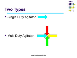
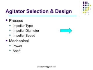
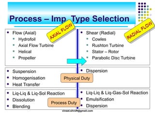
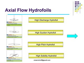
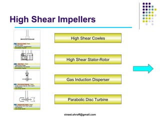
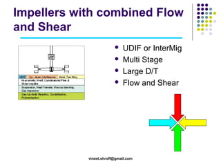
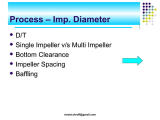
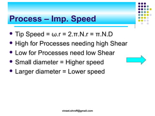
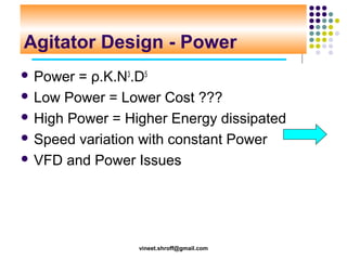
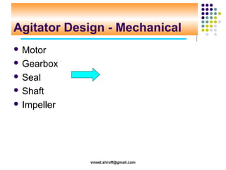
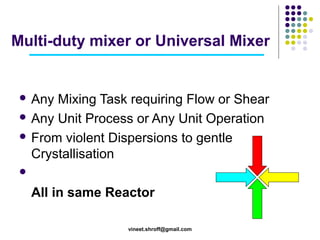
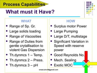
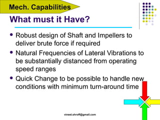
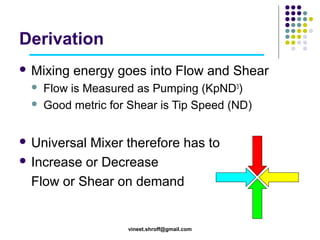
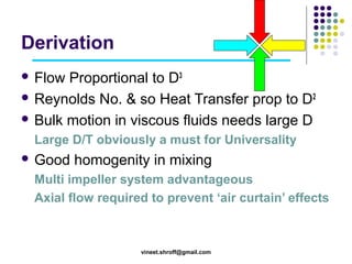
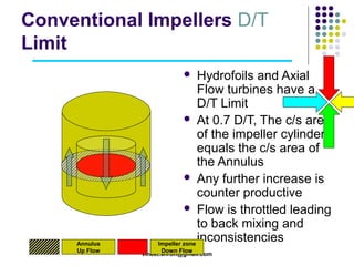
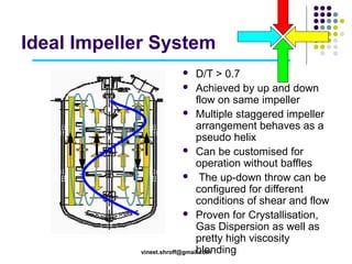
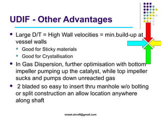
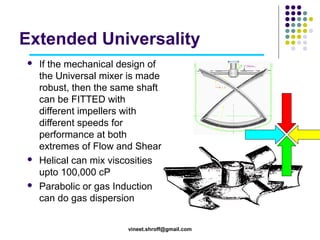
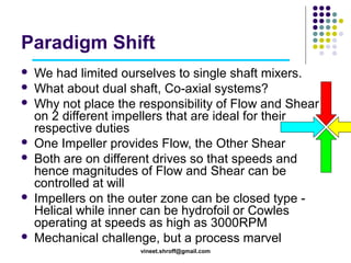
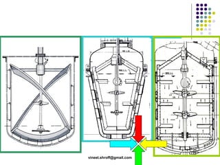
Agitator Design and
Selection
Standard Engineers

vineet.shroff@gmail.com
Food for Thought









You wanted to STIR THINGS UP But, your MIXING
gave only ‘AGITATION’.
There’s many a slip between the Plant and the Lab.
The Mixing arena is the Boxing ring where Chemist
and Chemical Engineer fight
In the work done for synthesising a Chemical
molecule, what % is the mass transfer, reaction and
mixing and what % is separation
Mixing can be demystified
vineet.shroff@gmail.com
Lecture Flow
 Single

duty Agitator
 Multi duty Agitator
 Films showing some Interesting Mixing
systems

vineet.shroff@gmail.com
Two Types
 Single

 Multi

Duty Agitator

Duty Agitator

vineet.shroff@gmail.com
Agitator Selection & Design
 Process




Impeller Type
Impeller Diameter
Impeller Speed

 Mechanical



Power
Shaft

vineet.shroff@gmail.com
Process – Imp. Type Selection
OW
LLOW
F
LLF
A
IA
X
AX I
A

OW
LLOW
F
LLF
IA
A
D
AD I
RA
R



Flow (Axial)
 Hydrofoil
 Axial Flow Turbine
 Helical
 Propeller



Shear (Radial)
 Cowles
 Rushton Turbine
 Stator – Rotor
 Parabolic Disc Turbine



Suspension
Homogenisation
Heat Transfer



Dispersion







Physical Duty

Liq-Liq & Liq-Sol Reaction
Dissolution
Process Duty
Blending





Liq-Liq & Liq-Gas-Sol Reaction
Emulsification
Dispersion

vineet.shroff@gmail.com
Axial Flow Hydrofoils
High Discharge Hydrofoil

High Suction Hydrofoil

High Pitch Hydrofoil

High Solidity Hydrofoil
vineet.shroff@gmail.com
High Shear Impellers
High Shear Cowles

High Shear Stator-Rotor

Gas Induction Disperser

Parabolic Disc Turbine

vineet.shroff@gmail.com
Impellers with combined Flow
and Shear





UDIF or InterMig
Multi Stage
Large D/T
Flow and Shear

vineet.shroff@gmail.com
Process – Imp. Diameter
 D/T
 Single

Impeller v/s Multi Impeller
 Bottom Clearance
 Impeller Spacing
 Baffling

vineet.shroff@gmail.com
Process – Imp. Speed
 Tip

Speed = ω.r = 2.π.N.r = π.N.D
 High for Processes needing high Shear
 Low for Processes need low Shear
 Small diameter = Higher speed
 Larger diameter = Lower speed

vineet.shroff@gmail.com
Agitator Design - Power
 Power

= ρ.K.N3.D5
 Low Power = Lower Cost ???
 High Power = Higher Energy dissipated
 Speed variation with constant Power
 VFD and Power Issues

vineet.shroff@gmail.com
Agitator Design - Mechanical
 Motor
 Gearbox
 Seal
 Shaft
 Impeller

vineet.shroff@gmail.com
Multi-duty mixer or Universal Mixer

 Any

Mixing Task requiring Flow or Shear
 Any Unit Process or Any Unit Operation
 From violent Dispersions to gentle
Crystallisation


All in same Reactor
vineet.shroff@gmail.com
When is it Needed?
 Change

in Product Specifications
 New R&D Results
 Change of Product
 New Regulations
There

are many unknowns in
modern day operations
vineet.shroff@gmail.com
Need 1

Change in Prod. Specs
Customers (Internal as well as External) are a Demanding Lot









Change in Particle Size (Increase / Decrease)
Different PSD
Higher Purity (bigger crystals with less ML)
Different Physical characteristics (colour, shape,
solution, emulsion, dispersion)
Additional step from downstream Processing
Different output Temperature
n
now
Many others …
Unk
vineet.shroff@gmail.com
Need 2

New R&D
Competiton, Cost Reduction and New Technologies
(ionic solvents, super acids, Green Chemistries,
surfactants, nanotechnologies) throw radical
possibilities of Process Intensification for
 Higher

Yield / Conversion
 Reduced by-Product formation
 Reduced Utility consumption
 Reduced batch cycle times
vineet.shroff@gmail.com

U

w
nkno

n
Need 3

Change of Product
Campaign based Production cycles demand
flexibility in capabilities
 New

Product
 Different Process
 Different operating conditions

U

w
kno
n

n

New Product Developed in the Lab or Pilot Plant
needs to be Produced on plant scale
 Unexpected

scale-up considerations
 Process modifications based on IP / quality
vineet.shroff@gmail.com
Need 4

New Regulations
Banned raw materials, stringent disposal norms
can impose variabilities
 Recipe

Change
 Change in operating conditions
 Change in Process

wn
n own
nk

U nkno
U
vineet.shroff@gmail.com
Process Capabilities

What must it Have?









WHAT
Range of Sp. Gr.
Large solids loading
Range of Viscosities
Range of Duties from
gentle crytallisation to
violent Gas Dispersion
Th.dynmcs 1 – Temp.
Th.dynmcs 2 – Press.
Th.dynmcs 3 – pH










HOW
Surplus motor Power
Large Pumping
Large D/T, multistage
Significant Variation in
Speed with reserve
power
Good Reynolds No.
Mech. Sealing
Exotic MOC

vineet.shroff@gmail.com
Mech. Capabilities

What must it Have?
 Robust

design of Shaft and Impellers to
deliver brute force if required
 Natural Frequencies of Lateral Vibrations to
be substantially distanced from operating
speed ranges
 Quick Change to be possible to handle new
conditions with minimum turn-around time

vineet.shroff@gmail.com
Derivation
 Mixing



energy goes into Flow and Shear

Flow is Measured as Pumping (KpND3)
Good metric for Shear is Tip Speed (ND)

 Universal

Mixer therefore has to
 Increase or Decrease
Flow or Shear on demand

vineet.shroff@gmail.com
Derivation
 Flow

Proportional to D3
 Reynolds No. & so Heat Transfer prop to D2
 Bulk motion in viscous fluids needs large D
Large D/T obviously a must for Universality
 Good

homogenity in mixing

Multi impeller system advantageous
Axial flow required to prevent ‘air curtain’ effects

vineet.shroff@gmail.com
Conventional Impellers D/T
Limit
Hydrofoils and Axial
Flow turbines have a
D/T Limit
 At 0.7 D/T, The c/s area
of the impeller cylinder
equals the c/s area of
the Annulus
 Any further increase is
counter productive
 Flow is throttled leading
to back mixing and
inconsistencies
Impeller zone


Annulus
Up Flow

Down Flow
vineet.shroff@gmail.com
Ideal Impeller System
D/T > 0.7
 Achieved by up and down
flow on same impeller
 Multiple staggered impeller
arrangement behaves as a
pseudo helix
 Can be customised for
operation without baffles
 The up-down throw can be
configured for different
conditions of shear and flow
 Proven for Crystallisation,
Gas Dispersion as well as
pretty high viscosity
blending
vineet.shroff@gmail.com

UDIF - Other Advantages


Large D/T = High Wall velocities = min.build-up at
vessel walls







Good for Sticky materials
Good for Crystallisation

In Gas Dispersion, further optimisation with bottom
impeller pumping up the catalyst, while top impeller
sucks and pumps down unreacted gas
2 bladed so easy to insert thru manhole w/o bolting
or split construction an allow location anywhere
along shaft
vineet.shroff@gmail.com
Extended Universality






If the mechanical design of
the Universal mixer is made
robust, then the same shaft
can be FITTED with
different impellers with
different speeds for
performance at both
extremes of Flow and Shear
Helical can mix viscosities
upto 100,000 cP
Parabolic or gas Induction
can do gas dispersion
vineet.shroff@gmail.com
Paradigm Shift











We had limited ourselves to single shaft mixers.
What about dual shaft, Co-axial systems?
Why not place the responsibility of Flow and Shear
on 2 different impellers that are ideal for their
respective duties
One Impeller provides Flow, the Other Shear
Both are on different drives so that speeds and
hence magnitudes of Flow and Shear can be
controlled at will
Impellers on the outer zone can be closed type Helical while inner can be hydrofoil or Cowles
operating at speeds as high as 3000RPM
Mechanical challenge, but a process marvel
vineet.shroff@gmail.com
Myths to be Shattered
 Lower

Motor Power means lower operating

cost
 Hydrofoils can do everything
 D/T to be around 1/3 to 0.4
 Mixer should be low capital cost.
 No option to GLR
 50Hz barrier
 Chemist and Chemical Engineer
vineet.shroff@gmail.com
Conclusion
 Decide

Single duty or Multi duty
 If Single duty - Decide Duty driver is Flow or
Shear
 Select impellers accordingly
 If Multi duty, large D/T, multi impeller, variable
speed.
 Ensure minimum hot spots (pH, temp.,
concentration)
vineet.shroff@gmail.com
Batch Crystalliser Mixer



Flow or Shear? Obviously Flow for larger crystals,
Shear for smaller
Impeller Type. – Anchor is the worst









Temperature gradient
Conc. Gradient
Grinding at bottom

Impeller Diameter.
Impeller speed
Multi Impeller
Mechanical – VFD.
vineet.shroff@gmail.com
In the end …
 Some

Films
 Video 1: Co-rotating Co-Axial Dispertron
 Thank

You
 Start Again

vineet.shroff@gmail.com

Agitator design and selection

  • 1.
    Agitator Design and Selection StandardEngineers vineet.shroff@gmail.com
  • 2.
    Food for Thought      Youwanted to STIR THINGS UP But, your MIXING gave only ‘AGITATION’. There’s many a slip between the Plant and the Lab. The Mixing arena is the Boxing ring where Chemist and Chemical Engineer fight In the work done for synthesising a Chemical molecule, what % is the mass transfer, reaction and mixing and what % is separation Mixing can be demystified vineet.shroff@gmail.com
  • 3.
    Lecture Flow  Single dutyAgitator  Multi duty Agitator  Films showing some Interesting Mixing systems vineet.shroff@gmail.com
  • 4.
    Two Types  Single Multi Duty Agitator Duty Agitator vineet.shroff@gmail.com
  • 5.
    Agitator Selection &Design  Process    Impeller Type Impeller Diameter Impeller Speed  Mechanical   Power Shaft vineet.shroff@gmail.com
  • 6.
    Process – Imp.Type Selection OW LLOW F LLF A IA X AX I A OW LLOW F LLF IA A D AD I RA R  Flow (Axial)  Hydrofoil  Axial Flow Turbine  Helical  Propeller  Shear (Radial)  Cowles  Rushton Turbine  Stator – Rotor  Parabolic Disc Turbine  Suspension Homogenisation Heat Transfer  Dispersion      Physical Duty Liq-Liq & Liq-Sol Reaction Dissolution Process Duty Blending    Liq-Liq & Liq-Gas-Sol Reaction Emulsification Dispersion vineet.shroff@gmail.com
  • 7.
    Axial Flow Hydrofoils HighDischarge Hydrofoil High Suction Hydrofoil High Pitch Hydrofoil High Solidity Hydrofoil vineet.shroff@gmail.com
  • 8.
    High Shear Impellers HighShear Cowles High Shear Stator-Rotor Gas Induction Disperser Parabolic Disc Turbine vineet.shroff@gmail.com
  • 9.
    Impellers with combinedFlow and Shear     UDIF or InterMig Multi Stage Large D/T Flow and Shear vineet.shroff@gmail.com
  • 10.
    Process – Imp.Diameter  D/T  Single Impeller v/s Multi Impeller  Bottom Clearance  Impeller Spacing  Baffling vineet.shroff@gmail.com
  • 11.
    Process – Imp.Speed  Tip Speed = ω.r = 2.π.N.r = π.N.D  High for Processes needing high Shear  Low for Processes need low Shear  Small diameter = Higher speed  Larger diameter = Lower speed vineet.shroff@gmail.com
  • 12.
    Agitator Design -Power  Power = ρ.K.N3.D5  Low Power = Lower Cost ???  High Power = Higher Energy dissipated  Speed variation with constant Power  VFD and Power Issues vineet.shroff@gmail.com
  • 13.
    Agitator Design -Mechanical  Motor  Gearbox  Seal  Shaft  Impeller vineet.shroff@gmail.com
  • 14.
    Multi-duty mixer orUniversal Mixer  Any Mixing Task requiring Flow or Shear  Any Unit Process or Any Unit Operation  From violent Dispersions to gentle Crystallisation  All in same Reactor vineet.shroff@gmail.com
  • 15.
    When is itNeeded?  Change in Product Specifications  New R&D Results  Change of Product  New Regulations There are many unknowns in modern day operations vineet.shroff@gmail.com
  • 16.
    Need 1 Change inProd. Specs Customers (Internal as well as External) are a Demanding Lot        Change in Particle Size (Increase / Decrease) Different PSD Higher Purity (bigger crystals with less ML) Different Physical characteristics (colour, shape, solution, emulsion, dispersion) Additional step from downstream Processing Different output Temperature n now Many others … Unk vineet.shroff@gmail.com
  • 17.
    Need 2 New R&D Competiton,Cost Reduction and New Technologies (ionic solvents, super acids, Green Chemistries, surfactants, nanotechnologies) throw radical possibilities of Process Intensification for  Higher Yield / Conversion  Reduced by-Product formation  Reduced Utility consumption  Reduced batch cycle times vineet.shroff@gmail.com U w nkno n
  • 18.
    Need 3 Change ofProduct Campaign based Production cycles demand flexibility in capabilities  New Product  Different Process  Different operating conditions U w kno n n New Product Developed in the Lab or Pilot Plant needs to be Produced on plant scale  Unexpected scale-up considerations  Process modifications based on IP / quality vineet.shroff@gmail.com
  • 19.
    Need 4 New Regulations Bannedraw materials, stringent disposal norms can impose variabilities  Recipe Change  Change in operating conditions  Change in Process wn n own nk U nkno U vineet.shroff@gmail.com
  • 20.
    Process Capabilities What mustit Have?        WHAT Range of Sp. Gr. Large solids loading Range of Viscosities Range of Duties from gentle crytallisation to violent Gas Dispersion Th.dynmcs 1 – Temp. Th.dynmcs 2 – Press. Th.dynmcs 3 – pH        HOW Surplus motor Power Large Pumping Large D/T, multistage Significant Variation in Speed with reserve power Good Reynolds No. Mech. Sealing Exotic MOC vineet.shroff@gmail.com
  • 21.
    Mech. Capabilities What mustit Have?  Robust design of Shaft and Impellers to deliver brute force if required  Natural Frequencies of Lateral Vibrations to be substantially distanced from operating speed ranges  Quick Change to be possible to handle new conditions with minimum turn-around time vineet.shroff@gmail.com
  • 22.
    Derivation  Mixing   energy goesinto Flow and Shear Flow is Measured as Pumping (KpND3) Good metric for Shear is Tip Speed (ND)  Universal Mixer therefore has to  Increase or Decrease Flow or Shear on demand vineet.shroff@gmail.com
  • 23.
    Derivation  Flow Proportional toD3  Reynolds No. & so Heat Transfer prop to D2  Bulk motion in viscous fluids needs large D Large D/T obviously a must for Universality  Good homogenity in mixing Multi impeller system advantageous Axial flow required to prevent ‘air curtain’ effects vineet.shroff@gmail.com
  • 24.
    Conventional Impellers D/T Limit Hydrofoilsand Axial Flow turbines have a D/T Limit  At 0.7 D/T, The c/s area of the impeller cylinder equals the c/s area of the Annulus  Any further increase is counter productive  Flow is throttled leading to back mixing and inconsistencies Impeller zone  Annulus Up Flow Down Flow vineet.shroff@gmail.com
  • 25.
    Ideal Impeller System D/T> 0.7  Achieved by up and down flow on same impeller  Multiple staggered impeller arrangement behaves as a pseudo helix  Can be customised for operation without baffles  The up-down throw can be configured for different conditions of shear and flow  Proven for Crystallisation, Gas Dispersion as well as pretty high viscosity blending vineet.shroff@gmail.com 
  • 26.
    UDIF - OtherAdvantages  Large D/T = High Wall velocities = min.build-up at vessel walls     Good for Sticky materials Good for Crystallisation In Gas Dispersion, further optimisation with bottom impeller pumping up the catalyst, while top impeller sucks and pumps down unreacted gas 2 bladed so easy to insert thru manhole w/o bolting or split construction an allow location anywhere along shaft vineet.shroff@gmail.com
  • 27.
    Extended Universality    If themechanical design of the Universal mixer is made robust, then the same shaft can be FITTED with different impellers with different speeds for performance at both extremes of Flow and Shear Helical can mix viscosities upto 100,000 cP Parabolic or gas Induction can do gas dispersion vineet.shroff@gmail.com
  • 28.
    Paradigm Shift        We hadlimited ourselves to single shaft mixers. What about dual shaft, Co-axial systems? Why not place the responsibility of Flow and Shear on 2 different impellers that are ideal for their respective duties One Impeller provides Flow, the Other Shear Both are on different drives so that speeds and hence magnitudes of Flow and Shear can be controlled at will Impellers on the outer zone can be closed type Helical while inner can be hydrofoil or Cowles operating at speeds as high as 3000RPM Mechanical challenge, but a process marvel vineet.shroff@gmail.com
  • 29.
  • 30.
    Myths to beShattered  Lower Motor Power means lower operating cost  Hydrofoils can do everything  D/T to be around 1/3 to 0.4  Mixer should be low capital cost.  No option to GLR  50Hz barrier  Chemist and Chemical Engineer vineet.shroff@gmail.com
  • 31.
    Conclusion  Decide Single dutyor Multi duty  If Single duty - Decide Duty driver is Flow or Shear  Select impellers accordingly  If Multi duty, large D/T, multi impeller, variable speed.  Ensure minimum hot spots (pH, temp., concentration) vineet.shroff@gmail.com
  • 32.
    Batch Crystalliser Mixer   Flowor Shear? Obviously Flow for larger crystals, Shear for smaller Impeller Type. – Anchor is the worst        Temperature gradient Conc. Gradient Grinding at bottom Impeller Diameter. Impeller speed Multi Impeller Mechanical – VFD. vineet.shroff@gmail.com
  • 33.
    In the end…  Some Films  Video 1: Co-rotating Co-Axial Dispertron  Thank You  Start Again vineet.shroff@gmail.com