
Recommended
More Related Content
What's hot
What's hot (20)
Similar to Floating Construction
Similar to Floating Construction (20)
More from vivatechijri
More from vivatechijri (20)
Recently uploaded
Recently uploaded (20)
Floating Construction
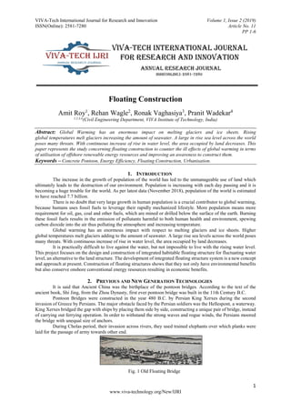
- 1. VIVA-Tech International Journal for Research and Innovation Volume 1, Issue 2 (2019) ISSN(Online): 2581-7280 Article No. 11 PP 1-6 1 www.viva-technology.org/New/IJRI Floating Construction Amit Roy1 , Rehan Wagle2 , Ronak Vaghasiya3 , Pranit Wadekar4 1,2,3,4 (Civil Engineering Department, VIVA Institute of Technology, India) Abstract: Global Warming has an enormous impact on melting glaciers and ice sheets. Rising global temperatures melt glaciers increasing the amount of seawater. A large in rise sea level across the world poses many threats. With continuous increase of rise in water level, the area occupied by land decreases. This paper represents the study concerning floating construction to counter the ill effects of global warming in terms of utilisation of offshore renewable energy resources and improving an awareness to construct them. Keywords – Concrete Pontoon, Energy Efficiency, Floating Construction, Urbanisation. 1. INTRODUCTION The increase in the growth of population of the world has led to the unmanageable use of land which ultimately leads to the destruction of our environment. Population is increasing with each day passing and it is becoming a huge trouble for the world. As per latest data (November 2018), population of the world is estimated to have reached 7.7 billion. There is no doubt that very large growth in human population is a crucial contributor to global warming, because humans uses fossil fuels to leverage their rapidly mechanized lifestyle. More population means more requirement for oil, gas, coal and other fuels, which are mined or drilled below the surface of the earth. Burning these fossil fuels results in the emission of pollutants harmful to both human health and environment, spewing carbon dioxide into the air thus polluting the atmosphere and increasing temperature. Global warming has an enormous impact with respect to melting glaciers and ice sheets. Higher global temperatures melt glaciers adding to the amount of seawater. A large rise sea levels across the world poses many threats. With continuous increase of rise in water level, the area occupied by land decreases. It is practically difficult to live against the water, but not impossible to live with the rising water level. This project focuses on the design and construction of integrated habitable floating structure for fluctuating water level, an alternative to the land structure. The development of integrated floating structure system is a new concept and approach at present. Construction of floating structures shows that they not only have environmental benefits but also conserve onshore conventional energy resources resulting in economic benefits. 2. PREVIOUS AND NEW GENERATION TECHNOLOGIES It is said that Ancient China was the birthplace of the pontoon bridges. According to the text of the ancient book, Shi Jing, from the Zhou Dynasty, first ever pontoon bridge was built in the 11th Century B.C. Pontoon Bridges were constructed in the year 480 B.C. by Persian King Xerxes during the second invasion of Greece by Persians. The major obstacle faced by the Persian soldiers was the Hellespont, a waterway. King Xerxes bridged the gap with ships by placing them side by side, constructing a unique pair of bridge, instead of carrying out ferrying operation. In order to withstand the strong waves and rogue winds, the Persians moored the bridge with unequal size of anchors. During Cholas period, their invasion across rivers, they used trained elephants over which planks were laid for the passage of army towards other end. Fig. 1 Old Floating Bridge
- 2. VIVA-Tech International Journal for Research and Innovation Volume 1, Issue 2 (2019) ISSN(Online): 2581-7280 Article No. 11 PP 1-6 2 www.viva-technology.org/New/IJRI With the Technological advancements, the design of floating construction has developed at a slow pace through the years catering to various individual needs. However in recent years, due to global energy crisis, the designs have become environmentally more aware. With proper design calculations, the floating constructions can be situated far away from the shores which can be connected to seabed with proper mooring technology, so that it does not get float away during the times of flood and with proper connection can even help the structure to rise or fall with the rise or fall in water level during low and high tides. In general, floating mechanism can be broadly classified into two categories which are floating on the liquid and floating on the air. For this research paper purpose, the investigation will be carried out on the floating mechanism for the structure to float on water. The most vital parameter for a floating construction is the weight of the structure which it needs to carry. The buoyant force or lift capacity of the pontoon must be greater than the weight of the structure including the self-weight of the pontoon. Fig. 2 Floating Pontoon Floating structures are connected with the shore line so that fresh water can be brought straight into the residential units and sewage can be pumped back into sewer lines. 3. ENERGY EFFICIENCY OPPORTUNITIES Considering global energy crisis, ocean and sea energy can prove to be producing a great deal of profit. There are three main types of energy resources which can be obtained from sea. Those are, tidal energy, wave energy and sea thermal energy. Energy obtained from sea has the advantage of being clean, pollution free and it is renewable which is of great practical significance to improve our ecosystem and help us fight climate change, conserve onshore energy and reduce the effect of global warming. In addition to three renewable energy sources mentioned above, offshore winds can also be considered as a clean source of ocean energy. The kinetic energy of the moving air above seas and ocean can be controlled and make use of with the provisions of wind turbines. Offshore winds are comparatively stronger and steadier than the offshore winds. Wave energy is also one of the main energy sources that has the potential to address growing concerns of global energy crisis and produce huge amount of energy over other renewable energy sources. It is an irregular and oscillating low frequency that can be easily converted to a 60 Hertz frequency which can then be added to electricity utility grid. There are basically three methods to harness wave energy: Float or buoy systems that use the rise and fall of ocean expands to drive hydraulic pumps. The device can be mounted to a floating raft or to an arrangement fixed on the ocean floor. A series of moored buoys rise and fall with the waves. The movement smacks an electrical generator and makes electricity that is then sent ashore by underwater power cable. Oscillating water column are those devices in which the in-and-out motion of waves at the shoreline enters the water column and force air to rotate a turbine. The column fills with water as the wave rises and empties as it falls. In this process, air inside the column gets compressed and heats up, thus creating energy as a piston does. That energy is then collected and sent to shore by electrical cable. Tapered channel system, lean on a shore-mounted structure to channel and centralize the waves, steering them into an elevated reservoir. Water flowing out of this reservoir is used to generate electricity, using standard hydropower automation. 4. SUPERSTRUCTURE The Superstructure can be designed by both using combination of structural steel and reinforced concrete or reinforced concrete alone. Superstructure can also be designed using Prefabricated building materials that are manufactured offsite and shipped later to assemble at the final location. Some of the commonly used prefabricated
- 3. VIVA-Tech International Journal for Research and Innovation Volume 1, Issue 2 (2019) ISSN(Online): 2581-7280 Article No. 11 PP 1-6 3 www.viva-technology.org/New/IJRI building materials are aluminium, steel, wood, fiberglass and concrete. Depending upon the type of structure and load it needs to carry, the superstructure materials can be decided. Fig. 3 Floating House Conventional floating houses, normally houseboats, have been built in various countries in the places vulnerable to floods, near seashore and on the lakes and rivers. In Australia, on the Murray River and along the coastline of Queensland, there are many vehicular device equipped pontoon based houseboats with more than just a bed room, some even having multi-storeyed structure. Houseboats can also be found in Lake Eldon in Victoria and in Hawkesbury River near Sydney. Floating houses, as of now are constructed which float only during floods. Thus, there are two broad type of floating construction, one which float endlessly and other that float only during flood waters else get placed on ground, particularly during dry season when there is no water. There are two general basic principles for making floating houses. First is the pontoon principle, in which a solid platform is constructed which is lighter than the surrounding water and the other is based on the ship or boat in which a hollow concrete box is created which is kept open at the top. The pontoon principle has the benefit of its use in shallow water as well as in deep water, compared to the hollow concrete box which has the benefit of higher space utilization within as a part of the construction. Both type of floating houses are connected with a flexible connection to the dock, so the houses can rise and fall with the water during high tides and during low tides. When required the floating construction can also be moved elsewhere at short notice without causing any damage to the environment. The superstructure of the floating construction in consideration has been designed as a composite structure, with slabs designed with RCC of grade M25 and beams and columns of steel sections, which has to transmit a factored load 7014kN. 5. FLOATING COMPARTMENT The floating compartment is a watertight vessel where buoyancy is required in water, which is inflatable to support a bridge or a temporary or mobile structure. The pontoons can be made up of different materials, each having its own advantages and disadvantages and type of structure or intensity load to be carried. Fiberglass Pontoon: Fiberglass is used as a construction substance for the hulls of many boats as it is a flimsy and fairly long-lasting material. It is not subject to rust. If the pontoons are punctured or harmed, and require repairs, the cost of repairing them can be quite expensive. It is equitably durable, but cannot carry heavy loads. Foam filled Pontoon: The big benefit with foam filled pontoon is that they are not hollow, so they cannot leak. They are also usually inexpensive to manufacture, as they typically have a plastic exterior and don’t require a thick and protective casing to shield an empty interior. Foam filled pontoons typically have to be fairly small, as the wider they get, the lower the pontoon sits in the water, which leads to more pull. Steel Pontoon: Many antiquated pontoon boats were made using steel, as it is a cheaper substance. The big benefit to steel pontoons is that they are almost always used. The big drawback of steel for pontoon is that steel is a corrosive material, and it will become rusty over time when exposed to moisture and air. This leads to leaks and cracks, which requires persistent maintenance and may require substantial repairs. It can carry heavy loads. Concrete Pontoon: Concrete pontoons stand out in contradistinction to other pontoons for its firmness and imperishability. The concrete pontoons are filled with foam plastic which is then covered from all sides with concrete. The pontoons made up of concrete are designed to last for 40-50 years when compared with the pontoons which are lighter in weight and are made up of wood, for its functioning in harsh environmental conditions. The pontoons constructed from concrete and Styrofoam achieves a high
- 4. VIVA-Tech International Journal for Research and Innovation Volume 1, Issue 2 (2019) ISSN(Online): 2581-7280 Article No. 11 PP 1-6 4 www.viva-technology.org/New/IJRI level of buoyancy along with high degree of stability thus making it practically unsinkable. The constructed pontoon structure has insignificant effect on the built environment as well as on the aquatic life and has low to zero maintenance. Fig. 3: Floating Compartment The floating compartment or pontoon consists of top slab, concrete walls and bottom slab. The entire size of the pontoon depends upon the area of the structure resting above as well as the maximum load likely to act upon it. The overall construction of the pontoon involves setting of wall forms, rebars, and installation of post- tensioning ducts; setting of wall forms for internal concrete walls; pouring of concrete for both exterior as well as interior concrete walls; installation of rebars of top slab and post tensioning ducts; pouring of top slab concrete and lastly removal of wall forms and perform post tensioning to add strength to the top slab. 6. FORCE OF BUOYANCY The upward thrust exerted by the fluid on the body when immersed is known as force of buoyancy or buoyant force or simply buoyancy. This upward force acting on the body is equal to the weight of the fluid displaced by the body. The principle of buoyancy discovered by ancient Greek Mathematician, Archimedes states that, any body whether entirely or partly submerged in a fluid (liquid or gas) at rest is acted upon by an upward force, which is equal to the magnitude of the weight of the fluid displaced by the body, acting at the centre of mass. For example, when a ship is launched into an ocean, it sinks, until the weight of the water it displaces is equal to the weight of the body. An object is more buoyant in salt water than it is in fresh water. This is because, the dissolved salts in water increases its density or its mass per unit volume. The salt already present in sea water or in ocean, reacts with the water molecules, thus forming a polar bond. As per Archimedes principle, the upward push acting on the submerged body is equal to the weight of the water displaced by the body acting at the centre of mass. The density of sea water is 10.3 kN/m3 whereas that of ordinary water is 10 kN/m3. Table 1: Calculation of Buoyant Force Units L (m) B (m) H (m) Unit Weight (kN/m3 ) Service Load (kN) Load from Structure - - - - 4676 Pontoon Top Slab (Dead Wt.) 60 45 0.775 25 11508.75 Pontoon Top Slab (Imposed Wt.) 60 45 0.775 5.5 14850 Pontoon Bottom Slab 60 45 0.700 25 47250 Shear Walls 175.139 7.000 25 30649.33 Total 146396.6
- 5. VIVA-Tech International Journal for Research and Innovation Volume 1, Issue 2 (2019) ISSN(Online): 2581-7280 Article No. 11 PP 1-6 5 www.viva-technology.org/New/IJRI The volume of cavity inside the pontoon as calculated is found to be 17674.03m3. Total weight of water being replaced by air is calculated to be 173382.2kN which is greater than the total load acting downwards including self-weight of the pontoon by 26985.6kN. This force known as the uplift force or the buoyant force will help the floating construction afloat on water. 7. DEGREE OF FLOATING STABILITY Density plays a crucial role in Archimedes Principle because of the fact that, density of the object will be the ultimate determination factor whether an object will float or sink. A submerged body or floating body is said to be stable if it comes back to its original position after a slight disturbance. The positions of centre of gravity and centre of buoyancy are key terms in determining the stability of a floating body. For the floating structure, structural stability is very important to prevent failure of the structure caused by overturning due to angular displacement. For the study of floating stability of a structure, it is very important to determine the positions of the various forces acting upon the structure. Stability can be defined as the extent to which an object to return to the stable equilibrium position. The stability is calculated first by determining the centre of buoyancy, which also happens to be the centre of the volume of the submerged part of floating construction. The extent to which the buoyancy centre (FB) moves in a certain angle depends on the width of the float base. The wider the float base, the small the shifting distance of the buoyancy centre (B) will be from the centre. When the body is given a small angular displacement, its starts oscillating about a point known as the Meta-Centre. The distance between the meta-centre of a floating body and the centre of gravity of a floating body is called meta-centric height. The lower the centre of gravity the greater is the distance between centre of gravity and meta-centre. This leads to more stable structure. Fig. 4 Meta-centric height for a cubical floating body The expression for the Meta-centric height, GM is, Meta-centric height, GM = I/V - CG where, I = Moment of Inertia; V = Volume; CG = Centre of Gravity The meta-centric height for the floating structure is calculated as 28.265m. Basically, floating house model is to be able to have at least 500mm above the water surface when it is fully loaded. The buffer height of 500mm above water surface is to cater for any miscellaneous loading added which might cause the structure to be just above the water surface. The idea of buffer height of 500mm above water surface is to prevent the water from spreading onto the slab. As referred to the target of having at least 500mm height above the water surface as discussed, this height is evaluated as below: Height above water surface = [(26985.6 x 1000)/9.81] / (1000 x 60 x 45) = 1.018m = 1018mm 8. SCOPE AND LIMITATION Scope: A floating construction is comparatively cheaper than a construction on land It can achieve significant energy savings everyday Different modules are readily available for quick assemble Installation process is lucid Suitable for all types of water including oceans Size variance is possible Excellent Stability of the structure with proper design considerations. Requires maintenance on rarely basis. Limitation: Mooring Connector technology is still experimental
- 6. VIVA-Tech International Journal for Research and Innovation Volume 1, Issue 2 (2019) ISSN(Online): 2581-7280 Article No. 11 PP 1-6 6 www.viva-technology.org/New/IJRI The cost of construction is high Skilled labours are required High end equipments are required for construction of floating structures, which ultimately increases the cost of project 9. CONCLUSION This paper analysed a brief description of the construction of floating structures and energy resources produced by tides, waves and offshore winds. Construction of floating structures shows that they do not only possess environmental benefits but also utilizes offshore renewable energy resources resulting in economic benefits. The design must be carried out using light weight construction stuffs and the entire structure must have a stable arrangement. This paper presented that floating construction can be an interesting way to combine offshore energy resources and floating architecture. This forthcoming technology will be in application in many parts of the world, when the existing land surface will be taken away with the rising water level, which is ill effect of rapid increasing population and global warming. This paper not only discussed about the concept of floating structures but also encouraged to use offshore energy resources. REFERENCES [1] A. Ambica and K. Venkatraman, “Floating Architecture: A Design on Hydrophilic Floating House for Fluctuating Water Level”, Vol. (8)32, ISSN: 0974-6846, 2017. [2] D. Johnson Victor “Essentials of Bridge Engineering”, Sixth Edition. [3] Geir Moe, “Design philosophy of floating bridges with emphasis on ways to ensure long life”, Journal of Marine Science and Technology (1997) 2:182-189. [4] M. Hari Sathish Kumar, E. Saravanan, S, Manikandan, S. Akash Kumar, “DESIGN OF FLOATING BRIDGE CROSS OVER”, Vol. (4), ISSN: 2395-0056, 2017. [5] R.M. Manoj Kumar, J. Amit Binglesh, “ECONOMICAL DESIGN OF FLOATING BRIDGES”, Vol. (12), ISSN: 0976-1353, 2015. [6] Shahryar Habibi, “Floating Building Oppurtunities For Future Sustainable Development And Energy Efficiency Gains”, Habibi, J Archit Eng Tech 2015. [7] N. Krishna Raju, “Design of Bridges”, Fourth edition. [8] Dr. V.L. Shah, Late Dr. S.R. Karve, “Limit State Theory and Design of Reinforced Concrete”, Eighth Edition. [9] Dr. R.K. Bansal, “A textbook of Fluid Mechanics and Hydraulic Machines”, Revised Ninth Edition. [10] S.K. Duggal, “Limit State Design of Steel Structures”, Second Edition. [11] P.C. Varghese, “Limit State Design of Reinforced Concrete”, Second Edition.