Downloaded 1,557 times


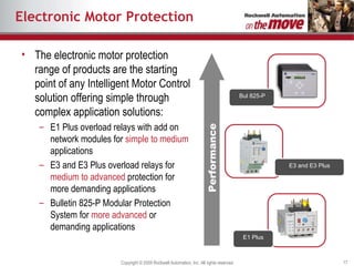
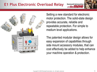
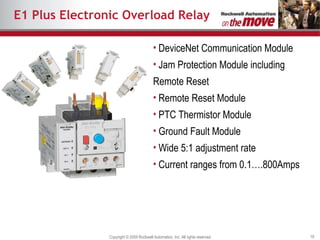
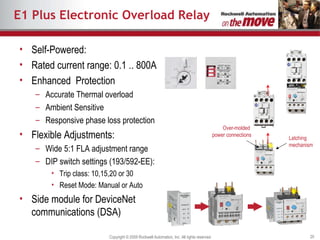
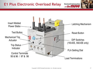
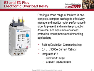
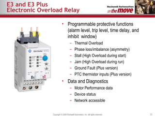
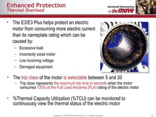


The document discusses motor overload protection and failure prevention. It describes how motors are critical to industry and fail primarily due to excessive heat from overloading. Electronic motor protection devices like the E1 Plus, E3, and E3 Plus overload relays provide accurate thermal overload protection, phase loss protection, and other advanced features to prevent motor failures and reduce downtime. They offer enhanced monitoring and protection compared to traditional overload relays.


