Tembisa Central Terminating Pills +27838792658 PHOMOLONG Top Abortion Pills F...
1.1Load Flow.pdf
1. ETAP Workshop Notes
Load Flow Analysis
This document is confidential and proprietary to ETAP / ETAP Automation and may not be reproduced, published or disclosed to others
without written authorization of ETAP / ETAP Automation. All Rights Reserved. Page 1 of 21
Purpose and Description
The purpose of this exercise is to perform load flow analysis/ power flow analysis on a double-
ended normally open tie power system. Power factor improvement and power sharing between
sources of power system & Transformer MVA sizing program will also be illustrated using an
example.
Procedure
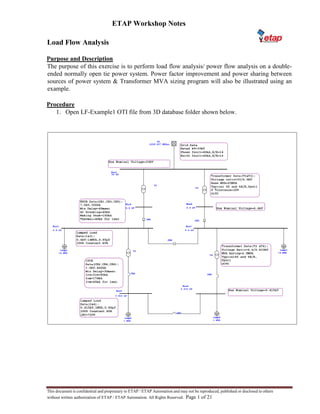
1. Open LF-Example1 OTI file from 3D database folder shown below.
2. ETAP Workshop Notes
Load Flow Analysis
This document is confidential and proprietary to ETAP / ETAP Automation and may not be reproduced, published or disclosed to others
without written authorization of ETAP / ETAP Automation. All Rights Reserved. Page 2 of 21
2. In the rating page of Power Grid, Various Generation categories are defined as shown
below.
3. To rename the default generation categories, click on the Project menu, go to Settings and
select Generation Categories as shown below.
4. Delete pre-existing names & give the user defined names for Generation Categories as
shown below.
5. Similarly, repeat the above steps to rename the loading categories as Peak Load, Normal
Load and Minimum Load.
3. ETAP Workshop Notes
Load Flow Analysis
This document is confidential and proprietary to ETAP / ETAP Automation and may not be reproduced, published or disclosed to others
without written authorization of ETAP / ETAP Automation. All Rights Reserved. Page 3 of 21
6. Double click on Power Grid, go to Rating page and enter following data in %V column for
respective Generation Categories.
7. Double click on Lumped Load, go to Nameplate page and enter following data in % loading
column for respective Loading Categories.
8. To create a new study case, click on “New Study case” with the name Peak LFC as shown
below.
4. ETAP Workshop Notes
Load Flow Analysis
This document is confidential and proprietary to ETAP / ETAP Automation and may not be reproduced, published or disclosed to others
without written authorization of ETAP / ETAP Automation. All Rights Reserved. Page 4 of 21
9. Select the study case Peak LFC using drop down menu and go to loading page. Select
Loading Category as Peak Load and Generation Category as Minimum GV.
10. Go to Alert page of Peak LFC load flow study case and uncheck the option for marginal
alerts.
11. Use default options for all other options in the Info page, Loading page, Adjustment page
and Alert page of the load flow study case.
12. Select single out configuration from Configuration Manager drop down button.
13. Construct two more load flow study cases using matrix given below.
Load Flow Study Case matrix
Study Case
Name
Generation
Category
Loading
Category
Configuration
Marginal
Alerts
Peak LFC Minimum GV Peak Load Single out Off
Normal LFC Normal GV Normal Load Normal Off
Minimum
LFC
Maximum GV
Minimum
Load
Normal Off
14. Add following data according to each study case in Study remarks section available on the
Info page of the Load Flow Study Case.
Study Case
Name
Study Remarks
Peak LFC Load = Peak, Configuration = Single Out, Grid = 90%V
Normal LFC Load = Normal, Configuration = Normal, Grid = 100%V
Minimum LFC Load = Minimum, Configuration = Normal, Grid = 110%V
New Study
Case
Edit Study
Case
5. ETAP Workshop Notes
Load Flow Analysis
This document is confidential and proprietary to ETAP / ETAP Automation and may not be reproduced, published or disclosed to others
without written authorization of ETAP / ETAP Automation. All Rights Reserved. Page 5 of 21
15. Select Peak LFC study case using drop down menu and select the output report name as
‘Prompt’.
Peak Load Flow results
16. Run Load Flow as shown below.
17. Edit the output file name to ‘Peak LFC’.
Run Load
Flow
6. ETAP Workshop Notes
Load Flow Analysis
This document is confidential and proprietary to ETAP / ETAP Automation and may not be reproduced, published or disclosed to others
without written authorization of ETAP / ETAP Automation. All Rights Reserved. Page 6 of 21
18. Change the Transformer tap range of T1& T3 from +10 to +12.5 for maximum tap range
& -10 to -12.5 for minimum tap range and run Peak LFC.
19. Similarly run other two load flow study case and generate following load flow reports as
per study case.
Study Case Name Output Report Name
Peak LFC Peak LFC
Normal LFC Normal LFC
Minimum LFC Minimum LFC
7. ETAP Workshop Notes
Load Flow Analysis
This document is confidential and proprietary to ETAP / ETAP Automation and may not be reproduced, published or disclosed to others
without written authorization of ETAP / ETAP Automation. All Rights Reserved. Page 7 of 21
Normal Load Flow Results
Minimum Load Flow Results
8. ETAP Workshop Notes
Load Flow Analysis
This document is confidential and proprietary to ETAP / ETAP Automation and may not be reproduced, published or disclosed to others
without written authorization of ETAP / ETAP Automation. All Rights Reserved. Page 8 of 21
20. Adjust the tap position of Transformers T2 & T4 as shown.
21. Run all the load flow cases and check for the alerts.
22. Click on display options and check the effect of following options.
• Units: To see units display in load flow.
• Select kW, jkvar display in k or Mega.
• Select KVA, PF display in k or Mega.
• Select A, PF display in k or Mega.
• Select branch losses. Select bus angle.
9. ETAP Workshop Notes
Load Flow Analysis
This document is confidential and proprietary to ETAP / ETAP Automation and may not be reproduced, published or disclosed to others
without written authorization of ETAP / ETAP Automation. All Rights Reserved. Page 9 of 21
23. Create following scenarios using Scenario Wizard
Scenario Name Configuration Load Flow Case Output Report Name
Peak LF Single Out Peak LFC Peak LFC
Normal LF Normal Normal LFC Normal LFC
Minimum LF Normal Minimum LFC Minimum LFC
24. Check the results of different load flow scenarios created using Scenario Wizard against
results obtained earlier using load flow calculation.
10. ETAP Workshop Notes
Load Flow Analysis
This document is confidential and proprietary to ETAP / ETAP Automation and may not be reproduced, published or disclosed to others
without written authorization of ETAP / ETAP Automation. All Rights Reserved. Page 10 of 21
Power Factor Improvement Capacitors
Purpose and Description
The purpose of this exercise is to improve 33 kV grid power factor to 95% - 100% for all load flow
cases.
Capacitor location- 6.6 kV Buses No. of stages
• Stage 1 for Minimum load flow
• Stage 2 for Normal & Peak load flow
Procedure
Procedure for stage 1 – Power Factor Improvement for Minimum Load Flow
1. Run Minimum Load Flow.
2. Check the PF at the 6.6 kV bus and transformer incomer Bus1. Hint – Change the display
options in load flow to check MVA/kVA and power factor.
3. Add the difference between power factor at Bus2 and Bus1 to desired pf of 95%.
4. Connect a harmonic filter to Bus3.
5. Double click on Harmonic Filter, go to Parameter page and click on Size Filter.
6. In Size filter page enter following parameters and click on Size Filter button.
11. ETAP Workshop Notes
Load Flow Analysis
This document is confidential and proprietary to ETAP / ETAP Automation and may not be reproduced, published or disclosed to others
without written authorization of ETAP / ETAP Automation. All Rights Reserved. Page 11 of 21
Note
• Load MVA is taken as the MVA load supplied by 33/6.9 kV transformer secondary
side.
• Desired PF = 95 + (PF of Bus2 – PF of Bus1).
7. After Sizing the filter, substitute the values using the Substitute button available on the
Harmonic Filter Sizing page.
8. In Parameter page of the Harmonic Filter enter Inductor Q factor as 30 as shown below.
12. ETAP Workshop Notes
Load Flow Analysis
This document is confidential and proprietary to ETAP / ETAP Automation and may not be reproduced, published or disclosed to
others without written authorization of ETAP / ETAP Automation. All Rights Reserved. 12 of 21
Note
• ETAP requests for fundamental frequency Q that is Q1 for the Inductor L1 of
Harmonic Filter.
• Q factor is X/R of coil (inductor)
At tuned value, Qtuned =htuned × XL1
R
Where XL1 is reactance in ohm of reactor at fundamental then
Qtuned = (htuned × Q1) … Q1= XL1
R
Q1= Qtuned
htuned
(Q tuned is usually 30, 60, 100 or 175)
9. Copy the harmonic filter connected to Bus3 and paste it on Bus7.
10. Run the minimum load flow again to check that the power factor at the Bus1 is more than
95%.
Procedure for stage 2 – Power Factor Improvement for Normal and Peak Load Flow
1. Run the normal load flow with stage 1 filters ON.
2. Check if PF at Bus2 or Bus1 is below 95%.
3. Check the PF at the Bus2 and transformer incomer i.e. Bus1. Hint – Change the display
options in load flow to check MVA/kVA and pf.
4. Add the difference between power factor at Bus2 and Bus1 to desired pf of 98%.
5. Add an additional harmonic filter to Bus3.
6. Double click on Harmonic Filter, go to Parameter page and click on Size Filter.
13. ETAP Workshop Notes
Load Flow Analysis
This document is confidential and proprietary to ETAP / ETAP Automation and may not be reproduced, published or disclosed to
others without written authorization of ETAP / ETAP Automation. All Rights Reserved. 13 of 21
7. In Size filter page, enter following parameters and click on Size Filter button.
Note:
Desired PF = 98 + (PF of Bus2 –PF of Bus1). But the value used is 100% as this will
be helpful in Peak load flow case as well.
8. After Sizing the filter substitute the values using the Substitute button available on the
Harmonic Filter Sizing page.
9. In Parameter page of the Harmonic Filter enter Inductor Q factor as 30 as shown below.
14. ETAP Workshop Notes
Load Flow Analysis
This document is confidential and proprietary to ETAP / ETAP Automation and may not be reproduced, published or disclosed to
others without written authorization of ETAP / ETAP Automation. All Rights Reserved. 14 of 21
10. Run Normal and Peak Load Flow with stage 1 and stage 2 harmonic filters to check the
power factor at 33kV bus is more than 95%.
11. Run the Minimum load flow with stage 1 and stage 2 harmonic filters and check the power
factor at 33 kV bus.
Hint – Is it required to use the harmonic filter in stage 2 for Minimum Load Flow case?