
Recommended
Recommended
More Related Content
Viewers also liked
Similar to Load Match Taco Hss
Similar to Load Match Taco Hss (20)
More from kiakaha
More from kiakaha (20)
Recently uploaded
Recently uploaded (20)
Load Match Taco Hss
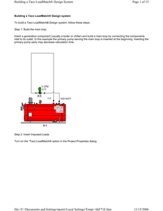
- 1. Building a Taco LoadMatch® Design System Page 1 of 15 Building a Taco LoadMatch® Design system To build a Taco LoadMatch® Design system, follow these steps: Step 1: Build the main loop Insert a generation component (usually a boiler or chiller) and build a main loop by connecting the components inlet to its outlet. In this example the primary pump serving the main loop is inserted at the beginning. Inserting the primary pump early may decrease calculation time. Step 2: Insert Imposed Loads Turn on the quot;Taco LoadMatch® option in the Project Properties dialog. file://C:Documents and SettingsrpuririLocal SettingsTemp~hhF71E.htm 11/15/2006
- 2. Building a Taco LoadMatch® Design System Page 2 of 15 Insert an Imposed Load (or other load type). Connect to the supply side of the main loop first. Connect the Imposed load input to the primary loop second (short-cut). Piping displayed black in the example below will remain black until the system is complete (load data is entered). file://C:Documents and SettingsrpuririLocal SettingsTemp~hhF71E.htm 11/15/2006
- 3. Building a Taco LoadMatch® Design System Page 3 of 15 Step 3: Enter load data Enter a numerical load value for each imposed load (automatically calculated for airside load components). Load information is usually obtained from a load program such as CHVAC (www.elitesoft.com). Double left-click on each Imposed Load and enter a load for the appropriate season. For information regarding speeding up data entry see the help topic, simultaneous data entry. file://C:Documents and SettingsrpuririLocal SettingsTemp~hhF71E.htm 11/15/2006
- 4. Building a Taco LoadMatch® Design System Page 4 of 15 Step 4: Set the main loop fluid temperature Set the main loop fluid temperature and flow rate. Double-click the generation component, choose the quot;Fluidquot; tab and set both the entering and leaving temperatures. Altering the leaving temperature will set the flow in the main loop. Avoid setting the main loop temperature incorrectly. file://C:Documents and SettingsrpuririLocal SettingsTemp~hhF71E.htm 11/15/2006
- 5. Building a Taco LoadMatch® Design System Page 5 of 15 Step 5: Set the Imposed Load fluid temperature Imposed loads may represent a variety of components such as fan coils or terminal units. To closely model a specific piece of equipment it may be necessary to adjust the fluid temperature change. Because adjustments to upstream components affect downstream components it is recommend that the user adjust the Imposed Loads closest to the boiler and then work downstream. Note: It is strongly recommended that the temperature change option be used instead of adjusting the leaving temperature of each Imposed Load. file://C:Documents and SettingsrpuririLocal SettingsTemp~hhF71E.htm 11/15/2006
- 6. Building a Taco LoadMatch® Design System Page 6 of 15 Step 6: Enter head loss data Enter the head loss data associated with each component in the system. This includes head loss data for Imposed Loads; usually a single maximum value for all Imposed Loads will suffice. file://C:Documents and SettingsrpuririLocal SettingsTemp~hhF71E.htm 11/15/2006
- 7. Building a Taco LoadMatch® Design System Page 7 of 15 For head losses associated with pipes enter the specific pipe. It is not necessary to enter pipe length for every single pipe in the system rather enter critical pipe length in a single typical location in each loop. By default a length of 30 feet is automatically entered on the pipe between the pump and the load. This length should suffice for most systems but should be overridden if required. file://C:Documents and SettingsrpuririLocal SettingsTemp~hhF71E.htm 11/15/2006
- 8. Building a Taco LoadMatch® Design System Page 8 of 15 Step 7: Select components Select equipment that matches the component design criteria. file://C:Documents and SettingsrpuririLocal SettingsTemp~hhF71E.htm 11/15/2006
- 9. Building a Taco LoadMatch® Design System Page 9 of 15 The following represents a simple version of a completed Taco LoadMatch® Design: file://C:Documents and SettingsrpuririLocal SettingsTemp~hhF71E.htm 11/15/2006
- 10. Building a Taco LoadMatch® Design System Page 10 of 15 Note: Additional example files are available in the example directory. Step 8: Print out schedules Once the design is complete schedules of the final equipment selections may be printed. See the Schedule printing section for more information on this topic. Some automated tasks included in the Taco LoadMatch® design option are: The pipe length between the LoadMatch® pump and the load automatically assumes a length of 30 feet to simulate the total length of pipe in the LoadMatch® circuit. The LoadMatch® pump automatically assumes as part of its ID the load ID. Taco LoadMatch® Design option The Taco LoadMatch® option is enabled by opening the Project Properties dialog (double-left click the white screen). When enabled, Taco pumps and Taco twin tees are automatically inserted when connecting loads to the primary loop. Using the this feature assists in the design of Taco LoadMatch® systems. file://C:Documents and SettingsrpuririLocal SettingsTemp~hhF71E.htm 11/15/2006
- 11. Building a Taco LoadMatch® Design System Page 11 of 15 Incorrect LoadMatch® example If leaving temperature of the load and generation are unmatched the system will be incorrect as in the following example: file://C:Documents and SettingsrpuririLocal SettingsTemp~hhF71E.htm 11/15/2006
- 12. Building a Taco LoadMatch® Design System Page 12 of 15 This system unmatched because: The boiler entering fluid temperature has been forced to 140°F to force a flow in the main loop The lowest load leaving fluid temperature is 170°F Results of this mismatch will be: The main loop piping will be undersized The main loop pump will be undersized This system may be corrected by: Un-checking the boiler leaving fluid temperature box to calculate the minimum system return temperature file://C:Documents and SettingsrpuririLocal SettingsTemp~hhF71E.htm 11/15/2006
- 13. Building a Taco LoadMatch® Design System Page 13 of 15 Re-checking the boiler leaving fluid temperature box and set it above the optimum return temperature file://C:Documents and SettingsrpuririLocal SettingsTemp~hhF71E.htm 11/15/2006
- 14. Building a Taco LoadMatch® Design System Page 14 of 15 The result is a corrected system: file://C:Documents and SettingsrpuririLocal SettingsTemp~hhF71E.htm 11/15/2006
- 15. Building a Taco LoadMatch® Design System Page 15 of 15 The boiler flow has been corrected from 3.7 GPM to 14.8 GPM. file://C:Documents and SettingsrpuririLocal SettingsTemp~hhF71E.htm 11/15/2006