Max. shear stress theory-Maximum Shear Stress Theory Maximum Distortional ...
Rectifiers.pptx
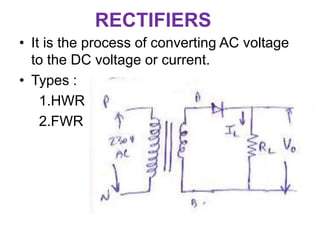
1. RECTIFIERS
• It is the process of converting AC voltage
to the DC voltage or current.
• Types :
1.HWR
2.FWR
2.
3. OPERATION :
• During positive half cycle A is positive with
respect to B. Hence diode is forward biased
and starts conducting.
• During negative half cycle B is positive with
respect to A. Hence diode is reverse biased
and do not conducts.
4. ANALYSIS OF HWR
• Average Load current (ILDC )
The average value of periodic function is
given by the area under one cycle of the function
divided by the base function.
7. 4.RMS or AC Load Voltage (VLRMS )
VLRMS = ILRMS * RL
VLRMS =
𝑽𝒎
𝟐
5.Voltage Regulation :
Ideally the average rectifier output should
remains constant. But practically it varies with
the change in load current.
10. Ripple factor (ϒ)
• The rectifier output consists of AC as well as
DC components. The ripple factor measures
the percentage of AC component in the
rectifier output.
ϒ =
𝑉𝐴𝐶
𝑉𝐷𝐶
• ϒ =1.21
• %ϒ =121
11. • Transformer Utilization Factor :
It is defined as the ratio of DC output power
to the AC power ratings of transformer.
Disadvantages of HWR :
High ripple factor
Low rectification efficiency
Low TUF
Low DC output voltage and current
It required large filter component.
12. FWR USING CENTRE TAPPED
TRANSFORMER
• A circuit which converts the AC
voltage/current into pulsating voltage/current
during both the half cycle of input is called as
FWR.
13.
14. Analysis of FWR
• Average Load current (ILDC )
The average value of periodic function is
given by the area under one cycle of the function
divided by the base function.
ILDC =
𝟐𝑰𝑴
𝝅
17. 4.RMS or AC Load Voltage (VLRMS )
• VLRMS = ILRMS * RL
VLRMS =
𝑽𝒎
√𝟐
5.Voltage Regulation :
Ideally the average rectifier output should
remains constant. But practically it varies with
the change in load current.
20. Ripple factor (ϒ)
• The rectifier output consists of AC as well as
DC components. The ripple factor measures
the percentage of AC component in the
rectifier output.
ϒ =
𝑉𝐴𝐶
𝑉𝐷𝐶
21. Disadvantages of FWR :
Use of additional diode and bulky transformer is
needed.
PIV of diode is very high
Advantages of FWR :
Low ripple factor compared to HWR
Efficiency is high
Better TUF
No core saturation
22.
23. OVERVOLTAGE PROTECTION
• The voltage regulator is used to supply the
regulated dc voltage to an electronic equipment
contains costly Ics and other devices.
• About 10% higher voltage application for short
duration of time is permissible. But very high
voltage, about twice the rated voltage is
destructive for the costly equipment.
• Hence the overvoltage protection is essential.
24. • A simple circuit called crowbar protection
is used. It uses the device SCR which is
normally in the OFF condition.
25. • The zenor diode is used such that its voltage
Vz is 1.2 times the output voltage Vo.
• If there is a voltage surge , then the zener
diode conducts ,developing sufficient voltage
across the resistance R1,to trigger SCR ON.
• When SCR conducts, the drop across the
SCR is very small. The same is the voltage
across the equipment hence the equipment is
saved.
26. The SCR current rating should exceed the
maximum surge current expected and the
voltage regulator circuit should be provided
with the short circuit protection.
The negative surge are protected by the
diode D.
27. Power Supply Performance and Testing
• Power supply is the heart of any electronic
equipment. Hence for high quality and reliable
operation, it is necessary to verify the power
supply performance by conducting the tests.
• The test specifications must include all the
safe operating limits such as temperature, line
conditions , regulation values etc…
28. Testing Procedure and Specifications
1. First switch ON – check the input voltage
2.Inrush Current test – Impedance checking
3.Transient recovery time test
4.Static load regulation test
5.Line regulation test
6.Peridic and random deviation (PARD ) test
7.Efficiency test
8.Power factor
9.Start up time
10.Short circuit output current
11.Overload shutdown
12.Leakage current
13.Holdup time