Downloaded 154 times


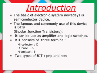
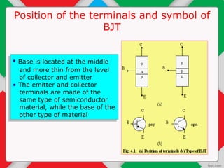
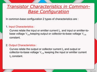
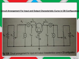


The document details the input and output characteristics of bipolar junction transistors (BJTs), covering their basic configuration, terminal positions, and the distinction between PNP and NPN types. It explains the input and output characteristics in common-base configuration, highlighting the regions: active, cutoff, and saturation, as well as concepts like knee voltage and dynamic resistances. Overall, it serves as a foundational overview of BJTs used as amplifiers and switches in electronic systems.