
Recommended
More Related Content
What's hot
What's hot (20)
Similar to Governors ppt.pdf .
Similar to Governors ppt.pdf . (20)
More from happycocoman
More from happycocoman (20)
Recently uploaded
Recently uploaded (20)
Governors ppt.pdf .
- 1. Governors
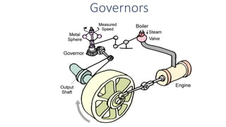
- 2. Governors • A governor is a device to maintain, as closely as possible, a constant mean speed of rotation of the crankshaft over long periods during which the load on the engine may vary. The governor meets the varying demand for power by regulating the supply of working fluid. • Types Of Governors There are basically two types of governors. 1. Centrifugal governors 2. Inertia governor.
- 3. Classification The governors may be broadly classified as: Centrifugal governor Inertia governor Loaded Type Pendulum Type Watt governor Dead Weight Type Spring Controlled • Porter governor • Proell governor • Hartnell governor • Hartung governor • Wilson-Hartnell governor • Pickering governor
- 4. • The centrifugal governors are based on the principle of balancing of centrifugal force on the rotating balls (mass) by an equal and opposite radial force, known as the controlling force.
- 5. • Governor balls or fly balls revolve with a spindle, which is driven by the engine through bevel gears. • The upper ends of the arms are pivoted to the spindle, so that the balls may rise up or fall down as they revolve about the Spring steel vertical axis.
- 6. The sleeve revolves with the spindle but can slide up and down. The balls and the sleeve rises when the spindle speed increases, and falls when the speed decreases. The sleeve is connected by a bell crank lever to a throttle valve.
- 7. • The supply of the working fluid decreases when the sleeve rises and increases when it falls. When the load on the engine increases, the engine and the governor speed decreases. • This results in the decrease of centrifugal force on the flyballs. Hence weight of the flyballs move inwards and the sleeve moves down- wards.
- 8. • The downward movement of the sleeve operates a throttle to increase the supply of working fluid and thus the engine speed is increased.
- 9. Terminology 3. Radius of rotation : The horizontal distance from the axis of rotation to the center of the ball mass at any speed. 4. Maximum equilibrium speed: The speed at maximum radius of rotation is called the maximum equilibrium speed 5. Minimum equilibrium speed: The speed at minimum radius of rotation is called the minimum equilibrium speed 6. Sleeve Lift : It is the vertical distance which the sleeve travels due to change in equilibrium speed. 1. Height of a governor. It is the vertical distance from the center of the ball to a point where the axes of the arms (or arms produced) intersect on the spindle axis. It is usually denoted by h. 2. Equilibrium speed. It is the speed at which the governor balls, arms etc., are in complete equilibrium and the sleeve does not tend to move upwards or downwards.
- 10. • A governor is said to be sensitive when it readily responds to a small change of speed. The movement of the sleeve for a fractional change of speed is the measure of sensitivity. • As a governor is used to limit the change of speed of the engine between minimum to full-load conditions, the sensitiveness of a governor is also defined as the ratio of the difference between the maximum and the minimum speeds (range of speed) to the mean equilibrium speed. • Thus, 𝑆𝑒𝑛𝑠𝑖𝑡𝑖𝑣𝑒𝑛𝑒𝑠𝑠 = 𝑅𝑎𝑛𝑔𝑒 𝑜𝑓 𝑠𝑝𝑒𝑒𝑑 𝑀𝑒𝑎𝑛 𝑠𝑝𝑒𝑒𝑑 = 𝑁2 − 𝑁1 𝑁 = 2 𝑁2 − 𝑁1 𝑁2 + 𝑁1 (i.e. considering a governor fitted to engine)
- 11. •Problem faced by an over-sensitive governor, leading to continuous fluctuation, because when the load on the engine changes, the sleeve rapidly fluctuates between the extreme positions. • When the load on the engine falls, the sleeve rises rapidly to a maximum position. This shuts off the fuel supply to the extent to affect a sudden fall in the speed. As the speed falls to below the mean value, the sleeve again moves rapidly and falls to a minimum position to increase the fuel supply. The speed subsequently rises and becomes more than the average with the result that the sleeve again rises to reduce the fuel supply. This process repeats and is known as hunting
- 12. ISOCHRONISM • A governor with a zero range of speed is known as an isochronous governor. (Note:- This definition is as per sensitivity expression of governor considered individually or isolated) • This means that for all positions of the sleeve or the balls, the governor has the same equilibrium speed. • An isochronous governor is not practical due to friction at the sleeve.
- 13. STABILITY •A governor is said to be stable if it brings the speed of the engine to the required value and there is not much hunting. •The ball masses occupy a definite position for each speed of the engine within the working range.
- 14. WATT GOVERNOR Types of Watt Governor
- 15. WATT GOVERNOR Let m = mass of each ball W = weight of each ball (mg) ω = angular velocity of balls arms and sleeve T =Tension in the arm r = radial distance of ball- centre from spindle axis Assuming – (i) The links to be massless and (ii) Neglecting the friction of the sleeve, the mass m at A is in static equilibrium under the action of Weight w (=mg) Centrifugal force mrω2 Tension T in the upper link Note: If sleeve is massless and friction is neglected, the lower links will be tension free.
- 16. Taking moment about ‘O’,
- 17. In this type of governor, the movement of the sleeve is very less at high speeds and thus, is unsuitable for high speeds. However, this drawback has been overcome by loading the governor with a dead weight or by means of a spring. From the derived expression, on substitution of the various speed values the following chart data is obtained -
- 18. 1. Considering Fig (b) for a Watt Governor where AE =400 mm , EF = 50 mm and angle =350 . Determine percentage change in speed when angle = 300 h = GO = GH + HO = AE cos + EH cot h1 = 400 cos 35 + 25 cot 35 = 363.4 mm ; N1 = 49.63 rpm h2 = 400 cos 30 + 25 cot 30 = 389.7 mm ; N2 = 47.92 rpm Therefore Percentage change in speed = 3.44 O H G 2. Calculate the vertical height of a watt governor when it rotates at 60 rpm . Also find the change in vertical height when its speed increases to 61 rpm. h1 = 895 602 = 0.248 m ; h2 = 895 612 = 0.240 m Change in vertical height = h1 - h2 =0.248 – 0.240 = 0.008 m 8mm
- 19. Porter governor If the sleeve of a Watt governor is loaded with a heavy mass, it becomes a Porter governor Let M= mass of the sleeve m = mass of each ball f = force of friction at the sleeve h = height of the governor r = distance of the center of each ball from axis of rotation The instantaneous center of rotation of the link AB is at I for the given configuration of the governor. It is because the motion of its two points A and B relative to the link is known. The point A oscillates about the point O and B moves in a vertical direction parallel to the axis. Lines perpendicular to the direction of these motions locates the point I.
- 20. The force of friction always acts in a direction opposite to that of the motion. Thus when the sleeve moves up, the force of friction acts in the downward direction and the downward force acting on the sleeve is (Mg + f). Similarly, when the sleeve moves down, the force on the sleeve will be (Mg - f ). In general, the net force acting on the sleeve is (Mg ± f) depending upon whether the sleeve moves upwards or downwards. Considering the symmetry of governor about the spindle axis governor and taking moments about I,
- 22. Different situations, This equation would provide two values of N for the same height h of the governor. For a particular height, Speed in increasing mode – Sleeve lifted up – (𝑀𝑔+f) – Higher limit of speed on substitution in formula –(say 600rpm) unless exceeded no change in height. Speed in decreasing mode – Sleeve goes down– (𝑀𝑔-f) – Lower limit of speed on substitution in formula –(say 200rpm) unless reduces more no change in height. Conclusion – Within the speed limit of 600-200 rpm – no height change ( insensitive @ this speed range).
- 23. Proell governor A porter governor is known as a Proell governor if the two fly balls (masses) are fixed on the upward extensions of the lower links which are in the form of bent links BAE and CDF.
- 24. Considering the equilibrium of the link BAE which is under the action of :- Weight of the ball, mg Centrifugal force, mr’ω2 Tension in the link AO, T Weight of sleeve and friction, 𝟏 𝟐 (𝐌𝐠 ± 𝐟) Taking moment about I the instantaneous centre of link BAE 𝐦𝐫′ 𝛚𝟐 𝐞 = 𝐦𝐠 (𝐜 + 𝐫 − 𝐫′ ) + 𝐌𝐠 ± 𝐟 𝟐 (𝐜 + 𝐛) Where b, c, a and r are the dimensions as indicated in the diagram. 𝐦𝐫′𝛚𝟐 = 𝟏 𝐞 [𝐦𝐠 𝐜 + 𝐫 − 𝐫′ + 𝐌𝐠±𝐟 𝟐 𝐜 + 𝐛 ] (dividing equation by e) Considering the situation where AE is vertical, i.e. neglecting its obliquity, 𝐦𝐫𝛚𝟐 = 𝟏 𝐞 [𝐦𝐠𝐜 + 𝐌𝐠 ± 𝐟 𝟐 𝐜 + 𝐛 ] = 𝐚 𝐞 [𝐦𝐠 𝐜 𝐚 + 𝐌𝐠 ± 𝐟 𝟐 𝐜 𝐚 + 𝐛 𝐚 ] (multipling and dividing equation by a)
- 25. = 𝒂 𝒆 [𝒎𝒈 𝒄 𝒂 + 𝑴𝒈 ± 𝒇 𝟐 𝒄 𝒂 + 𝒃 𝒂 ] = 𝒂 𝒆 [𝒎𝒈 𝒕𝒂𝒏 𝜽 + 𝑴𝒈 ± 𝒇 𝟐 𝒕𝒂𝒏 𝜽 + 𝒕𝒂𝒏 𝜷 ] Taking ‘tanθ’ common and 𝒕𝒂𝒏 𝜷 𝒕𝒂𝒏 𝜽 = 𝒌 = 𝒂 𝒆 𝒕𝒂𝒏 𝜽 [𝒎𝒈 + 𝑴𝒈 ± 𝒇 𝟐 𝟏 + 𝒌 ] 𝒎𝒓𝝎𝟐 = 𝒂 𝒆 𝒓 𝒉 [𝒎𝒈 + 𝑴𝒈 ± 𝒇 𝟐 𝟏 + 𝒌 ] Dividing and multiplying by ‘g’ 𝟐𝝅𝑵 𝟔𝟎 𝟐 = 𝒂 𝒆 𝒈 𝒉 𝟐𝒎𝒈 + 𝑴𝒈 ± 𝒇 𝟏 + 𝒌 𝟐𝒎𝒈 (Taking g= 9.81 m/s2) 𝑵𝟐 = 𝟖𝟗𝟓 𝒉 𝒂 𝒆 𝟐𝒎𝒈 + 𝑴𝒈 ± 𝒇 𝟏 + 𝒌 𝟐𝒎𝒈
- 26. 𝑵𝟐 = 𝟖𝟗𝟓 𝒉 𝒂 𝒆 𝟐𝒎𝒈 + 𝑴𝒈 ± 𝒇 𝟏 + 𝒌 𝟐𝒎𝒈 On observation of the above formula, for a given value of m, M, and h the speed is reduced compared to the porter governor. In order to maintain the same equilibrium speed smaller masses (m) can be used. Different conditions, 𝐈𝐟 𝐤 = 𝟏, 𝑵𝟐 = 𝟖𝟗𝟓 𝒉 𝒂 𝒆 𝒎𝒈 + 𝑴𝒈 ± 𝒇 𝒎𝒈 𝐈𝐟 𝐟 = 𝟎, 𝑵𝟐 = 𝟖𝟗𝟓 𝒉 𝒂 𝒆 𝟐𝒎 + 𝑴 𝟏 + 𝒌 𝟐𝒎 𝐈𝐟 𝐤 = 𝟏, 𝐟 = 𝟎 𝑵𝟐 = 𝟖𝟗𝟓 𝒉 𝒂 𝒆 𝒎 + 𝑴 𝒎
- 27. Hartnell governor In this type of governor, the balls are controlled by a spring as shown in figure. Initially, the spring is fitted in compression so that a force is applied to the sleeve. Two bell -crank levers, each carrying a mass at one end and a roller at the other, are pivoted to a pair of arms which rotate with the spindle. The rollers fit into a groove in the sleeve.
- 28. PROTOTYPE OF A HARTNELL GOVERNOR available in MECH LAB Spring load Flyball masses Sleeve Bell crank lever
- 29. Assuming that the sleeve moves up so that f is taken positive. Let F = centrifugal force = m𝑟𝜔2 Fs= spring force M= mass of sleeve Taking moments about the fulcrum A, F1a1= 1 2 𝑀𝑔 + 𝐹𝑠1 + 𝑓 𝑏1 + 𝑚𝑔𝑐1 F2a2= 1 2 𝑀𝑔 + 𝐹𝑠2 + 𝑓 𝑏2 − 𝑚𝑔𝑐2 In the working range of the governor, ‘θ’ is usually small and so the obliquity effects of the arms of the bell crank levers may be neglected. In that case, a1=a2=a, b1=b2=b, c1=c2=0
- 30. F1a = 1 2 𝑀𝑔 + 𝐹𝑠1 + 𝑓 𝑏_________(i) F2a = 1 2 𝑀𝑔 + 𝐹𝑠2 + 𝑓 𝑏 _________(𝑖𝑖) On rearranging, (F2-F1)a = 1 2 𝐹𝑠2 − 𝐹𝑠1 𝑏 (FS2-FS1) = 2𝑎 𝑏 𝐹2 − 𝐹1 Let s = stiffness of the spring and h1 = movement of the sleeve (FS2-FS1) = h1s = 2𝑎 𝑏 𝐹2 − 𝐹1 Subtracting (i) from (ii) 𝑠 = 2 ℎ1 . 𝑎 𝑏 . 𝐹2 − 𝐹1 𝑠 = 2 𝑟2 − 𝑟1 . 𝑎 𝑏 2 . 𝐹2 − 𝐹1 𝑠 = 2. 𝑎 𝑏 2 . 𝐹2 − 𝐹1 𝑟2 − 𝑟1 But ℎ1 = 𝜃. 𝑏 = 𝑟2−𝑟1 𝑎 . 𝑏
- 31. 31 mm In a Hartnell governor, the extreme radii of rotation of the balls are 40 mm and 60 mm, and the corresponding speeds are 210 rpm and 230 rpm. The mass of each ball is 3 kg. The lengths of the ball and the sleeve arms are equal. Determine the initial compression and the constant of the central spring
- 32. In a spring -loaded governor of the Hartnell type. The lengths of the horizontal and the vertical arms of the bell -crank lever are 40 mm and 80 mm respectively. The mass of each ball is 1.2 kg. The extreme radii of rotation of the balls are 70 mm and 105 mm. The distance of the fulcrum of each bell-crank lever is 75 mm from the axis of rotation of the governor. The minimum equilibrium speed is 420 rpm and the maximum equilibrium speed is 4% higher than this. Neglecting the obliquity of the arms, determine the (i) spring stiffness, (ii) initial compression, and (iii) equilibrium speed corresponding to radius of rotation of 95 mm.
- 34. • The effort of the governor is the mean force acting on the sleeve to raise or lower it for a given change of speed. • At constant speed, the governor is in equilibrium and the resultant force acting on the sleeve is zero. However, when the speed of the governor increases or decreases, a force is exerted on the sleeve which tends to move it. When the sleeve occupies a new steady position, the resultant force acting on it again becomes zero. If the force acting at the sleeve changes gradually from zero (when the governor is in the equilibrium position) to a value E for an increased speed of the governor, the mean force or the effort is E/2.
- 35. ℎ = 𝑔 𝜔2 + 𝑀𝑔(1 + 𝑘) 2𝑚𝜔2 = 2𝑚𝑔 + 𝑀𝑔 1 + 𝑘 2𝑚𝜔2 (𝑖) ℎ = 2𝑚𝑔 + 𝑀𝑔 + 𝐸 1 + 𝑘 2𝑚 1 + 𝑐 2𝜔2 (𝑖𝑖) 2𝑚𝑔 + 𝑀𝑔 + 𝐸 1 + 𝑘 2𝑚𝑔 + 𝑀𝑔 1 + 𝑘 = 1 + 𝑐 2 1 2𝑚𝑔 + 𝑀𝑔 + 𝐸 1 + 𝑘 2𝑚𝑔 + 𝑀𝑔 1 + 𝑘 − 1 = 1 + 𝑐 2 1 − 1 2𝑚𝑔 + 𝑀𝑔 + 𝐸 1 + 𝑘 − 2𝑚𝑔 + 𝑀𝑔 1 + 𝑘 2𝑚𝑔 + 𝑀𝑔 1 + 𝑘 = 1 + 2𝑐 + 𝑐2 − 1 1 𝐸 1 + 𝑘 2𝑚𝑔 + 𝑀𝑔 1 + 𝑘 = 2𝑐 For a porter governor, Dividing (ii) by (i), 𝑐2 being small quantity, is neglected leaving, Suppose speed increases by amount ‘c’, to keep the sleeve at the same position, i.e. to maintain the height @ ‘h’ constant extra force of ‘E’ is applied on the sleeve.
- 36. 𝐸 1 + 𝑘 2𝑚𝑔 + 𝑀𝑔 1 + 𝑘 = 2𝑐 𝐸 = 2𝑐 1 + 𝑘 2𝑚𝑔 + 𝑀𝑔 1 + 𝑘 𝐸 2 = 𝑐𝑔 1 + 𝑘 2𝑚 + 𝑀 1 + 𝑘 𝐼𝑓 𝑘 = 1 𝐸 2 = 𝑚 + 𝑀 𝑐𝑔 𝐼𝑓 𝑘 = 1 𝑎𝑛𝑑 𝑓𝑟𝑖𝑐𝑡𝑖𝑜𝑛 𝑜𝑓 𝑠𝑙𝑒𝑒𝑣𝑒 𝑐𝑜𝑛𝑠𝑖𝑑𝑒𝑟𝑒𝑑 𝐸 2 = 𝑚𝑔 + 𝑀𝑔 + 𝑓 𝑐 𝐹𝑜𝑟 𝑤𝑎𝑡𝑡 𝑔𝑜𝑣𝑒𝑟𝑛𝑜𝑟 𝑀 = 0 𝐸 2 = 𝑚𝑐𝑔 𝐸𝑓𝑓𝑜𝑟𝑡, 𝑬𝒇𝒇𝒐𝒓𝒕 𝒂𝒍𝒔𝒐 𝒄𝒂𝒏 𝒃𝒆 𝒅𝒆𝒇𝒊𝒏𝒆𝒅 as force required to change 1% in speed = 𝟎. 𝟎𝟏 𝒎 + 𝑴 𝒈
- 37. The power of a governor is the work done at the sleeve for a given percentage change of speed, i.e., it is the product of the effort and the displacement of the sleeve.
- 39. N2 N2