SlideShare a Scribd company logo
1 of 33
Download to read offline
GOVERNORS AND FLYWHEEL
Governor:-
To minimize fluctuations in the mean speed which may occur due to load variation,
governor is used.
The function of governor is to increase the supply of working fluid going to the
prime-mover when the load on the prime-mover increases and to decrease the
supply when the load decreases so as to keep the speed of the prime-mover almost
constant at different loads.
Example: when the load on an engine increases, its speed decreases, therefore it
becomes necessary to increase the supply of working fluid. On the other hand,
when the load on the engine decreases, its speed increases and hence less working
fluid is required.
Classification of Centrifugal Governors:
Centrifugal Governor:
In these governors, the change in centrifugal forces of the rotating masses due to
change in the speed of the engine is utilized for movement of the governor sleeve.
These governors are commonly used because of simplicity in operation.
It consists of two balls of equal mass, which are attached to the arms. These
balls are known as governor balls or fly balls.
The balls revolve with a spindle, which is driven by the engine through bevel gears.
The upper ends of the arms are pivoted to the spindle, so that the balls may
rise up or fall down as they revolve about the vertical axis.
The sleeve revolves with the spindle; but can slide up and down. The balls and
the sleeve rise when the spindle speed increases, and falls when the speed
decreases.
In order to limit the travel of the sleeve in upward and downward directions,
two stops S, S are provided on the spindle.
The sleeve is connected by a bell crank lever to a throttle valve. The supply of
the working fluid decreases when the sleeve rises and increases when it falls.
When the load on the engine increases, the engine and the governor speed
decreases. This results in the decrease of centrifugal force on the balls. Hence
the balls move inwards and the sleeve moves downwards. The downward
movement of the sleeve operates a throttle valve at the other end of the bell
crank lever to increase the supply of working fluid an Thus the engine speed
is increased. Hence, the extra power output is provided to balance the
increased load.
When the load on the engine decreases, the engine and the governor speed
increases, which results in the increase of centrifugal force on the balls. Thus
the balls move outwards and the sleeve rises upwards. This upward movement
of the sleeve reduces the supply of the working fluid and hence the speed is
decreased. Hence, the power output is reduced.
Types of Centrifugal Governors: Depending on the construction these
governors are of two types:
(a)Gravity controlled centrifugal governors,
(b)Spring controlled centrifugal governors.
(a)Gravity Controlled Centrifugal Governors-In this type of governors there is
gravity force due to weight on the sleeve or weight of sleeve itself which
controls movement of the sleeve. These governors are comparatively larger in
size.
Spring Controlled Centrifugal Governors-In these governors, a helical spring
or several springs are utilized to control the movement of sleeve or balls.
These governors are comparatively smaller in size.
There are three commonly used gravity controlled centrifugal governors
(a) Watt governor
(b)Porter governor
(c) Proell governor
Watt governor does not carry dead weight at the sleeve. Porter governor and
Proell governor have heavy dead weight at the sleeve. In porter governor balls
are placed at the junction of upper and lower arms. In case of Proell governor
the balls are placed at the extension of lower arms. The sensitiveness of watt
governor is poor at high speed and this limits its field of application. Porter
governor is more sensitive than watt governor. The Proell governor is most
sensitive out of these three.
Watt Governor:
This governor was used by James Watt in his steam engine. The spindle is
driven by the output shaft of the prime mover. The balls are mounted at the
junction of the two arms. The upper arms are connected to the spindle and
lower arms are connected to the sleeve.
We ignore mass of the sleeve, upper and lower arms for simplicity of analysis.
We can ignore the friction also. The ball is subjected to the three forces which
are centrifugal force (Fc), weight (mg) and tension by upper arm (T). Taking
moment
We ignore mass of the sleeve, upper and lower arms for simplicity of analysis.
We can ignore the friction also. The ball is subjected to the three forces which
are centrifugal force (Fc), weight (mg) and tension by upper arm (T). Taking
moment about point O(intersection of arm and spindle axis), we get
Porter Governor:
A schematic diagram of the porter governor is shown in Figure 5.4(a).
There are two sets of arms. The top arms OA and OB connect balls to the
hinge O. The hinge may be on the spindle or slightly away. The lower arms
support dead weight and connect balls also. All of them rotate with the spindle.
We can consider one-half of governor for equilibrium.
Let ii be the w'eiR3 t Of the ball.Ti and T,
• be tension in upper and lower arms. respectively.
N, be the centrifugal force.
r be the radius of rotation of the ball from axis. and
I is the instantaneous center of the louder arm.
Taking moment of all for Yes acting on the ball about I and neglecting friction at the
sleex‘e. u°e get
DC x AD — ›s x ID ——/C=0
or
or
or (1+K)
If friction at the sleeve is f, the force at the sleeve should be replaced by W+ for
rising and by (W–f) for falling speed as friction opposes the motion of sleeve.
Therefore, if the friction at the sleeve is to be considered, should be replaced by
(W
Spring controlled centrifugal governor: In these governors springs are used to
counteract the centrifugal force. They can be designed to operate at high speeds.
They are comparatively smaller in size. Their speed range can be changed by
changing the initial setting of the spring. They can work with inclined axis of
rotation also. These governors may be very suitable for IC engines, etc.
The most commonly used spring controlled centrifugal governors are :
a) Hartwell governor
b)Wilson-Hartwell governor
(b)Hartung governor
Hartnell Governor: The Hartnell governor is shown in Figure 5.5. The two
bell crank levers have been provided which can have rotating motion about
fulcrums Oand O . One end of each bell crank lever carries a ball and a roller
at the end of other arm. The rollers make contact with the sleeve. The frame is
connected to the spindle. A helical spring is mounted around the spindle
between frame and sleeve. With the rotation of the spindle, all these parts
rotate. With the increase of speed, the radius of rotation of the balls increases
and the rollers lift the sleeve against the spring force. With the decrease in
speed, the sleeve moves downwards. The movement of the sleeve is
transferred to the throttle of the engine through linkage.
Characteristics of Governors:
Different governors can be compared on the basis of following characteristics.
 Stability: A governor is said to be stable when for every speed within
the working range there is a definite configuration i.e. there is only one
radius of rotation of the governor balls at which the governor is in
equilibrium. For a stable governor, if the equilibrium speed increases,
the radius of governor balls must also increase.
 Sensitiveness of Governors: If a governor operates between the speed
limits N1 and N2, then sensitiveness is defined as the ratio of the mean
speed to the difference between the maximum and minimum speeds.
Thus,N1 = Minimum equilibrium speed, N2 = Maximum equilibrium
speed, and
 Isochronous Governors:
A governor is said to be isochronous when the
equilibrium speed is constant (i.e. range of speed is zero) for all radii of rotation of
the balls within the working range, neglecting friction. The isochronisms are the
stage of infinite sensitivity. The isochronous governor is not of practical use because
the sleeve will move to one of its extreme positions immediately the speed deviates
from the isochronous speed.
 Hunting : Hunting is the name given to a condition in which the speed of the
engine controlled by the governor fluctuates continuously above and
below the mean speed. It is caused by a governor which is too sensitive
and which, therefore, changes by large amount the supply of fuel to the
engine.
Flywheel:
A flywheel used in machines serves as a reservoir which stores energy during the
period when the supply of energy is more than the requirement and releases it
during the period when the requirement of energy is more than supply.
For example, in I.C. engines, the energy is developed only during power stroke
which is much more than the engine load, and no energy is being developed during
suction, compression and exhaust strokes in case of four stroke engines and during
compression in case of two stroke engines. The excess energy developed during
power stroke is absorbed by the flywheel and releases it to the crankshaft during
other strokes in which no energy is developed, thus Flywheel rotating the crankshaft
at a uniform speed. when the flywheel absorbs energy, its speed increases and when
it releases, the speed decreases. Hence a flywheel does not maintain a constant
speed; it simply reduces the fluctuation of speed.
In other words, a flywheel controls the speed variations caused by the fluctuation of
the engine turning moment during each cycle of operation. It does not control the
speed variations caused by the varying load.
Coefficient of fluctuation of speed:
Maximum Fluctuation of Energy: A turning moment diagram for a multi-
cylinder engine is shown by a wavy curve in Fig. 22.4.
The horizontal line AG represents the mean torque line. Let a1, a3, a5 be the
areas above the mean torque line and a2, a4 and a6 be the areas below the
mean torque line. These areas represent some quantity of energy which is
either added or subtracted from the energy of the moving parts of the engine.
Coefficient of fluctuation of energy:
Difference between Flywheel and Governor
Power Transmission
Power transmission devices are very commonly used to transmit power from one
shaft to another. Belts, chains and gears are used for this purpose. When the
distance between the shafts is large, belts or ropes are used and for intermediate
distance chains can be used. For belt drive distance can be maximum but this should
not be more than ten metres for good results. Gear drive is used for short distances.
1. Belts and ropes are used when the distance between the axes of the two shafts to
be connected is considerable. Such connectors are non-rigid and undergo strain
while in motion. These devices are called non-positive drive because of the
possibility of slip occurring between the belt and pulley.
2. Chain drive is used when the distance between the shaft centers is short and no
slip is required. These connectors are referred to as a positive or non-slip drive.
3. Gears are used for transmitting motion and power when the distance between
the driving& driven shafts is relatively small, and when a constant velocity ratio
is desired.
4. Clutches are used for power transmission between co-axial shafts.
Belts
In case of belts, friction between the belt and pulley is used to transmit power. In
practice, there is always some amount of slip between belt and pulleys, therefore,
exact velocity ratio cannot be obtained. That is why, belt drive is not a positive
drive. Therefore, the belt drive is used where exact velocity ratio is not required.
The following types of belts shown in Figure 3.1 are most commonly used :
The flat belt is rectangular in cross-section as shown in Figure 3.1(a). The
pulley for this belt is slightly crowned to prevent slip of the belt to one side. It
utilises the friction between the flat surface of the belt and pulley.
The V-belt is trapezoidal in section as shown in Figure 3.1(b). It utilizes the force
of friction between the inclined sides of the belt and pulley. They are preferred
when distance is comparative shorter. Several V-belts can also be used together if
power transmitted is more.
The circular belt or rope is circular in section as shown in Figure 8.1(c).
Several ropes also can be used together to transmit more power.
The belt drives are of the following types :
(a) open belt drive, and
(b) cross belt drive.
Open Belt Drive
Open belt drive is used when sense of rotation of both the pulleys is same. It is
desirable to keep the tight side of the belt on the lower side and slack side at the top
to increase the angle of contact on the pulleys. This type of drive is shown in
Figure 3.2.
Cross Belt Drive
In case of cross belt drive, the pulleys rotate in the opposite direction. The
angle of contact of belt on both the pulleys is equal. This drive is shown in
Figure 3.3. As shown in the figure, the belt has to bend in two different
planes. As a result of this, belt wears very fast and therefore, this type of drive
is not preferred for power transmission. This can be used for transmission of
speed at low power.
(i) Crossed belt system: the crossed belt system in which the driving and the
drivenpulleys rotate in opposite directions.
The belt leaves the bigger pulley at A and C and the smaller pulley at Band D. A line
02M is drawn parallel at AB will be perpendicular to O1A also.
Through binomial expansion
It may be noted from equations 1and 2 that:
(I) The length of a crossed belt is more than that of an open belt, other conditions
remainingthe same.
(ii) The total length of a crossed belt is a function of (r1 + r2). If the sum of
the radii of two pulleys be constant, the length of the cross belt required will
be also remain constant.
Ratio of tension
Figure shows a flexible belt resting over the flat rim of a stationary pulley. The
tensions T1and are such that the motion is impending Oust to take place) between
the belt and the pulley. Considering the impending motion to be clockwise relative
to the drum, the tension T1 is more than T2 is to be noted that only a part of the belt
is in contact with the pulley. The angle subtended at the centre of the pulley by the
position of belt in contact with it is called the angle of contact or the angle of lap
Angle of contact θ = angle .AGB
Let attention be focused on small element EF of the belt which subtends an angle
δθ at the centre. The segment EF is acted upon by the following set of forces:
• Tension T in the belt acting tangentially at S,
• Tension ( T + 8T) in the belt acting tangentially at R
• Normal reaction R exerted by the pulley rim, and
• Friction force F = μR which acts against the tendency to slip and is
perpendicular to normal reaction R.
Power Transmitted by Belt Drive
The power transmitted by the belt depends on the tension on the
two sides and the belt speed. Let T1 be the tension on the tight
side in ‗N‘
T2 be the tension on the slack side in ‗N‘, and
V be the speed of the belt in m/sec.
Then power transmitted by the belt is given by
Tension due to Centrifugal Forces
The belt has mass and as it rotates along with the pulley it is subjected to
centrifugal forces. If we assume that no power is being transmitted and pulleys
are rotating, the centrifugal force will tend to pull the belt as shown in Figure
3.14(b) and, thereby, a tension in the belt called centrifugal tension will be
introduced.
Let ‗TC‘ be the centrifugal tension due to centrifugal force.
Let us consider a small element which subtends an angle at the centre of the pulley.
Let ‗m‘ be the mass of the belt per unit length of the belt in ‗kg/m‘.
Initial Tension
When a belt is mounted on the pulley some amount of initial tension say ‗T0‘ is
provided in the belt, otherwise power transmission is not possible because a loose
belt cannot sustain difference in the tension and no power can be transmitted. When
the drive is stationary the total tension on both sides will be ‗2 T0‘.
When belt drive is transmitting power the total tension on both sides will be (T1 +
T2), where T1 is tension on tight side, and T2 is tension on the slack side.
If effect of centrifugal tension is neglected.
Maximum Power Transmitted
The power transmitted depends on the tension ‗T1‘, angle of lap , coefficient
of friction ‗ ‘ and belt speed ‗V‘. For a given belt drive, the maximum tension
(Tt), angle of lap and coefficient of friction shall remain constant provided that
(a) the tension on tight side, i.e. maximum tension should be equal to the maximum
permissible value for the belt, and
(b) the belt should be on the point of slipping.
Maximum Power Transmitted
The power transmitted depends on the tension ‗T1‘, angle of lap , coefficient
of friction ‗ ‘ and belt speed ‗V‘. For a given belt drive, the maximum tension
(Tt), angle of lap and coefficient of friction shall remain constant provided that
(c) the tension on tight side, i.e. maximum tension should be equal to the maximum
permissible value for the belt, and
(d) the belt should be on the point of slipping.
Gear Drive
A gear is a wheel provided with teeth which mesh with the teeth on another wheel,
or on to a rack, so as to give a positive transmission of motion from one component
to another.
They are commonly used for power transmission or for changing power speed
ratio in a power system but when they are not too far apart and when a constant
velocity ratio is desired.
Advantages and Disadvantages of Gear Drive
The following are the advantages and disadvantages of the gear drive as compared
to belt, rope and chain drives:
Advantages
1. It transmits exact velocity ratio.
2. It may be used to transmit large power.
3. It has high efficiency.
4. It has reliable service.
5. It has compact layout.
Disadvantages
1. The manufacture of gears require special tools and equipment.
2. The error in cutting teeth may cause vibrations and noise during operation
Definitions
There are several notation which are given below:
1.Pitch circle. It is an imaginary circle which by pure rolling action, would
give thesame motion as the actual gear.
2.Pitch circle diameter. It is the diameter of the pitch circle. The size of the
gear is usually specified by the pitch circle diameter. It is also known as
pitch diameter.
3.Pitch point. It is a common point of contact between two pitch circles.
4.Pitch surface. It is the surface of the rolling discs which the meshing gears
have replaced at the pitch circle.
5.Pressure angle or angle of obliquity. It is the angle between the common
normal to two gear teeth at the point of contact and the common tangent at
the pitch point. It is usually denoted by φ. The standard pressure angles are
14½ ° and 20°
6.Addendum. It is the radial distance of a tooth from the pitch circle to the top
of the tooth.
7.Dedendum. It is the radial distance of a tooth from the pitch circle to the
bottom of the tooth.
8.Addendum circle. It is the circle drawn through the top of the teeth and is
concentric with the pitch circle.
9.Dedendum circle. It is the circle drawn through the bottom of the teeth. It is
also calledroot circle.
Note: Root circle diameter = Pitch circle diameter × cos φ, where φ is the pressure angle
10. Circular pitch. It is the distance measured on the circumference of the pitch circle
froma point of one tooth to the corresponding point on the next tooth. It is usually
denoted by pc. Mathematically,
Circular pitch, Pc = Π D/T
where D = Diameter of the pitch
circle, and T = Number of teeth on the
wheel.
A little consideration will show that the two gears will mesh together correctly,
if the two wheels have the same circular pitch.
Note: If D1 and D2 are the diameters of the two meshing gears having the
teeth T1 and T2 respectively, then for them to mesh correctly,
PC = Π D1/T =Π D2/T
11. Diametral pitch. It is the ratio of number of teeth to the pitch circle diameter in
millimetres. It is denoted by pd . Mathematically,
Diametral pitch, Pd
=T/D=Π/ PC where T =
Number of teeth, and D =
Pitch circle diameter.
12. Module. It is the ratio of the pitch circle diameter in millimeters to the number
of teeth. Itis usually denoted by m. mathematically,
Module, m = D /T
Note : The recommended series of modules in Indian Standard are 1, 1.25, 1.5, 2, 2.5, 3,
4, 5,
6, 8, 10, 12, 16, and 20. The modules 1.125, 1.375, 1.75, 2.25, 2.75, 3.5, 4.5, 5.5, 7, 9, 11,
14
and 18 are of second choice.
13. Clearance. It is the radial distance from the top of the tooth to the bottom of the
tooth, ina meshing gear. A circle passing through the top of the meshing gear is known
as clearance circle.
14. total depth. It is the radial distance between the addendum and the dedendum
circles ofa gear. It is equal to the sum of the addendum and dedendum.
15.Working depth. It is the radial distance from the addendum circle to the
clearance circle.It is equal to the sum of the addendum of the two meshing gears.
16.Tooth thickness. It is the width of the tooth measured along the pitch circle.
17. Tooth space . It is the width of space between the two adjacent teeth
measured alongthe pitch circle.
18.Backlash. It is the difference between the tooth space and the tooth
thickness, as measured along the pitch circle. Theoretically, the backlash should
be zero, but in actual practice some backlash must be allowed to prevent
jamming of the teeth due to tooth errors and thermal expansion.
19.Face of tooth. It is the surface of the gear tooth above the pitch surface.
20.Flank of tooth. It is the surface of the gear tooth below the pitch surface.
21.Top land. It is the surface of the top of the tooth.
22.Face width. It is the width of the gear tooth measured parallel to its axis.
23.Profile. It is the curve formed by the face and flank of the tooth.
24.Fillet radius. It is the radius that connects the root circle to the profile of the tooth.
25.Path of contact. It is the path traced by the point of contact of two teeth from the
beginning to the end of engagement.
26.Length of the path of contact. It is the length of the common normal cut-off by the
addendum circles of the wheel and pinion.
27.Arc of contact. It is the path traced by a point on the pitch circle from the beginning
to the end of engagement of a given pair of teeth. The arc of contact consists of two
parts, i.e.
(a) Arc of approach. It is the portion of the path of contact from the
beginning of the engagement to the pitch point.
(b) Arc of recess. It is the portion of the path of contact from the pitch point to
the end of the engagement of a pair of teeth.
Note : The ratio of the length of arc of contact to the circular pitch is known as contact
ratio
i.e. number of pairs of teeth in contact.
Types of gear
There are mainly five types of gear
1. Spur gear
2. Helical gear
3. Bevel gear
4. Worm gear
5. Rack & pinion gear
Spur gear
Spur gears or straight-cut gears are the simplest type of gear. They consist ofa
cylinder or disk, and with the teeth projecting radially, and although they are not
straight-sided in form, the edge of each tooth thus is straight and aligned parallel to
the axis of rotation. These gears can be meshed together correctly only if they are
fitted to parallel axles. The arrangement is known as spur gearing.
Helical gear
The teeth of helical gear are inclined to the axis In this type of gear. This ensures
smooth action & more accurate maintenance of velocity ratio.
The disadvantage is that the inclination of the teeth sets up a lateral thrust. A method
of neutralizing this lateral or axial thrust is to use double helical gears (also known as
herring bone gear)
(a)Single helical gear (b) double helical gear
Bevel gear
The two non-parallel or intersecting, but coplanar shafts connected by gears are
called bevel gears and the arrangement is known as bevel gearing. The bevel
gears, like spur gears, may also have their teeth inclined to the face of the bevel, in
which case they are known as helical bevel gears. The two non-intersecting and
non-parallel i.e. non-coplanar shaft connected by gears are called skew bevel gears
or spiral gears and the arrangement is known as skew bevel gearing or spiral
gearing. This type of gearing also has a line contact, the rotation of which about the
axes generates the two pitch surfaces known as hyperboloids.
Worm gear
They connect non-parallel, non-intersecting shafts which are usually at right angles.
One of the gear is called „worm‟. It is essential part of a screw, meshing with the
teeth on a gear wheel, called the ―worm wheel‖. The gear ratio is the ratio of number
of teeth on the wheel to the number of thread on the worm. Its advantage is that it
gives high gear ratio which are easily obtained & also smooth & quiet.
Rack & pinion gear
A rack is a spur gear of infinite diameter, thus it assumes the shape of a straight
gear. The rack is generally used with a pinion to convert rotary motion into
rectilinear motion
Types of Gear Trains
Two or more gears are made to mesh with each other to transmit power from one
shaft to another. Such a combination is called gear train or train of toothed
wheels. The nature of the train used depends upon the velocity ratio required and
the relative position of the axes of shafts. A gear train may consist of spur, bevel or
spiral gears.
The different types of gear trains, depending upon the arrangement of wheels:
1. Simple gear train,
2. Compound gear train,
3. Reverted gear train, and
4. Epicyclic gear train.
In the first three types of gear trains, the axes of the shafts over which the gears are
mounted are fixed relative to each other. But in case of epicyclic gear trains, the axes
of the shafts on which the gears are mounted may move relative to a fixed axis.
Simple gear train
When there is only one gear on each shaft, as shown in Figure, it is known as simple
gear train. The gears are represented by their pitch circles. When the distance
between the two shafts is small, the two gears 1 and 2 are made to mesh with each
other to transmit motion fromone
shaft to the other, as shown in Fig.(a).Since the gear 1 drives the gear 2, therefore
gear 1 is called the driver and the gear 2 is called the driven or follower. It may be
noted
that the motion of the driven gear is opposite to the motion of driving gear.
Let
N1 = Speed of gear 1(or driver) in r.p.m.,
N2 = Speed of gear 2 (or driven or follower) in
r.p.m., T1 = Number of teeth on gear 1, and
T2 = Number of teeth on gear 2.
Since the speed ratio (or velocity ratio) of gear train is the ratio of the speed of the
driver to the speed of the driven or follower and ratio of speeds of any pair of gears
in mesh is the inverseof their number of teeth, therefore
Speed ratio = N1/N2=T2/T1
It may be noted that ratio of the speed of the driven or follower to the speed of the
driver is known as train value of the gear train. Mathematically,
Train value = N2/N1=T1/T2
From above, we see that the train value is the reciprocal of speed ratio.
Sometimes, the distance between the two gears is large. The motion from one gear
to another, in such a case, may be transmitted by either of the following two
methods:
1. By providing the large sized gear, or
2. By providing one or more intermediate gears.
A little consideration will show that the former method (i.e. providing large sized
gears) is veryinconvenient and uneconomical method ; whereas the latter method
(i.e. providing one or more intermediate gear) is very convenient and economical. It
may be noted that when the number of intermediate gears are odd, the motion of
both the gears (i.e. driver and driven or follower) is like as shown in Fig. (b). But if
the number of intermediate gears are even, the motion of the driven or follower
will be in the opposite direction ofthe driver as shown in Fig. (c).
Now consider a simple train of gears with one intermediate gear as shown in
Fig.(b). Let
N1 = Speed of driver in r.p.m.,
N2 = Speed of intermediate gear in
r.p.m.,
N3 = Speed of driven or follower in
r.p.m.,
T1 = Number of teeth on driver,
T2 = Number of teeth on intermediate gear,
T3 = Number of teeth on driven or follower.
Since the driving gear 1 is in mesh with the intermediate gear 2, therefore speed
ratio for these two gears is
N1/N2=T2/T1 ...(i)
GOVERNORS AND FLYWHEEL

More Related Content

What's hot

Vortex tube _steam_jet_refrigeration
Vortex tube _steam_jet_refrigerationVortex tube _steam_jet_refrigeration
Vortex tube _steam_jet_refrigerationRADJARAM BALIN
 
Impulse and reaction steam turbines
Impulse and reaction steam turbinesImpulse and reaction steam turbines
Impulse and reaction steam turbinesSushil Chapagain
 
Air refrigerationsystem
Air refrigerationsystemAir refrigerationsystem
Air refrigerationsystemnaphis ahamad
 
STEAM NOZZLE AND STEAM TURBINE
STEAM NOZZLE AND STEAM TURBINESTEAM NOZZLE AND STEAM TURBINE
STEAM NOZZLE AND STEAM TURBINEDHAMMADIP KAMBLE
 
Co-generation and trigeneration by Varun Pratap Singh
Co-generation and trigeneration by Varun Pratap SinghCo-generation and trigeneration by Varun Pratap Singh
Co-generation and trigeneration by Varun Pratap SinghVarun Pratap Singh
 
Abnormal combustion in si engines ppt ic engine
Abnormal combustion in si engines ppt ic engineAbnormal combustion in si engines ppt ic engine
Abnormal combustion in si engines ppt ic engineAnurag Ratan Shakya
 
Epicyclic gear train
Epicyclic gear train Epicyclic gear train
Epicyclic gear train kamallalu
 
8 understeering and over steering
8 understeering and over steering8 understeering and over steering
8 understeering and over steeringshaikusmanshag
 
Working, Construction And Types of Band Brakes
Working, Construction And Types of Band BrakesWorking, Construction And Types of Band Brakes
Working, Construction And Types of Band BrakesKhushal Hudke
 
Testing and performance of IC engine
Testing and performance of IC engineTesting and performance of IC engine
Testing and performance of IC engineMustafa Bzu
 
Stirling and erricsin cycle
Stirling and erricsin cycleStirling and erricsin cycle
Stirling and erricsin cycleAakash Zafar
 
Classification of boilers
Classification of boilersClassification of boilers
Classification of boilersPalanivel rajan
 

What's hot (20)

Vortex tube _steam_jet_refrigeration
Vortex tube _steam_jet_refrigerationVortex tube _steam_jet_refrigeration
Vortex tube _steam_jet_refrigeration
 
Frictional clutch
Frictional clutchFrictional clutch
Frictional clutch
 
Vapor absorption system
Vapor absorption system Vapor absorption system
Vapor absorption system
 
Impulse and reaction steam turbines
Impulse and reaction steam turbinesImpulse and reaction steam turbines
Impulse and reaction steam turbines
 
Design of Springs
Design of SpringsDesign of Springs
Design of Springs
 
Air refrigerationsystem
Air refrigerationsystemAir refrigerationsystem
Air refrigerationsystem
 
STEAM NOZZLE AND STEAM TURBINE
STEAM NOZZLE AND STEAM TURBINESTEAM NOZZLE AND STEAM TURBINE
STEAM NOZZLE AND STEAM TURBINE
 
Belts and Rope Drives
Belts and Rope DrivesBelts and Rope Drives
Belts and Rope Drives
 
Availability and irreversibility
Availability and irreversibilityAvailability and irreversibility
Availability and irreversibility
 
Co-generation and trigeneration by Varun Pratap Singh
Co-generation and trigeneration by Varun Pratap SinghCo-generation and trigeneration by Varun Pratap Singh
Co-generation and trigeneration by Varun Pratap Singh
 
The reheat cycle
The reheat cycleThe reheat cycle
The reheat cycle
 
Abnormal combustion in si engines ppt ic engine
Abnormal combustion in si engines ppt ic engineAbnormal combustion in si engines ppt ic engine
Abnormal combustion in si engines ppt ic engine
 
Epicyclic gear train
Epicyclic gear train Epicyclic gear train
Epicyclic gear train
 
Dual combustion cycle
Dual combustion cycleDual combustion cycle
Dual combustion cycle
 
Whirling of shaft
Whirling of shaftWhirling of shaft
Whirling of shaft
 
8 understeering and over steering
8 understeering and over steering8 understeering and over steering
8 understeering and over steering
 
Working, Construction And Types of Band Brakes
Working, Construction And Types of Band BrakesWorking, Construction And Types of Band Brakes
Working, Construction And Types of Band Brakes
 
Testing and performance of IC engine
Testing and performance of IC engineTesting and performance of IC engine
Testing and performance of IC engine
 
Stirling and erricsin cycle
Stirling and erricsin cycleStirling and erricsin cycle
Stirling and erricsin cycle
 
Classification of boilers
Classification of boilersClassification of boilers
Classification of boilers
 

Similar to GOVERNORS AND FLYWHEEL (20)

Governors
GovernorsGovernors
Governors
 
Governors
GovernorsGovernors
Governors
 
Srajan ppt
Srajan pptSrajan ppt
Srajan ppt
 
Srajan ppt
Srajan pptSrajan ppt
Srajan ppt
 
Governor
GovernorGovernor
Governor
 
GOVERNORS
GOVERNORSGOVERNORS
GOVERNORS
 
Presentation Report on Governor
Presentation Report on GovernorPresentation Report on Governor
Presentation Report on Governor
 
Watt Governors
Watt GovernorsWatt Governors
Watt Governors
 
Governors ppt.pdf .
Governors ppt.pdf                              .Governors ppt.pdf                              .
Governors ppt.pdf .
 
GOVERNOR_pptx.pptx
GOVERNOR_pptx.pptxGOVERNOR_pptx.pptx
GOVERNOR_pptx.pptx
 
Mechanics of machines ii [159533]
Mechanics of machines ii [159533]Mechanics of machines ii [159533]
Mechanics of machines ii [159533]
 
Governors
GovernorsGovernors
Governors
 
governors-tom.pdf
governors-tom.pdfgovernors-tom.pdf
governors-tom.pdf
 
Igno
IgnoIgno
Igno
 
Governor
GovernorGovernor
Governor
 
Flywheel and Governors
Flywheel and GovernorsFlywheel and Governors
Flywheel and Governors
 
Governors.pptx
 Governors.pptx Governors.pptx
Governors.pptx
 
dagim_100422.pptx
dagim_100422.pptxdagim_100422.pptx
dagim_100422.pptx
 
chapter 7 Lecture_100343.pptx
chapter 7 Lecture_100343.pptxchapter 7 Lecture_100343.pptx
chapter 7 Lecture_100343.pptx
 
yooyyaa_100444.pptx
yooyyaa_100444.pptxyooyyaa_100444.pptx
yooyyaa_100444.pptx
 

Recently uploaded

SPICE PARK APR2024 ( 6,793 SPICE Models )
SPICE PARK APR2024 ( 6,793 SPICE Models )SPICE PARK APR2024 ( 6,793 SPICE Models )
SPICE PARK APR2024 ( 6,793 SPICE Models )Tsuyoshi Horigome
 
Biology for Computer Engineers Course Handout.pptx
Biology for Computer Engineers Course Handout.pptxBiology for Computer Engineers Course Handout.pptx
Biology for Computer Engineers Course Handout.pptxDeepakSakkari2
 
High Profile Call Girls Nashik Megha 7001305949 Independent Escort Service Na...
High Profile Call Girls Nashik Megha 7001305949 Independent Escort Service Na...High Profile Call Girls Nashik Megha 7001305949 Independent Escort Service Na...
High Profile Call Girls Nashik Megha 7001305949 Independent Escort Service Na...Call Girls in Nagpur High Profile
 
Sheet Pile Wall Design and Construction: A Practical Guide for Civil Engineer...
Sheet Pile Wall Design and Construction: A Practical Guide for Civil Engineer...Sheet Pile Wall Design and Construction: A Practical Guide for Civil Engineer...
Sheet Pile Wall Design and Construction: A Practical Guide for Civil Engineer...Dr.Costas Sachpazis
 
MANUFACTURING PROCESS-II UNIT-2 LATHE MACHINE
MANUFACTURING PROCESS-II UNIT-2 LATHE MACHINEMANUFACTURING PROCESS-II UNIT-2 LATHE MACHINE
MANUFACTURING PROCESS-II UNIT-2 LATHE MACHINESIVASHANKAR N
 
(ANVI) Koregaon Park Call Girls Just Call 7001035870 [ Cash on Delivery ] Pun...
(ANVI) Koregaon Park Call Girls Just Call 7001035870 [ Cash on Delivery ] Pun...(ANVI) Koregaon Park Call Girls Just Call 7001035870 [ Cash on Delivery ] Pun...
(ANVI) Koregaon Park Call Girls Just Call 7001035870 [ Cash on Delivery ] Pun...ranjana rawat
 
What are the advantages and disadvantages of membrane structures.pptx
What are the advantages and disadvantages of membrane structures.pptxWhat are the advantages and disadvantages of membrane structures.pptx
What are the advantages and disadvantages of membrane structures.pptxwendy cai
 
OSVC_Meta-Data based Simulation Automation to overcome Verification Challenge...
OSVC_Meta-Data based Simulation Automation to overcome Verification Challenge...OSVC_Meta-Data based Simulation Automation to overcome Verification Challenge...
OSVC_Meta-Data based Simulation Automation to overcome Verification Challenge...Soham Mondal
 
IMPLICATIONS OF THE ABOVE HOLISTIC UNDERSTANDING OF HARMONY ON PROFESSIONAL E...
IMPLICATIONS OF THE ABOVE HOLISTIC UNDERSTANDING OF HARMONY ON PROFESSIONAL E...IMPLICATIONS OF THE ABOVE HOLISTIC UNDERSTANDING OF HARMONY ON PROFESSIONAL E...
IMPLICATIONS OF THE ABOVE HOLISTIC UNDERSTANDING OF HARMONY ON PROFESSIONAL E...RajaP95
 
Coefficient of Thermal Expansion and their Importance.pptx
Coefficient of Thermal Expansion and their Importance.pptxCoefficient of Thermal Expansion and their Importance.pptx
Coefficient of Thermal Expansion and their Importance.pptxAsutosh Ranjan
 
Introduction to Multiple Access Protocol.pptx
Introduction to Multiple Access Protocol.pptxIntroduction to Multiple Access Protocol.pptx
Introduction to Multiple Access Protocol.pptxupamatechverse
 
Processing & Properties of Floor and Wall Tiles.pptx
Processing & Properties of Floor and Wall Tiles.pptxProcessing & Properties of Floor and Wall Tiles.pptx
Processing & Properties of Floor and Wall Tiles.pptxpranjaldaimarysona
 
High Profile Call Girls Nagpur Isha Call 7001035870 Meet With Nagpur Escorts
High Profile Call Girls Nagpur Isha Call 7001035870 Meet With Nagpur EscortsHigh Profile Call Girls Nagpur Isha Call 7001035870 Meet With Nagpur Escorts
High Profile Call Girls Nagpur Isha Call 7001035870 Meet With Nagpur Escortsranjana rawat
 
College Call Girls Nashik Nehal 7001305949 Independent Escort Service Nashik
College Call Girls Nashik Nehal 7001305949 Independent Escort Service NashikCollege Call Girls Nashik Nehal 7001305949 Independent Escort Service Nashik
College Call Girls Nashik Nehal 7001305949 Independent Escort Service NashikCall Girls in Nagpur High Profile
 
VIP Call Girls Service Kondapur Hyderabad Call +91-8250192130
VIP Call Girls Service Kondapur Hyderabad Call +91-8250192130VIP Call Girls Service Kondapur Hyderabad Call +91-8250192130
VIP Call Girls Service Kondapur Hyderabad Call +91-8250192130Suhani Kapoor
 
(RIA) Call Girls Bhosari ( 7001035870 ) HI-Fi Pune Escorts Service
(RIA) Call Girls Bhosari ( 7001035870 ) HI-Fi Pune Escorts Service(RIA) Call Girls Bhosari ( 7001035870 ) HI-Fi Pune Escorts Service
(RIA) Call Girls Bhosari ( 7001035870 ) HI-Fi Pune Escorts Serviceranjana rawat
 
Introduction and different types of Ethernet.pptx
Introduction and different types of Ethernet.pptxIntroduction and different types of Ethernet.pptx
Introduction and different types of Ethernet.pptxupamatechverse
 

Recently uploaded (20)

SPICE PARK APR2024 ( 6,793 SPICE Models )
SPICE PARK APR2024 ( 6,793 SPICE Models )SPICE PARK APR2024 ( 6,793 SPICE Models )
SPICE PARK APR2024 ( 6,793 SPICE Models )
 
Biology for Computer Engineers Course Handout.pptx
Biology for Computer Engineers Course Handout.pptxBiology for Computer Engineers Course Handout.pptx
Biology for Computer Engineers Course Handout.pptx
 
Exploring_Network_Security_with_JA3_by_Rakesh Seal.pptx
Exploring_Network_Security_with_JA3_by_Rakesh Seal.pptxExploring_Network_Security_with_JA3_by_Rakesh Seal.pptx
Exploring_Network_Security_with_JA3_by_Rakesh Seal.pptx
 
High Profile Call Girls Nashik Megha 7001305949 Independent Escort Service Na...
High Profile Call Girls Nashik Megha 7001305949 Independent Escort Service Na...High Profile Call Girls Nashik Megha 7001305949 Independent Escort Service Na...
High Profile Call Girls Nashik Megha 7001305949 Independent Escort Service Na...
 
Sheet Pile Wall Design and Construction: A Practical Guide for Civil Engineer...
Sheet Pile Wall Design and Construction: A Practical Guide for Civil Engineer...Sheet Pile Wall Design and Construction: A Practical Guide for Civil Engineer...
Sheet Pile Wall Design and Construction: A Practical Guide for Civil Engineer...
 
MANUFACTURING PROCESS-II UNIT-2 LATHE MACHINE
MANUFACTURING PROCESS-II UNIT-2 LATHE MACHINEMANUFACTURING PROCESS-II UNIT-2 LATHE MACHINE
MANUFACTURING PROCESS-II UNIT-2 LATHE MACHINE
 
(ANVI) Koregaon Park Call Girls Just Call 7001035870 [ Cash on Delivery ] Pun...
(ANVI) Koregaon Park Call Girls Just Call 7001035870 [ Cash on Delivery ] Pun...(ANVI) Koregaon Park Call Girls Just Call 7001035870 [ Cash on Delivery ] Pun...
(ANVI) Koregaon Park Call Girls Just Call 7001035870 [ Cash on Delivery ] Pun...
 
What are the advantages and disadvantages of membrane structures.pptx
What are the advantages and disadvantages of membrane structures.pptxWhat are the advantages and disadvantages of membrane structures.pptx
What are the advantages and disadvantages of membrane structures.pptx
 
OSVC_Meta-Data based Simulation Automation to overcome Verification Challenge...
OSVC_Meta-Data based Simulation Automation to overcome Verification Challenge...OSVC_Meta-Data based Simulation Automation to overcome Verification Challenge...
OSVC_Meta-Data based Simulation Automation to overcome Verification Challenge...
 
IMPLICATIONS OF THE ABOVE HOLISTIC UNDERSTANDING OF HARMONY ON PROFESSIONAL E...
IMPLICATIONS OF THE ABOVE HOLISTIC UNDERSTANDING OF HARMONY ON PROFESSIONAL E...IMPLICATIONS OF THE ABOVE HOLISTIC UNDERSTANDING OF HARMONY ON PROFESSIONAL E...
IMPLICATIONS OF THE ABOVE HOLISTIC UNDERSTANDING OF HARMONY ON PROFESSIONAL E...
 
Coefficient of Thermal Expansion and their Importance.pptx
Coefficient of Thermal Expansion and their Importance.pptxCoefficient of Thermal Expansion and their Importance.pptx
Coefficient of Thermal Expansion and their Importance.pptx
 
Introduction to Multiple Access Protocol.pptx
Introduction to Multiple Access Protocol.pptxIntroduction to Multiple Access Protocol.pptx
Introduction to Multiple Access Protocol.pptx
 
★ CALL US 9953330565 ( HOT Young Call Girls In Badarpur delhi NCR
★ CALL US 9953330565 ( HOT Young Call Girls In Badarpur delhi NCR★ CALL US 9953330565 ( HOT Young Call Girls In Badarpur delhi NCR
★ CALL US 9953330565 ( HOT Young Call Girls In Badarpur delhi NCR
 
Processing & Properties of Floor and Wall Tiles.pptx
Processing & Properties of Floor and Wall Tiles.pptxProcessing & Properties of Floor and Wall Tiles.pptx
Processing & Properties of Floor and Wall Tiles.pptx
 
High Profile Call Girls Nagpur Isha Call 7001035870 Meet With Nagpur Escorts
High Profile Call Girls Nagpur Isha Call 7001035870 Meet With Nagpur EscortsHigh Profile Call Girls Nagpur Isha Call 7001035870 Meet With Nagpur Escorts
High Profile Call Girls Nagpur Isha Call 7001035870 Meet With Nagpur Escorts
 
College Call Girls Nashik Nehal 7001305949 Independent Escort Service Nashik
College Call Girls Nashik Nehal 7001305949 Independent Escort Service NashikCollege Call Girls Nashik Nehal 7001305949 Independent Escort Service Nashik
College Call Girls Nashik Nehal 7001305949 Independent Escort Service Nashik
 
VIP Call Girls Service Kondapur Hyderabad Call +91-8250192130
VIP Call Girls Service Kondapur Hyderabad Call +91-8250192130VIP Call Girls Service Kondapur Hyderabad Call +91-8250192130
VIP Call Girls Service Kondapur Hyderabad Call +91-8250192130
 
(RIA) Call Girls Bhosari ( 7001035870 ) HI-Fi Pune Escorts Service
(RIA) Call Girls Bhosari ( 7001035870 ) HI-Fi Pune Escorts Service(RIA) Call Girls Bhosari ( 7001035870 ) HI-Fi Pune Escorts Service
(RIA) Call Girls Bhosari ( 7001035870 ) HI-Fi Pune Escorts Service
 
9953056974 Call Girls In South Ex, Escorts (Delhi) NCR.pdf
9953056974 Call Girls In South Ex, Escorts (Delhi) NCR.pdf9953056974 Call Girls In South Ex, Escorts (Delhi) NCR.pdf
9953056974 Call Girls In South Ex, Escorts (Delhi) NCR.pdf
 
Introduction and different types of Ethernet.pptx
Introduction and different types of Ethernet.pptxIntroduction and different types of Ethernet.pptx
Introduction and different types of Ethernet.pptx
 

GOVERNORS AND FLYWHEEL

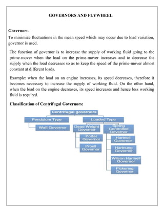
  • 1. GOVERNORS AND FLYWHEEL Governor:- To minimize fluctuations in the mean speed which may occur due to load variation, governor is used. The function of governor is to increase the supply of working fluid going to the prime-mover when the load on the prime-mover increases and to decrease the supply when the load decreases so as to keep the speed of the prime-mover almost constant at different loads. Example: when the load on an engine increases, its speed decreases, therefore it becomes necessary to increase the supply of working fluid. On the other hand, when the load on the engine decreases, its speed increases and hence less working fluid is required. Classification of Centrifugal Governors:
  • 2. Centrifugal Governor: In these governors, the change in centrifugal forces of the rotating masses due to change in the speed of the engine is utilized for movement of the governor sleeve. These governors are commonly used because of simplicity in operation. It consists of two balls of equal mass, which are attached to the arms. These balls are known as governor balls or fly balls. The balls revolve with a spindle, which is driven by the engine through bevel gears. The upper ends of the arms are pivoted to the spindle, so that the balls may rise up or fall down as they revolve about the vertical axis. The sleeve revolves with the spindle; but can slide up and down. The balls and the sleeve rise when the spindle speed increases, and falls when the speed decreases. In order to limit the travel of the sleeve in upward and downward directions, two stops S, S are provided on the spindle. The sleeve is connected by a bell crank lever to a throttle valve. The supply of the working fluid decreases when the sleeve rises and increases when it falls.
  • 3. When the load on the engine increases, the engine and the governor speed decreases. This results in the decrease of centrifugal force on the balls. Hence the balls move inwards and the sleeve moves downwards. The downward movement of the sleeve operates a throttle valve at the other end of the bell crank lever to increase the supply of working fluid an Thus the engine speed is increased. Hence, the extra power output is provided to balance the increased load. When the load on the engine decreases, the engine and the governor speed increases, which results in the increase of centrifugal force on the balls. Thus the balls move outwards and the sleeve rises upwards. This upward movement of the sleeve reduces the supply of the working fluid and hence the speed is decreased. Hence, the power output is reduced. Types of Centrifugal Governors: Depending on the construction these governors are of two types: (a)Gravity controlled centrifugal governors, (b)Spring controlled centrifugal governors. (a)Gravity Controlled Centrifugal Governors-In this type of governors there is gravity force due to weight on the sleeve or weight of sleeve itself which controls movement of the sleeve. These governors are comparatively larger in size. Spring Controlled Centrifugal Governors-In these governors, a helical spring or several springs are utilized to control the movement of sleeve or balls. These governors are comparatively smaller in size. There are three commonly used gravity controlled centrifugal governors (a) Watt governor (b)Porter governor (c) Proell governor
  • 4. Watt governor does not carry dead weight at the sleeve. Porter governor and Proell governor have heavy dead weight at the sleeve. In porter governor balls are placed at the junction of upper and lower arms. In case of Proell governor the balls are placed at the extension of lower arms. The sensitiveness of watt governor is poor at high speed and this limits its field of application. Porter governor is more sensitive than watt governor. The Proell governor is most sensitive out of these three. Watt Governor: This governor was used by James Watt in his steam engine. The spindle is driven by the output shaft of the prime mover. The balls are mounted at the junction of the two arms. The upper arms are connected to the spindle and lower arms are connected to the sleeve.
  • 5. We ignore mass of the sleeve, upper and lower arms for simplicity of analysis. We can ignore the friction also. The ball is subjected to the three forces which are centrifugal force (Fc), weight (mg) and tension by upper arm (T). Taking moment We ignore mass of the sleeve, upper and lower arms for simplicity of analysis. We can ignore the friction also. The ball is subjected to the three forces which are centrifugal force (Fc), weight (mg) and tension by upper arm (T). Taking moment about point O(intersection of arm and spindle axis), we get Porter Governor: A schematic diagram of the porter governor is shown in Figure 5.4(a). There are two sets of arms. The top arms OA and OB connect balls to the hinge O. The hinge may be on the spindle or slightly away. The lower arms support dead weight and connect balls also. All of them rotate with the spindle. We can consider one-half of governor for equilibrium. Let ii be the w'eiR3 t Of the ball.Ti and T, • be tension in upper and lower arms. respectively. N, be the centrifugal force. r be the radius of rotation of the ball from axis. and I is the instantaneous center of the louder arm. Taking moment of all for Yes acting on the ball about I and neglecting friction at the sleex‘e. u°e get
  • 6. DC x AD — ›s x ID ——/C=0 or or or (1+K)
  • 7. If friction at the sleeve is f, the force at the sleeve should be replaced by W+ for rising and by (W–f) for falling speed as friction opposes the motion of sleeve. Therefore, if the friction at the sleeve is to be considered, should be replaced by (W Spring controlled centrifugal governor: In these governors springs are used to counteract the centrifugal force. They can be designed to operate at high speeds. They are comparatively smaller in size. Their speed range can be changed by changing the initial setting of the spring. They can work with inclined axis of rotation also. These governors may be very suitable for IC engines, etc. The most commonly used spring controlled centrifugal governors are : a) Hartwell governor b)Wilson-Hartwell governor (b)Hartung governor Hartnell Governor: The Hartnell governor is shown in Figure 5.5. The two bell crank levers have been provided which can have rotating motion about fulcrums Oand O . One end of each bell crank lever carries a ball and a roller at the end of other arm. The rollers make contact with the sleeve. The frame is connected to the spindle. A helical spring is mounted around the spindle
  • 8. between frame and sleeve. With the rotation of the spindle, all these parts rotate. With the increase of speed, the radius of rotation of the balls increases and the rollers lift the sleeve against the spring force. With the decrease in speed, the sleeve moves downwards. The movement of the sleeve is transferred to the throttle of the engine through linkage. Characteristics of Governors: Different governors can be compared on the basis of following characteristics.  Stability: A governor is said to be stable when for every speed within the working range there is a definite configuration i.e. there is only one radius of rotation of the governor balls at which the governor is in equilibrium. For a stable governor, if the equilibrium speed increases, the radius of governor balls must also increase.  Sensitiveness of Governors: If a governor operates between the speed limits N1 and N2, then sensitiveness is defined as the ratio of the mean speed to the difference between the maximum and minimum speeds. Thus,N1 = Minimum equilibrium speed, N2 = Maximum equilibrium speed, and  Isochronous Governors: A governor is said to be isochronous when the equilibrium speed is constant (i.e. range of speed is zero) for all radii of rotation of the balls within the working range, neglecting friction. The isochronisms are the stage of infinite sensitivity. The isochronous governor is not of practical use because the sleeve will move to one of its extreme positions immediately the speed deviates from the isochronous speed.
  • 9.  Hunting : Hunting is the name given to a condition in which the speed of the engine controlled by the governor fluctuates continuously above and below the mean speed. It is caused by a governor which is too sensitive and which, therefore, changes by large amount the supply of fuel to the engine. Flywheel: A flywheel used in machines serves as a reservoir which stores energy during the period when the supply of energy is more than the requirement and releases it during the period when the requirement of energy is more than supply. For example, in I.C. engines, the energy is developed only during power stroke which is much more than the engine load, and no energy is being developed during suction, compression and exhaust strokes in case of four stroke engines and during compression in case of two stroke engines. The excess energy developed during power stroke is absorbed by the flywheel and releases it to the crankshaft during other strokes in which no energy is developed, thus Flywheel rotating the crankshaft at a uniform speed. when the flywheel absorbs energy, its speed increases and when it releases, the speed decreases. Hence a flywheel does not maintain a constant speed; it simply reduces the fluctuation of speed. In other words, a flywheel controls the speed variations caused by the fluctuation of the engine turning moment during each cycle of operation. It does not control the speed variations caused by the varying load. Coefficient of fluctuation of speed:
  • 10. Maximum Fluctuation of Energy: A turning moment diagram for a multi- cylinder engine is shown by a wavy curve in Fig. 22.4. The horizontal line AG represents the mean torque line. Let a1, a3, a5 be the areas above the mean torque line and a2, a4 and a6 be the areas below the mean torque line. These areas represent some quantity of energy which is either added or subtracted from the energy of the moving parts of the engine.
  • 11. Coefficient of fluctuation of energy: Difference between Flywheel and Governor
  • 12. Power Transmission Power transmission devices are very commonly used to transmit power from one shaft to another. Belts, chains and gears are used for this purpose. When the distance between the shafts is large, belts or ropes are used and for intermediate distance chains can be used. For belt drive distance can be maximum but this should not be more than ten metres for good results. Gear drive is used for short distances. 1. Belts and ropes are used when the distance between the axes of the two shafts to be connected is considerable. Such connectors are non-rigid and undergo strain while in motion. These devices are called non-positive drive because of the possibility of slip occurring between the belt and pulley. 2. Chain drive is used when the distance between the shaft centers is short and no slip is required. These connectors are referred to as a positive or non-slip drive. 3. Gears are used for transmitting motion and power when the distance between the driving& driven shafts is relatively small, and when a constant velocity ratio is desired. 4. Clutches are used for power transmission between co-axial shafts. Belts In case of belts, friction between the belt and pulley is used to transmit power. In practice, there is always some amount of slip between belt and pulleys, therefore, exact velocity ratio cannot be obtained. That is why, belt drive is not a positive drive. Therefore, the belt drive is used where exact velocity ratio is not required. The following types of belts shown in Figure 3.1 are most commonly used : The flat belt is rectangular in cross-section as shown in Figure 3.1(a). The pulley for this belt is slightly crowned to prevent slip of the belt to one side. It utilises the friction between the flat surface of the belt and pulley. The V-belt is trapezoidal in section as shown in Figure 3.1(b). It utilizes the force of friction between the inclined sides of the belt and pulley. They are preferred when distance is comparative shorter. Several V-belts can also be used together if power transmitted is more.
  • 13. The circular belt or rope is circular in section as shown in Figure 8.1(c). Several ropes also can be used together to transmit more power. The belt drives are of the following types : (a) open belt drive, and (b) cross belt drive. Open Belt Drive Open belt drive is used when sense of rotation of both the pulleys is same. It is desirable to keep the tight side of the belt on the lower side and slack side at the top to increase the angle of contact on the pulleys. This type of drive is shown in Figure 3.2. Cross Belt Drive In case of cross belt drive, the pulleys rotate in the opposite direction. The angle of contact of belt on both the pulleys is equal. This drive is shown in Figure 3.3. As shown in the figure, the belt has to bend in two different planes. As a result of this, belt wears very fast and therefore, this type of drive is not preferred for power transmission. This can be used for transmission of speed at low power.
  • 14.
  • 15. (i) Crossed belt system: the crossed belt system in which the driving and the drivenpulleys rotate in opposite directions. The belt leaves the bigger pulley at A and C and the smaller pulley at Band D. A line 02M is drawn parallel at AB will be perpendicular to O1A also.
  • 17. It may be noted from equations 1and 2 that: (I) The length of a crossed belt is more than that of an open belt, other conditions remainingthe same. (ii) The total length of a crossed belt is a function of (r1 + r2). If the sum of the radii of two pulleys be constant, the length of the cross belt required will be also remain constant. Ratio of tension Figure shows a flexible belt resting over the flat rim of a stationary pulley. The tensions T1and are such that the motion is impending Oust to take place) between the belt and the pulley. Considering the impending motion to be clockwise relative to the drum, the tension T1 is more than T2 is to be noted that only a part of the belt is in contact with the pulley. The angle subtended at the centre of the pulley by the position of belt in contact with it is called the angle of contact or the angle of lap Angle of contact θ = angle .AGB Let attention be focused on small element EF of the belt which subtends an angle δθ at the centre. The segment EF is acted upon by the following set of forces: • Tension T in the belt acting tangentially at S, • Tension ( T + 8T) in the belt acting tangentially at R • Normal reaction R exerted by the pulley rim, and • Friction force F = μR which acts against the tendency to slip and is perpendicular to normal reaction R.
  • 18.
  • 19. Power Transmitted by Belt Drive The power transmitted by the belt depends on the tension on the two sides and the belt speed. Let T1 be the tension on the tight side in ‗N‘ T2 be the tension on the slack side in ‗N‘, and V be the speed of the belt in m/sec. Then power transmitted by the belt is given by Tension due to Centrifugal Forces The belt has mass and as it rotates along with the pulley it is subjected to centrifugal forces. If we assume that no power is being transmitted and pulleys are rotating, the centrifugal force will tend to pull the belt as shown in Figure 3.14(b) and, thereby, a tension in the belt called centrifugal tension will be introduced.
  • 20.
  • 21. Let ‗TC‘ be the centrifugal tension due to centrifugal force. Let us consider a small element which subtends an angle at the centre of the pulley. Let ‗m‘ be the mass of the belt per unit length of the belt in ‗kg/m‘. Initial Tension When a belt is mounted on the pulley some amount of initial tension say ‗T0‘ is provided in the belt, otherwise power transmission is not possible because a loose belt cannot sustain difference in the tension and no power can be transmitted. When the drive is stationary the total tension on both sides will be ‗2 T0‘. When belt drive is transmitting power the total tension on both sides will be (T1 + T2), where T1 is tension on tight side, and T2 is tension on the slack side. If effect of centrifugal tension is neglected. Maximum Power Transmitted The power transmitted depends on the tension ‗T1‘, angle of lap , coefficient of friction ‗ ‘ and belt speed ‗V‘. For a given belt drive, the maximum tension (Tt), angle of lap and coefficient of friction shall remain constant provided that (a) the tension on tight side, i.e. maximum tension should be equal to the maximum permissible value for the belt, and (b) the belt should be on the point of slipping. Maximum Power Transmitted The power transmitted depends on the tension ‗T1‘, angle of lap , coefficient of friction ‗ ‘ and belt speed ‗V‘. For a given belt drive, the maximum tension (Tt), angle of lap and coefficient of friction shall remain constant provided that (c) the tension on tight side, i.e. maximum tension should be equal to the maximum permissible value for the belt, and
  • 22. (d) the belt should be on the point of slipping.
  • 23. Gear Drive A gear is a wheel provided with teeth which mesh with the teeth on another wheel, or on to a rack, so as to give a positive transmission of motion from one component to another. They are commonly used for power transmission or for changing power speed ratio in a power system but when they are not too far apart and when a constant velocity ratio is desired. Advantages and Disadvantages of Gear Drive The following are the advantages and disadvantages of the gear drive as compared to belt, rope and chain drives: Advantages 1. It transmits exact velocity ratio. 2. It may be used to transmit large power. 3. It has high efficiency. 4. It has reliable service. 5. It has compact layout. Disadvantages 1. The manufacture of gears require special tools and equipment. 2. The error in cutting teeth may cause vibrations and noise during operation Definitions There are several notation which are given below:
  • 24. 1.Pitch circle. It is an imaginary circle which by pure rolling action, would give thesame motion as the actual gear. 2.Pitch circle diameter. It is the diameter of the pitch circle. The size of the gear is usually specified by the pitch circle diameter. It is also known as pitch diameter. 3.Pitch point. It is a common point of contact between two pitch circles. 4.Pitch surface. It is the surface of the rolling discs which the meshing gears have replaced at the pitch circle. 5.Pressure angle or angle of obliquity. It is the angle between the common normal to two gear teeth at the point of contact and the common tangent at the pitch point. It is usually denoted by φ. The standard pressure angles are 14½ ° and 20° 6.Addendum. It is the radial distance of a tooth from the pitch circle to the top of the tooth. 7.Dedendum. It is the radial distance of a tooth from the pitch circle to the bottom of the tooth. 8.Addendum circle. It is the circle drawn through the top of the teeth and is concentric with the pitch circle. 9.Dedendum circle. It is the circle drawn through the bottom of the teeth. It is also calledroot circle. Note: Root circle diameter = Pitch circle diameter × cos φ, where φ is the pressure angle 10. Circular pitch. It is the distance measured on the circumference of the pitch circle froma point of one tooth to the corresponding point on the next tooth. It is usually denoted by pc. Mathematically, Circular pitch, Pc = Π D/T where D = Diameter of the pitch circle, and T = Number of teeth on the wheel. A little consideration will show that the two gears will mesh together correctly, if the two wheels have the same circular pitch. Note: If D1 and D2 are the diameters of the two meshing gears having the teeth T1 and T2 respectively, then for them to mesh correctly, PC = Π D1/T =Π D2/T
  • 25. 11. Diametral pitch. It is the ratio of number of teeth to the pitch circle diameter in millimetres. It is denoted by pd . Mathematically, Diametral pitch, Pd =T/D=Π/ PC where T = Number of teeth, and D = Pitch circle diameter. 12. Module. It is the ratio of the pitch circle diameter in millimeters to the number of teeth. Itis usually denoted by m. mathematically, Module, m = D /T Note : The recommended series of modules in Indian Standard are 1, 1.25, 1.5, 2, 2.5, 3, 4, 5, 6, 8, 10, 12, 16, and 20. The modules 1.125, 1.375, 1.75, 2.25, 2.75, 3.5, 4.5, 5.5, 7, 9, 11, 14 and 18 are of second choice. 13. Clearance. It is the radial distance from the top of the tooth to the bottom of the tooth, ina meshing gear. A circle passing through the top of the meshing gear is known as clearance circle. 14. total depth. It is the radial distance between the addendum and the dedendum circles ofa gear. It is equal to the sum of the addendum and dedendum. 15.Working depth. It is the radial distance from the addendum circle to the clearance circle.It is equal to the sum of the addendum of the two meshing gears. 16.Tooth thickness. It is the width of the tooth measured along the pitch circle. 17. Tooth space . It is the width of space between the two adjacent teeth measured alongthe pitch circle. 18.Backlash. It is the difference between the tooth space and the tooth thickness, as measured along the pitch circle. Theoretically, the backlash should
  • 26. be zero, but in actual practice some backlash must be allowed to prevent jamming of the teeth due to tooth errors and thermal expansion. 19.Face of tooth. It is the surface of the gear tooth above the pitch surface. 20.Flank of tooth. It is the surface of the gear tooth below the pitch surface. 21.Top land. It is the surface of the top of the tooth. 22.Face width. It is the width of the gear tooth measured parallel to its axis. 23.Profile. It is the curve formed by the face and flank of the tooth. 24.Fillet radius. It is the radius that connects the root circle to the profile of the tooth. 25.Path of contact. It is the path traced by the point of contact of two teeth from the beginning to the end of engagement. 26.Length of the path of contact. It is the length of the common normal cut-off by the addendum circles of the wheel and pinion. 27.Arc of contact. It is the path traced by a point on the pitch circle from the beginning to the end of engagement of a given pair of teeth. The arc of contact consists of two parts, i.e. (a) Arc of approach. It is the portion of the path of contact from the beginning of the engagement to the pitch point. (b) Arc of recess. It is the portion of the path of contact from the pitch point to the end of the engagement of a pair of teeth. Note : The ratio of the length of arc of contact to the circular pitch is known as contact ratio i.e. number of pairs of teeth in contact. Types of gear There are mainly five types of gear 1. Spur gear 2. Helical gear 3. Bevel gear 4. Worm gear 5. Rack & pinion gear
  • 27. Spur gear Spur gears or straight-cut gears are the simplest type of gear. They consist ofa cylinder or disk, and with the teeth projecting radially, and although they are not straight-sided in form, the edge of each tooth thus is straight and aligned parallel to the axis of rotation. These gears can be meshed together correctly only if they are fitted to parallel axles. The arrangement is known as spur gearing. Helical gear The teeth of helical gear are inclined to the axis In this type of gear. This ensures smooth action & more accurate maintenance of velocity ratio. The disadvantage is that the inclination of the teeth sets up a lateral thrust. A method of neutralizing this lateral or axial thrust is to use double helical gears (also known as herring bone gear) (a)Single helical gear (b) double helical gear
  • 28. Bevel gear The two non-parallel or intersecting, but coplanar shafts connected by gears are called bevel gears and the arrangement is known as bevel gearing. The bevel gears, like spur gears, may also have their teeth inclined to the face of the bevel, in which case they are known as helical bevel gears. The two non-intersecting and non-parallel i.e. non-coplanar shaft connected by gears are called skew bevel gears or spiral gears and the arrangement is known as skew bevel gearing or spiral gearing. This type of gearing also has a line contact, the rotation of which about the axes generates the two pitch surfaces known as hyperboloids. Worm gear They connect non-parallel, non-intersecting shafts which are usually at right angles. One of the gear is called „worm‟. It is essential part of a screw, meshing with the teeth on a gear wheel, called the ―worm wheel‖. The gear ratio is the ratio of number of teeth on the wheel to the number of thread on the worm. Its advantage is that it gives high gear ratio which are easily obtained & also smooth & quiet. Rack & pinion gear A rack is a spur gear of infinite diameter, thus it assumes the shape of a straight gear. The rack is generally used with a pinion to convert rotary motion into rectilinear motion
  • 29. Types of Gear Trains Two or more gears are made to mesh with each other to transmit power from one shaft to another. Such a combination is called gear train or train of toothed wheels. The nature of the train used depends upon the velocity ratio required and the relative position of the axes of shafts. A gear train may consist of spur, bevel or spiral gears. The different types of gear trains, depending upon the arrangement of wheels: 1. Simple gear train, 2. Compound gear train, 3. Reverted gear train, and 4. Epicyclic gear train. In the first three types of gear trains, the axes of the shafts over which the gears are mounted are fixed relative to each other. But in case of epicyclic gear trains, the axes of the shafts on which the gears are mounted may move relative to a fixed axis. Simple gear train When there is only one gear on each shaft, as shown in Figure, it is known as simple gear train. The gears are represented by their pitch circles. When the distance between the two shafts is small, the two gears 1 and 2 are made to mesh with each other to transmit motion fromone shaft to the other, as shown in Fig.(a).Since the gear 1 drives the gear 2, therefore gear 1 is called the driver and the gear 2 is called the driven or follower. It may be noted that the motion of the driven gear is opposite to the motion of driving gear.
  • 30. Let N1 = Speed of gear 1(or driver) in r.p.m., N2 = Speed of gear 2 (or driven or follower) in r.p.m., T1 = Number of teeth on gear 1, and T2 = Number of teeth on gear 2. Since the speed ratio (or velocity ratio) of gear train is the ratio of the speed of the driver to the speed of the driven or follower and ratio of speeds of any pair of gears in mesh is the inverseof their number of teeth, therefore Speed ratio = N1/N2=T2/T1 It may be noted that ratio of the speed of the driven or follower to the speed of the driver is known as train value of the gear train. Mathematically, Train value = N2/N1=T1/T2 From above, we see that the train value is the reciprocal of speed ratio. Sometimes, the distance between the two gears is large. The motion from one gear to another, in such a case, may be transmitted by either of the following two methods: 1. By providing the large sized gear, or 2. By providing one or more intermediate gears. A little consideration will show that the former method (i.e. providing large sized gears) is veryinconvenient and uneconomical method ; whereas the latter method (i.e. providing one or more intermediate gear) is very convenient and economical. It may be noted that when the number of intermediate gears are odd, the motion of both the gears (i.e. driver and driven or follower) is like as shown in Fig. (b). But if the number of intermediate gears are even, the motion of the driven or follower will be in the opposite direction ofthe driver as shown in Fig. (c). Now consider a simple train of gears with one intermediate gear as shown in Fig.(b). Let N1 = Speed of driver in r.p.m., N2 = Speed of intermediate gear in r.p.m., N3 = Speed of driven or follower in r.p.m., T1 = Number of teeth on driver, T2 = Number of teeth on intermediate gear, T3 = Number of teeth on driven or follower.
  • 31. Since the driving gear 1 is in mesh with the intermediate gear 2, therefore speed ratio for these two gears is N1/N2=T2/T1 ...(i)